HUNGARIAN JOURNAL OF INDUSTRY AND CHEMISTRY Vol. 48(1) pp. 67–70 (2020) hjic.mk.uni-pannon.hu DOI: 10.33927/hjic-2020-10
VIBRATION GENERATOR DEVICE BASED ON INDUSTRIAL VIBRATORS
PÉTERDECSI*1 ANDISTVÁNSZALAI1
1Institute of Mechatronics Engineering and Research, University of Pannonia, Gasparich Márk utca 18/A, Zalaegerszeg, 8900, HUNGARY
A low-cost vibration generator device based on industrial vibrators was designed. The control software was implemented in LabVIEW Environment. The device is able to generate an oscillating force of 8 kN and an amplitude of up to 4 mm at a frequency of 50 Hz to model low-amplitude, high-frequency vehicle vibrations. A National Instruments myRIO device was responsible for data acquisition, with which a signal of a piezoelectric accelerometer was detected. The test results show that the device is able to generate a sinusoidal harmonic acceleration.
Keywords: industrial vibrator, vibration generator, test equipment
1. Introduction
The suspension of a car acts as a connector between the chassis and the road. It provides a comfortable ride for passengers while maintaining maneuverability. Nowa- days, comfort is a prerequisite so car manufacturers have started developing new technologies for isolating vibra- tions [1,2]. The vibration can be dampened or converted into electrical energy [3]. Electro- [4] and magnetorhe- ological dampers [5,6] are filled with a special fluid.
Small ferromagnetic particles are dispersed in a carrier fluid, usually silicone oil. The diameters of the particles fall within the micro- and nanometre ranges. When sub- jected to an electric or magnetic field, the particles form chains. These chains provide an elevated level of resis- tance against shear stress, therefore, the apparent viscos- ity of the fluid rises [7,8].
Using adjustable shock absorbers, the natural fre- quency of the suspension can be altered. The damping coefficient can be varied depending on the road condi- tions or the driver’s preference. The reaction time of these fluids is very short (approximately10 ms), so the technol- ogy can be used in systems where short reaction times are required [9].
Suspension-testing equipment is crucial during the development phase. The acquisition cost of appliances for this task is very high. Our goal was to develop a low-cost piece of equipment for testing shock absorbers that is ca- pable of generating high frequencies (within an accept- able range for vehicles) and vibrations of low amplitude.
*Correspondence:decsi.peter@mk.uni-pannon.hu
𝑥1
𝑥2
𝑚1
𝑚2
𝑘1 𝑏1
𝑘2 𝑏2
𝑥𝑟
(a)structure model
𝑚2 𝑚1 𝑘1
𝑘2 𝑏1
𝑏2 𝑥 1
𝑥 2
𝑥 𝑟 𝑥 𝑟
(b)structure graph Figure 1:Quarter-car model
2. Modeling the vehicle
Several options of modeling the suspension of vehicles are available; quarter-, half- and full-car models can be used to describe the system, which is chosen depends on the aim of the study. The quarter-car model was chosen for this study due to its simplicity. Industrial vibrators are able to generate vibrations of constant amplitude. To change the generated force and amplitude, it is necessary to stop the device and mechanically set the eccentricity, therefore, the roll, pitch and yaw of the vehicle is hard to model with such a device.Fig. 1shows a quarter-car model. The system has two degrees of freedom (DOF), m1 denotes the mass of the chassis, m2 represents the mass of the wheel, which is usually referred to as the un- sprung mass. The related displacements are labelled asx1
68 DECSI ANDSZALAI
andx2, spring stiffnesses askand viscous damping coef- ficients asb. The wheel and chassis are connected through a springk1and a damperb1. The wheel and the road are connected through a spring and damper (elastic tire with damping loss)k2,b2. Based on the structure graph, the equilibrium equations can be written in the form:
m1x¨1=−b1( ˙x1−x˙2)−k1(x1−x2) m2x¨2=b1( ˙x1−x˙2) +k1(x1−x2)+
+b2( ˙xr−x˙2) +k2(xr−x2).
(1)
Based onFig. 1andEq. 1, it is clear that the system has a cross-variable source, namely speed.
3. Modeling the proposed system
This research presents an equivalent model based on industrial vibrators. Industrial vibrators are traditional asynchronous motors with a dual shaft on which eccen- tric masses are mounted.
fc=mrω2 (2) wheremdenotes the eccentric mass,rrepresents the ec- centricity, which is the distance between the axis center point and the center of gravity of the eccentric mass, and ωstands for the rotational speed. Due to the eccentricity, a centrifugal force is generated because of the rotation (Eq. 2). If two motors of opposite rotational directions are mounted together, lateral forces cancel each other out, therefore, a one-axis oscillation is created. A system with two degrees of freedom was designed using industrial vi- brators. The model of the system is depicted in Fig. 2:
The differential equations of this system are:
m1x¨1 + k1(x1−x2) + + b1( ˙x1−x˙2) +fin= 0 m2x¨2 − k1(x1−x2)−
− b1( ˙x1−x˙2) +k2x2+ ˙x2b2= 0 (3)
X1
Xr
= s2b1b2+s(k2b1+b2k1) +k1k2
s4m1m2+s3(m1(b1+b2) +m2b1) +s2(m1(k1+k2) +m2k1+b1b2) +s(k1b2+k2b1) +k1k2
(4)
X1
F = s2m2+s(b1+b2) +k1+k2
s4m1m2+s3(m1(b1+b2) +m2b1) +s2(m1(k1+k2) +m2k1+b1b2) +s(k1b2+k2b1) +k1k2
(5)
According to the impedance network of the quarter- car model shown inFig. 3, the transfer function can be written in the formEq. 4. The impedance network of the proposed system is shown inFig. 4and contains the trans- fer function ofEq. 5:
It can be seen that the transfer functionX1/Xrof the quarter-car model (Eq. 4) is similar to that of the transfer
𝑓𝑐
Ω 𝑥1
𝑥2
𝑚1
𝑘1 𝑏1
𝑘2 𝑏2
(a)structure model
𝑥 1
𝑥 2 𝑘1
𝑘2 𝑏1
𝑏2 𝑚1
𝑚2
𝑓𝑖𝑛
(b)structure graph Figure 2:Vibrator model
𝑠 𝑘2
𝑠 𝑘1
1 𝑏1
1 𝑠𝑚1 1
𝑏2
𝑣𝑟 1
𝑠𝑚2
𝑥 1 𝑥 2
Figure 3:Impedance network of the quarter-car model
𝑠 𝑘2
1 𝑏2
1 𝑠𝑚2
𝑠 𝑘1
1 𝑏1
1 𝑠𝑚1 𝑓𝑖𝑛
𝑥 1 𝑥 2
Figure 4:Impedance network of the vibrator model
Hungarian Journal of Industry and Chemistry
VIBRATION GENERATOR DEVICE BASED ON INDUSTRIAL VIBRATORS 69
functionX1/Fof the proposed system (Eq. 5). The char- acteristic polynomials, i.e. the denominators, are identical as the two systems differ only in terms of the excitation source. The numerators are of the same degree, therefore, the characteristics of the system response are similar, that is to say the dynamics of the two systems are not sig- nificantly different. The breakpoints in terms of the fre- quency response are expected to be shifted.
4. Implementation
After deriving the differential equations, a Simulink model was created to choose the optimal combinations of parameters (mass, spring stiffness and damping coeffi- cients). According to the simulations, the connection be- tween the chassis and the ground should be as stiff as pos- sible in order to focus the force on the shock absorbers.
It should not be too rigid, otherwise the force acting on the ground would be excessive and affect the building too significantly. The moving mass, where the motors are mounted, should be small to achieve the maximum pos- sible exciting force, therefore, more force can be used to accelerate the payload.
During the design process, models with two or three degrees of freedom were examined. The motion became chaotic with three independent masses, that is 3 DOFs, so the spring stiffness available was insufficient to produce a stable and predictable shape of sinusoidal motion. It was concluded that a system with 2 DOFs generates a sta- ble sinusoidal oscillation with multiple frequency com- ponents in terms of the shape of motion.
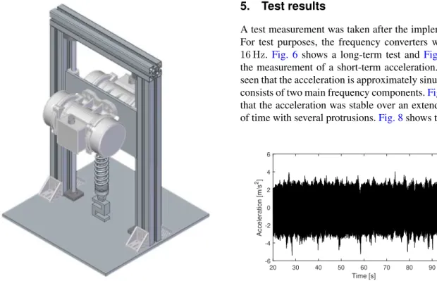
The device, shown inFig. 5, consists of two three- phase asynchronous two-pole industrial vibrators each
Figure 5:The implemented vibration generator
with a nominal performance of300 W. The centrifugal force can be incrementally set up to4070 Nat a frequency of 50 Hz on one motor. The motors are operated with frequency converters, thus the frequency can be set. If the motors operate in opposite rotational directions and a suitable arrangement is applied, the lateral forces can- cel each other out, thereby creating a one-axis oscillation.
The frequency converters are controlled with analogue signals generated by a National Instruments myRIO de- vice.
A piezoelectric accelerometer was mounted on the sheet holding the vibrating motors. A high-pass filter with a cutoff frequency of1 Hzwas installed to cancel out the bias voltage of the accelerometer. Data was acquired by the Field-Programmable Gate Array (FPGA) module of the myRIO device on analogue channels. The AC sig- nal was coupled to a high-pass filter with a cutoff fre- quency of1 Hz. The sensitivity of the accelerometer was 100 mV/g and the analogue input of the myRIO device was±10 V. An instrumentation amplifier with an ampli- fication of 7.08 was built to utilize the full range of the A/D converter. The FPGA module takes a sample accord- ing to the previously set sampling frequency, which can be set up to100 kHz. The data is stored temporarily in the First In First Out (FIFO) memory on the myRIO device.
A second Virtual Instrument (VI), which displays and stores the data in Technical Data Management Stream- ing (.TDMS) file format, was run on the controlling PC.
The VI read out data from the FIFO memory in batches.
These batches were stored in the TDMS file, creating a reliable data acquisition. Meanwhile, following the appli- cation of a Fast Fourier Transform algorithm, a frequency spectrum was displayed on the controlling PC.
5. Test results
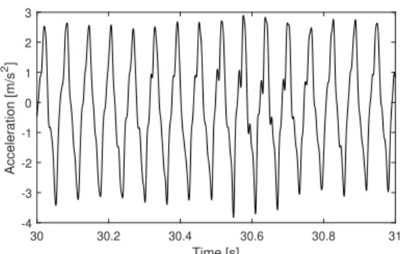
A test measurement was taken after the implementation.
For test purposes, the frequency converters were set at 16 Hz. Fig. 6shows a long-term test and Fig. 7shows the measurement of a short-term acceleration. It can be seen that the acceleration is approximately sinusoidal and consists of two main frequency components.Fig. 6shows that the acceleration was stable over an extended period of time with several protrusions.Fig. 8shows that the set
20 30 40 50 60 70 80 90 100
Time [s]
-6 -4 -2 0 2 4 6
Acceleration [m/s2]
Figure 6:Test measurement, long duration
48(1) pp. 67–70 (2020)
70 DECSI ANDSZALAI
30 30.2 30.4 30.6 30.8 31
Time [s]
-4 -3 -2 -1 0 1 2 3
Acceleration [m/s2]
Figure 7:Test measurement, short duration
0 10 20 30 40 50 60 70 80 90 100
Frequency (Hz) -40
-30 -20 -10 0 10
Power Spectrum (dB)
Figure 8:Frequency spectrum of the test measurement
frequency was present in the spectrum alongside multiple frequency components.
6. Conclusion
According to our experience and the aforementioned re- sults, it can be concluded that a cost-effective vibration generator was designed and produced. The device is able to generate an amplitude of vibration equal to4 mmwith a frequency of up to50 Hz. The total centrifugal force was as high as8 kN, of which7500 Ncould be focused on the examined sample. The frequency can be set be- tween1 Hzand50 Hz, however, as shown inEq. 2, the centrifugal force depends on the rotational speed.
The amplitude cannot be set, and when the natural fre- quency of the system, namely1.3 Hz, is exceeded, the amplitude becomes constant. At this frequency, the cen- trifugal force is low so resonance can be avoided. The excitation force can be set between 0 and 100% by modi- fying the eccentricity of the motors. To set the eccentric- ity, the motors must be powered down and the side covers removed.
The vibration generators that are typically used (elec- trodynamic and hydraulic) are able to create higher am- plitudes and higher vibrational frequencies, but these de- vices belong to a different cost category.
Acknowledgement
The project has been supported by the European Union, co-financed by the European Social Fund. EFOP-3.6.2- 16-2017-00002
REFERENCES
[1] Qin, Y.; Tang, X.; Jia, T.; Duan, Z.; Zhang, J.; Li, Y.; Zheng, L.: Noise and vibration suppression in hybrid electric vehicles: State of the art and chal- lenges,Renew. Sustain. Energy Rev., 2020,124,DOI:
10.1016/j.rser.2020.109782
[2] Ning, D.; Sun, S.; Du, H.; Li, W.; Li, W.: Control of a multiple-DOF vehicle seat suspension with roll and vertical vibration,J. Sound Vib., 2018,435, 170–191,
DOI: 10.1016/j.jsv.2018.08.005
[3] Zhang, Z.; Xiang, H.; Shi, Z.; Zhan, J.: Exper- imental investigation on piezoelectric energy har- vesting from vehicle-bridge coupling vibration,En- ergy Convers. Manag., 2018, 163, 169–179, DOI:
10.1016/j.enconman.2018.02.054
[4] Holzmann, K.; Kemmetmüller, W.; Kugi, A.; Stork, M.: Design, mathematical modeling and control of an assymetrical electrorheological damper,IFAC Proceedings Volumes, 2006, 39(16), 372–377, DOI:
10.3182/20060912-3-DE-2911.00066
[5] Graczykowski, C.; Pawłowski, P.: Exact phys- ical model of magnetorheological damper, Appl. Math. Model., 2017, 47, 400–424, DOI:
10.1016/j.apm.2017.02.035
[6] Yao, G.Z.; Yap, F.F.; Chen, G.; Li, W.H.; Yeo, S.H.: MR damper and its application for semi- active control of vehicle suspension system,Mecha- tronics, 2002, 12(7), 963–973, DOI: 10.1016/S0957- 4158(01)00032-0
[7] Carlson, J.D.: What Makes a Good MR Fluid?, J.
Intel. Mat. Syst. Str., 2002, 13(7-8), 431–435, DOI:
10.1106/104538902028221
[8] Rankin, P.J.; Ginder, J.M.; Klingenberg, D.J.:
Electro- and magneto-rheology, Curr. Opin. Col- loid Interface Sci., 1998, 3(4), 373–381, DOI:
10.1016/S1359-0294(98)80052-6
[9] Olabi, A.; Grunwald, A.: Design and application of magneto-rheological fluid, Mater. Des., 2007, 28(10), 2658–2664,DOI: 10.1016/j.matdes.2006.10.009
Hungarian Journal of Industry and Chemistry