A Compliance Model to Improve the Accuracy of the da Vinci Research Kit (dVRK)
Grace Chrysilla
1,2, Nickolas Eusman
1,2, Anton Deguet
1, and Peter Kazanzides
11Department of Computer Science, Johns Hopkins University, Baltimore, MD USA, pkaz@jhu.edu
2These authors contributed equally to the work during internships at JHU
Abstract: The da Vinci surgical robot is widely used for minimally-invasive surgery. It inserts multiple articulated instruments through small incisions into the patient. The robot system contains encoders to measure joint displacements which, when combined with the kinematic model of the robot, measures the instrument position and orientation. But, the accuracy of these measurements is affected by non-kinematic errors, such as bending of the instruments due to applied loads. We develop a compliance model that relates displacement of the first two joints of the da Vinci Patient Side Manipulator (PSM) to lateral forces applied to the instrument shaft. This model enables us to compensate for these errors based on the measured joint efforts, which are derived from the measured motor currents. We perform experiments with the open-source da Vinci Research Kit (dVRK) to estimate the model parameters and to evaluate the accuracy improvement that results from application of this model. Preliminary results indicate that the model-based correction can reduce instrument position error due to externally-applied forces.
Keywords: da Vinci Research Kit (dVRK); compliance model; calibration
1 Introduction
The da VinciR surgical robot [1], Fig. 1, is widely used for minimally invasive surgery. It currently relies on teleoperation by the surgeon, who sits at a master console that provides stereo video from inside the patient via a stereo endoscope inserted through one incision (port). The console also contains two Master Tool Manipulators (MTMs), which the surgeon uses to provide motion commands to the Patient Side Manipulators (PSMs) that drive robotic surgical instruments inside the patient. In the conventional scenario, a human surgeon is inside the control loop and uses his or her visual feedback to correct for positioning errors. In general, positioning errors can be due to kinematic errors, such as imprecise knowledge of the robot’s kinematic parameters, and non-kinematic errors, such as friction, backlash and deformation of the robot’s mechanical structure due to gravity or other externally-applied forces. This is especially true for the da Vinci instruments, which are cable-driven and have thin diameters (typically 5 mm or 8 mm).
While positioning accuracy is not crucial for conventional teleoperation, it can be
Figure 1
da Vinci Surgical Robot: patient side robot on left; master console on right.
important in other situations, such as when making measurements or when enforcing virtual fixtures. In these cases, it can be beneficial to compensate for the positioning errors. One solution is to track the surgical instrument in the endoscopic video, since direct visual observation of the tool tip is not affected by kinematic or non-kinematic errors. However, optical tracking of da Vinci instruments remains a challenging research problem (especially when optical markers are not used) and is the subject of many other efforts [2].
We therefore focus on an approach that does not require tracking of the instrument.
Further, we consider only non-kinematic errors due to deformation of the instrument, which can only improve the positioning accuracy for applications that require contact with the environment. Nevertheless, there are several existing applications that could benefit from such a capability. For example, researchers at the University of British Columbia (UBC) used a da Vinci instrument to push against the prostate in order to register the da Vinci robot coordinate frame to a transrectal ultrasound (TRUS) coordinate frame [3]. In this case, deformation of the instrument will contribute to the overall registration error. Another potential scenario is 3D reconstruction of 2D ultrasound images when the 2D ultrasound probe is swept along an organ surface by a da Vinci instrument [4]. Because accuracy is important for these types of applications, the group at UBC also attached an optical marker frame to the da Vinci instrument and tracked it with the endoscope camera [5]. Improving the positioning accuracy of the da Vinci could eliminate the need for this additional tracking. Virtual fixtures provide another application scenario that could benefit from improved accuracy;
for example, in cases where a guidance virtual fixture is defined by probing the anatomy [6] (there are other applications of virtual fixtures in the literature, but many do not involve contact with the environment). In another application, the da Vinci instrument was used to palpate tissue to estimate its stiffness [7], but this actually measured the stiffness of both the instrument and the tissue. In many cases, the
instrument will be much stiffer than the tissue and therefore introduce negligible error, but at some instrument orientations the error contribution may be larger.
The above application examples motivate the approach presented in this paper, which is to develop a simplified compliance model of the da Vinci PSM and surgical instrument and to use this model to reduce the error in estimation of the instrument tip position based on the encoder measurements and kinematic parameters. The research is performed with the open-source da Vinci Research Kit (dVRK) [8], which enables full access to all feedback data from the da Vinci system. In particular, this method utilizes the measured encoder feedback and the estimated joint torques, which are calculated from the measured motor currents. The dVRK also provides access to the robot controller, thereby allowing the compliance-based correction to be incorporated in the system. The contribution of this work is the identification of a model that is simple to implement, but can nevertheless improve the position accuracy of da Vinci instruments.
2 Compliance Model
The position and orientation of the da Vinci instrument is computed based on applying the forward kinematics to the measured joint positions,q, which are obtained from incremental encoders mounted on the actuators (motors). In general, it is necessary to distinguish between joints and actuators on the da Vinci due to coupling, especially between the four actuators that drive the instrument wrist and gripper. Our analysis, however, focuses on the first two joints of the da Vinci PSM, which are not coupled, so we do not make this distinction in the following.
The PSM contains a remote center of motion (RCM) that is designed to be located at the insertion point (port) on the patient’s body. The first two joints are rotations about the RCM and the third joint is a linear translation through the RCM, as illustrated in Fig. 2-left. We consider the effect of external forces applied to the instrument, which can affect the instrument position as follows: (1) increase the difference between the commanded joint position and the measured joint position, and (2) displace the instrument due to deformation of the mechanical structure. The first effect is dependent on the control performance of the da Vinci and only affects the accuracy with which the da Vinci can be controlled. Because the encoders measure the displacement, applying the forward kinematics to the measured encoder positions will yield an instrument position that takes into account this displacement. The second effect (deformation due to mechanical compliance, Fig. 2-middle) is not measured by the encoders, however, and therefore decreases the position accuracy.
Thus, our focus is to develop a model for this compliance and to use this model to predict and correct for the mechanical deformation. Although all links of the da Vinci are subject to compliance, we focus on lateral forces acting on the instrument shaft because compliance of the shaft in the two lateral directions is significantly higher than in the axial direction (Z3in Fig. 2-left). Furthermore, we ignore compliance of the instrument wrist because we expect it to be a less significant contributor to positioning inaccuracy. Figure 2-right also shows backlash between the instrument shaft and the cannula (in the figure, the cannula is exaggerated in size to better illustrate the backlash phenomenon).
Z1
Z2 Z3
RCM Compliance Backlash
Figure 2
Left: PSM Kinematics, showing axes of first three joints, where joints 1 and 2 rotate about a common remote center of motion (RCM), and joint 3 translates through this RCM.Center: Illustration of instrument compliance.Right: Illustration of backlash. Note that backlash between instrument shaft
and cannula is exaggerated for visual effect.
Due to the kinematic design of the da Vinci PSM, lateral forces applied to the instrument shaft align with the first two rotary joints, so we are able to develop a compliance model considering only these two joints. For analysis, we decompose the lateral force into two orthogonal forces, where one force applies a torque around the first joint and the other force applies a torque around the second joint. For each rotary jointq, we consider the following compliance model:
∆qde f=δsgn(τext) +K(L)τext (1) Here,τext is the external applied torque,∆qde f is the angular displacement, andδ is a small angular displacement due to backlash.K(L)is an angular correction factor, relating angular displacement to applied torque, that is assumed to vary based on the length,L, from the RCM to the point at which the force is applied. These parameters are summarized in Table 1.
Equation (1) can be used to correct the measured joint angle by subtracting∆qde f, given an estimate of the external joint torqueτext and knowledge of the parameters δ andK(L). Fortunately, the dVRK software provides the measured joint torque, τmeas, which is the sum of the external joint torque, τext, and the internal torque, τint. In general, it is challenging to estimate the internal torque using model-based methods, such as Lagrangian dynamics, due to nonlinear effects such as friction and cable compliance. Nevertheless, some groups have achieved reasonable results
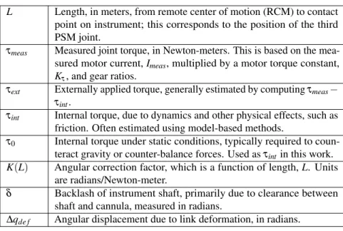
Table 1 Nomenclature
L Length, in meters, from remote center of motion (RCM) to contact point on instrument; this corresponds to the position of the third PSM joint.
τmeas Measured joint torque, in Newton-meters. This is based on the mea- sured motor current,Imeas, multiplied by a motor torque constant, Kτ, and gear ratios.
τext Externally applied torque, generally estimated by computingτmeas− τint.
τint Internal torque, due to dynamics and other physical effects, such as friction. Often estimated using model-based methods.
τ0 Internal torque under static conditions, typically required to coun- teract gravity or counter-balance forces. Used asτint in this work.
K(L) Angular correction factor, which is a function of length,L. Units are radians/Newton-meter.
δ Backlash of instrument shaft, primarily due to clearance between shaft and cannula, measured in radians.
∆qde f Angular displacement due to link deformation, in radians.
using this approach for the dVRK [9, 10]. Alternatively, a neural network could learn the dynamics, as recently demonstrated for a different robotic surgical instrument wrist [11].
In this paper, we simplify the problem by considering the quasi-static case, where measurements are taken with the robot in a fixed position. In this case,τint can be represented by a bias (offset) torque,τ0(q), which can be calibrated in advance by rotating the joint through a range of angles. Conceptually, this is similar to considering only the gravity term of the dynamics equation, though in the case of the da Vinci PSM the bias torque is primarily due to the mechanical counterbalance. In the future, one of the dynamics-based methods cited above can be incorporated with the developed compliance model. To summarize, for the first two rotary joints, the corrected joint position ˆqcan be computed from the measured joint positionqand estimated external torqueτext (here,τmeas−τ0), greater than a defined thresholdτmin, as follows:
ˆ q=
( q−δsgn(τext)−K(L)τext if|τext|>τmin
q otherwise
(2)
In our testing, we empirically setτminto 0.1 N-m for joint 1 and 0.2 N-m for joint 2. The nonzero values forτmincause a discontinuity in ˆq, which must be further investigated if used for feedback control in the future. It is possible to setτminto 0, but in that case the joint correction value would likely oscillate betweenδand−δ due to measurement noise.
3 Experiments
We performed experiments to gather data for developing the model and then to test the application of this model to compensate for the inaccuracy due to link deformation.
We first measured the torque offset,τ0, by moving the first and second joints through their range of motion in 5 degree increments, while recording the measured effort.
Because the position control (PID controller) was active, the measured effort with no external load corresponds to the torque offset.
We evaluated different data collection methods for estimating the instrument backlash and compliance, including use of an optical tracking system or a dial indicator to measure deflection and a force sensor or precision weights to apply the external forces/torques. Ultimately, however, we settled on a simple approach that does not require any external measurement devices. Specifically, we clamped the da Vinci instrument against a rigid beam, as shown in Fig. 3. We then performed small incremental rotations of joints 1 and 2, while recording the measured joint torque.
We assume that the beam is rigid and therefore that the actual instrument tip position does not change as the instrument applies increasing forces against the clamp. The advantage of clamping the instrument, rather than moving into the beam in one direction, is that it enables estimation of both the instrument compliance and the backlash.
We developed a Python program that communicates with the PSM via a ROS [12]
clamp
clamp RCM
RCM Joint 2
Joint 1
Figure 3
Data collection setup: PSM instrument is clamped against rigid beam while collecting measured joint position and torque (effort).
interface. Based on the setup in Fig. 3, the PSM’s instrument was aligned with the aluminum beam and the linear joint was moved to locate the distal part of the instrument shaft at a distance of 0.09 meters (insertion depth) from the RCM point.
The instrument was then clamped against the beam.
The robot was instructed to move in one direction in increments of 0.25 mm, until the absolute value of the measured effort exceeded 1.0 N-m. Then, it reversed direction and moved in 0.25 mm increments until the absolute value of the measured effort exceeded 1.0 N-m. Finally, it reversed direction again and moved back in increments of 0.25 mm until it crossed the start point. At each position, the software recorded an average of 20 measurements of the position and effort of the joint under test. This procedure was repeated at a total of 14 insertion depths, ranging from 0.09 m to 0.22 m. The above data collection was performed for the two orthogonal directions corresponding to the rotations of the first two PSM joints. The data was analyzed to estimate the angular correction factor for each orthogonal direction.
Finally, the compliance model was tested by pushing against a divot in an aluminum plate, while recording the measured joint positions and efforts. The correction model, Equation (2), was applied to the measured positions of joints 1 and 2 to obtain the corresponding corrected joint positions.
4 Results
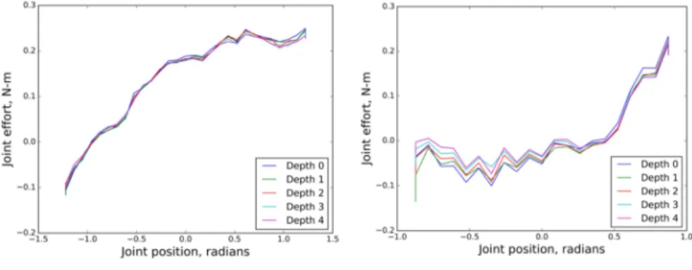
Figure 4 shows the measured torque as a function of joint angle for joints 1 and 2. The data shows that the torque offset varies as a function of the joint angle (as expected), but does not vary significantly as a function of insertion depth.
Figure 5 plots the measured joint effort as a function of joint position, for one experiment in which the joint was moved while the instrument shaft was clamped to the rigid beam. Hysteresis is evident in both directions (i.e., corresponding to direction of motion for joints 1 and 2). This hysteresis is primarily due to backlash between the instrument shaft and cannula and therefore the distance between the best-fit lines provides a measurement of the backlash in each direction.
Joint 1 effort (torque offset) as a
function of joint angle Joint 2 effort (torque offset) as a
function of joint angle
Figure 4
Measurements of torque offset as a function of joint angle for joint 1 (left) and joint 2 (right) at different instrument insertion depths.
Figure 5
Measurements of joint effort as a function of joint position when instrument tip is clamped against beam for joint 1 (left) and joint 2 (right). Hysteresis (due to backlash) is evident. Plots include best-fit lines
for each direction of motion.
We determine the angular correction factorsK1(L)andK2(L)for joints 1 and 2, respectively, by computing the slopes of the lines in Fig. 5, for each instrument depth.
The results are shown in Fig. 6, along with the best-fit cubic polynomials. These polynomials define the inverse ofK1(L)andK2(L):
K1(L) = 1
639.16L3−432.35L2+136.32L+3.12 (3)
K2(L) = 1
3163.17L3−1969.15L2+448.92L−6.00 (4) Figure 6 also reveals that this parameter is not symmetric, particularly for joint 2. Since the instrument shaft is symmetric, this is most likely due to the overall mechanical structure which, for joint 2, includes a double four-bar linkage.
0.08 0.10 0.12 0.14 0.16 0.18 0.20 0.22
Distance from RCM, m
12 13 14 15 16 17 18 19
Slope, N-m/radian
Joint 1
all data rightward data leftward data
0.08 0.10 0.12 0.14 0.16 0.18 0.20 0.22
Distance from RCM, m
20 22 24 26 28 30 32
Slope, N-m/radian
Joint 2
all data outward data inward data
Figure 6
Inverse of angular correction factors as a function of insertion depth for directions corresponding to motion of joint 1 (left) and joint 2 (right).
0.02 0.00 0.02 0.04 0.06 0.08
Joint Effort, N-m
0.03 0.02 0.01 0.00 0.01 0.02 0.03 0.04 0.05 0.06
Joint Displacement, radians
uncorrected position corrected position
0.16 0.14 0.12 0.10 0.08
Joint Effort, N-m
0.16 0.14 0.12 0.10 0.08 0.06 0.04
Joint Displacement, radians
uncorrected position corrected position
Figure 7
Uncorrected position of joint 1 compared to corrected position computed from model, while robot is pushing against divot in aluminum plate. Joint 1 is pushing in positive direction (left) or negative
direction (right); in either case, true joint position should remain constant.
2.0 1.5 1.0 0.5 0.0 0.5
Joint Effort, N-m
0.58 0.57 0.56 0.55 0.54 0.53 0.52 0.51 0.50
Joint Displacement, radians
uncorrected position corrected position
Figure 8
Uncorrected position of joint 2 compared to corrected position computed from model, while robot is pushing against divot in aluminum plate. Joint 2 is pushing in positive direction (left) or negative
direction (right); in either case, true joint position should remain constant.
Finally, Figs. 7 and 8 compare the corrected and uncorrected positions of joints 1 and 2 while the robot is pushing against a divot in the aluminum plate. The plots show that the uncorrected joint positions are changing, even though the tip is not moving, due to the instrument compliance. In contrast, the corrected joint positions are nearly constant, which indicates an improvement in the accuracy of the robot.
5 Discussion
The da Vinci instrument position correction based on the compliance model shows promising results for increasing the accuracy of the da Vinci robot, especially when external forces are applied to the instrument. These results were obtained by focusing on one of the larger sources of error – the backlash and deformation of the instrument shaft in the lateral directions. These errors align with the first two robot joints and therefore we develop a correction model in joint space, using the measured joint torque (effort). Because the dVRK power amplifiers implement torque control, it is likely that the method would work equally well using the commanded joint torque instead of the measured joint torque.
The compliance model includes several experimentally determined parameters, in- cluding the angular correction factorK(L), backlashδ, and joint torque offsetτ0(q).
The angular correction factorK(L)was determined by first fitting a line to the mea- sured displacement and torque for each value ofL. A cubic polynomial inLwas then fit to the slopes of these lines, which provided the inverse of the angular correction factor for each joint. Future work should develop a mathematical model that is based on mechanical principles.
The experiments used the joint torque offset,τ0(q), in lieu of the internal torque, which typically would include the effects of robot dynamics and other mechanical effects, such as friction. This simplification is valid for the static (or near static) case, where the commanded torque is primarily required to compensate for gravity or counter-balance forces. This is not an unrealistic simplification, since the da Vinci instruments are generally moved slowly and deliberately during surgical procedures.
Also, in many cases, such as the da Vinci to TRUS registration previously cited [3], an accurate position measurement is only required when the instrument is not moving.
Nevertheless, the implementation could be improved by incorporating estimates of the internal torque based on the dVRK dynamics [9, 10] or other methods [11].
Our results also are affected by small approximations in our methods. For example, we defined the instrument length,L, based on the measured joint position of the third axis (translation). This provides the length from the RCM point to a defined point on the instrument, which is a little offset with respect to the instrument tip (where forces would likely be applied in actual use) or with respect to the distal end of the instrument shaft (which is where we applied forces during our data collection). Thus, there will be a small discrepancy between the assumed length and the actual moment arm, which will have a minor effect on the accuracy of compensation.
Finally, our experimental results showed the ability to improve the accuracy at a single point (e.g., while pushing against a divot). We have not yet demonstrated accuracy improvement over the PSM workspace because, at present, inaccuracy of the dVRK kinematics contributes a larger source of error.
6 Conclusions
We developed a simple compliance model that relates lateral deflection of the da Vinci instrument shaft to angular offsets in the first two joints of the Patient Side Ma- nipulator (PSM). Model parameters can be estimated using a simple data collection setup (a rigid beam) that does not require external measurement devices. Once the model parameters are obtained, real-time correction of instrument tip position can be achieved by applying the compliance model to the measured torques from the first two joints. While we expect some variation of model parameters between instru- ments, our hypothesis is that most instruments (with the same diameter) will have similar compliance models. We further expect that results will be similar between da Vinci systems, though there is likely to be some variability in the estimation of the internal torques,τint, or the backlash,δ.
The experiments were performed under static conditions to simplify the estimation of the internal torque, but we are investigating existing methods to estimate the internal
torque under dynamic conditions. In addition, accuracy of the PSM can be improved by calibration of the kinematic parameters.
The contribution of this work is not in the compliance model, which is straightforward, but rather in the demonstration that such a simple model can provide significant accuracy improvements. We are currently working to incorporate the data collection, parameter estimation, and real-time compensation methods into the open-source da Vinci research kit software. This will enable other researchers to replicate this work (currently, there are more than 35 dVRK systems around the world), with the added benefit of providing data to determine how the model parameters vary between different da Vinci systems and instruments.
Acknowledgment
This work was supported by National Science Foundation (NSF) National Robotics Initiative (NRI) grant 1637789 and by JHU internal funds.
References
[1] G. Guthart and J. Salisbury. The IntuitiveT Mtelesurgery system: Overview and application. InProc. IEEE Intl. Conf. on Robotics and Automation (ICRA), pages 618–621, May 2000.
[2] D. Bouget, M. Allan, D. Stoyanov, and P. Jannin. Vision-based and marker-less surgical tool detection and tracking: a review of the literature.Medical Image Analysis, 35:633–654, Jan 2017.
[3] O. Mohareri, M. Ramezani, T. K. Adebar, P. Abolmaesumi, and S. E. Salcudean.
Automatic localization of the da Vinci surgical instrument tips in 3-D transrectal ultrasound.IEEE Transactions on Biomedical Engineering, 60(9):2663–2672, Sept. 2013.
[4] C. Schneider, C. Nguan, R. Rohling, and S. Salcudean. Tracked “pick-up”
ultrasound for robot-assisted minimally invasive surgery. IEEE Trans. on Biomedical Engineering, 63(2):260–268, Feb 2016.
[5] T. K. Adebar, M. C. Yip, S. E. Salcudean, R. N. Rohling, C. Y. Nguan, and S. L.
Goldenberg. Registration of 3D ultrasound through an air–tissue boundary.
IEEE Transactions on Medical Imaging, 31(11):2133–2142, 2012.
[6] M. Selvaggio, G. A. Fontanelli, F. Ficuciello, L. Villani, and B. Siciliano.
Passive virtual fixtures adaptation in minimally invasive robotic surgery.IEEE Robotics and Automation Letters, 3(4):3129–3136, Oct 2018.
[7] P. Chalasani, L. Wang, R. Yasin, N. Simaan, and R. H. Taylor. Preliminary eval- uation of an online estimation method for organ geometry and tissue stiffness.
IEEE Robotics and Automation Letters, 3(3):1816–1823, July 2018.
[8] P. Kazanzides, Z. Chen, A. Deguet, G. S. Fischer, R. H. Taylor, and S. P.
DiMaio. An open-source research kit for the da VinciR surgical system. In IEEE Intl. Conf. on Robotics and Automation (ICRA), pages 6434–6439, Hong Kong, China, June 2014.
[9] H. Sang, J. Yun, R. Monfaredi, E. Wilson, H. Fooladi, and K. Cleary. External force estimation and implementation in robotically assisted minimally invasive
surgery. Intl. Journal of Medical Robotics and Computer Assisted Surgery, 13(2), 2017.
[10] G. A. Fontanelli, F. Ficuciello, L. Villani, and B. Siciliano. Modelling and identification of the da Vinci Research Kit robotic arms. InIEEE/RSJ Intl. Conf.
on Intelligent Robots and Systems (IROS), pages 1464–1469, Sept. 2017.
[11] N. Yilmaz, M. Bazman, and U. Tumerdem. External force/torque estimation on a dexterous parallel robotic surgical instrument wrist. InIEEE/RSJ Intl. Conf.
on Intelligent Robots and Systems (IROS), pages 4396–4403, Oct. 2018.
[12] M. Quigley, K. Conley, B. Gerkey, J. Faust, T. B. Foote, J. Leibs, R. Wheeler, and A. Y. Ng. ROS: an open-source Robot Operating System. In ICRA Workshop on Open Source Software, 2009.