Visual servoing-based camera control for the da Vinci Surgical System
Cec´ılia Moln´ar
Antal Bejczy Center for Intelligent Robotics Obuda University, B´ecsi ´ut 96/b, 1034, Budapest, Hungary´
Budapest, Hungary cecilia.molnar@irob.uni-obuda.hu
Tam´as D. Nagy
Doctoral School of Applied Informatics and Applied Mathematics Antal Bejczy Center for Intelligent Robotics
Obuda University, B´ecsi ´ut 96/b, 1034, Budapest, Hungary´ Budapest, Hungary
tamas.daniel.nagy@irob.uni-obuda.hu Ren´ata Nagyn´e Elek
Doctoral School of Applied Informatics and Applied Mathematics Antal Bejczy Center for Intelligent Robotics
Obuda University, B´ecsi ´ut 96/b, 1034, Budapest, Hungary´ Budapest, Hungary
renata.elek@irob.uni-obuda.hu
Tam´as Haidegger
University Research and Innovation Center
Obuda University, B´ecsi ´ut 96/b, 1034, Budapest, Hungary´ Budapest, Hungary
haidegger@irob.uni-obuda.hu
Abstract—Minimally Invasive Surgery (MIS)—which is a very beneficial technique to the patient but can be challenging to the surgeon—includes endoscopic camera handling by an assistant (traditional MIS) or a robotic arm under the control of the oper- ator (Robot-Assisted MIS, RAMIS). Since in the case of RAMIS the endoscopic image is the sole sensory input, it is essential to keep the surgical tools in the field-of-view of the camera for patient safety reasons. Based on the endoscopic images, the movement of the endoscope holder arm can be automated by visual servoing techniques, which can reduce the risk of medical error. In this paper, we propose a marker-based visual servoing technique for automated camera positioning in the case of RAMIS. The method was validated on the research-enhanced da Vinci Surgical System. The implemented method is available at:
https://github.com/ABC-iRobotics/irob-saf/tree/visual servoing Index Terms—Robot-Assisted Minimally Invasive Surgery, Surgical Robotics, Visual Servoing, Subtask Automation, Open- Source
I. INTRODUCTION
Surgeons are facing numerous challenges in the operating room, such as overwhelming stress, communication and team- work with the operating staff, late-night shifts and special-need patients. Minimally Invasive Surgery (MIS) was a paradigm change in medicine, where instead of opening the operating area, the intervention is performed through small skin inci- sions [1]. During MIS, the operating area is visualized by an endoscopic camera image. While MIS has several advan- tages to the patient (quicker healing time, less pain, smaller scars, etc.), it can be challenging to the surgeon (narrowed endoscopic vision, limited range of motion and vision, low ergonomy, etc.). Robot-Assisted Minimally Invasive Surgery (RAMIS) was introduced to overcome much of these prob- lems; such teleoperated systems provide 3 dimensional vision through a stereoscopic endoscope, offering higher ergonomy,
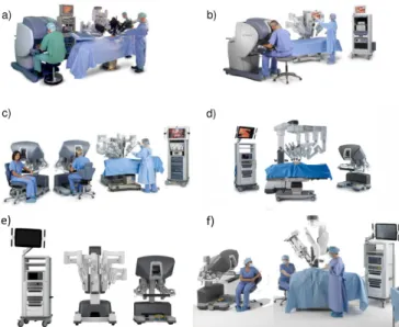
Fig. 1. The 6 generations of the da Vinci Surgical System; a) da Vinci Classic, b) da Vinci S, c) da Vinci Si and d) da Vinci Xi, completed with the most recent e) X and f) SP systems. Image credit: Intuitive Surgical Inc.
more intuitive instrument control, rescaled motion and some low-level safety functions, such as tremor filtering [2]. The market leader RAMIS system is the da Vinci Surgical System (Intuitive Surgical Inc. Sunnyvale, CA), which received FDA clearance in 2000. Since then, six generations appeared of the robot, following the same control principle [3] (Fig. 1). Due to the fact that RAMIS systems offer various benefits, there are over one million successful RAMIS procedures performed a year [4].
Nevertheless, some limitations of RAMIS remains. The endoscopic camera mounted on the Endoscopic Camera Ma-
nipulator (ECM) is controlled by the surgeon through foot pedals by default, which presents a cognitive load [5]. It still poses a major risk when the surgical tools are not in the field- of-view of the camera, the tissues can easily be damaged by the tools. The camera is controlled by the surgeon through foot pedals by default. A possible solution for reducing the risk associated with the manual control is the autonomous positioning of the endoscopic camera. Detecting and following the movements of the Patient Side Manipulators (PSMs) can be achieved by eye-in-hand visual servoing algorithms using the frames of the endoscopic camera [6].
In this paper, we propose an open-source software solution for visual servoing for camera control of a da Vinci classic with Da Vinci Research Kit (DVRK) [7]. During the research, the main goal was to extend the iRob Surgical Automation Framework (irob-saf) [8] with visual servoing for the ECM. The technique of visual servoing uses visual feedback to control the motion of a robot. The automation of the endoscope’s motion can by achieved utilizing visual servoing, by the means of the ECM follows the movements of the PSMs, therefore the surgical tools are always in the field-of view of the camera. Developing the open-source software solution for visual servoing for camera control of a da Vinci classic means creating a more autonomous system for da Vinci, which is considered to be at Level of Autonomy 2 (LoA 2) [4]. At LoA 2, the system is trusted to complete certain tasks or sub-tasks in an autonomous manner, such as suturing or blunt dissection.
The visual servoing feature of the proposed framework can assist through various parts of the whole surgery, and its tasks do not involve decision making. In this recent work, we focus mainly on the visual servoing robot control, thus we used a marker-based tool detection. We validated our method on a the DVRK system at ´Obuda University.
II. METHODS
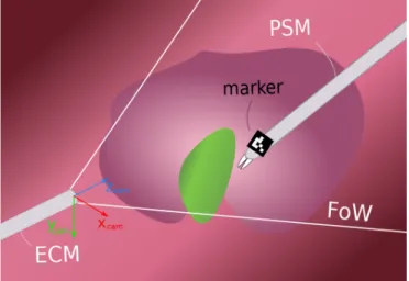
Our proposed method uses eye-in-hand visual servoing approach; it allows the autonomous movements of the camera by receiving an excepted goal function (expected view). The method uses stereoscopic images as an input, the positioning of the ECM operates in 3D. The tool detection was achieved via ArUco codes (marker-based detection) placed on the PSM [9]. The schematic figure of the setup is presented in Fig. 2.
A. Software Frameworks
a) Robot Operating System: The Robot Operating Sys- tem1 (ROS) is a flexible framework for the modular develop- ment of robot software [10]. It is a collection of functions, libraries and conventions, aiming to simplify the development of complex and robust robot applications across a wide variety of platforms. It consists of nodes, which are responsible for specific functions. Those communicate with each other via messages though channels called topics. The messages are specific data structures serving various purposes.
1https://www.ros.org/
Fig. 2. The setup of theirob-safwith visual servoing: The eye-in-hand visual servoing can be executed if the PSMs (detected with markers) are in the field-of-view (FoW) of the ECM.
b) Da Vinci Research Kit: DVRK is a set of open-source, custom-built hardware controllers and software elements to make possible the programming of the attached da Vinci arms, developed for researchers [7]. Amongst other methods the DVRK offers ROS interface to the arms, overriding the original control of the da Vinci; this interface was used to control the ECM.
c) IROB Surgical Automation Framework: The purpose of the irob-saf2 is to facilitate automation of surgical subtasks for the da Vinci Surgical System with the DVRK, of- fering a modular architecture with built-in functionalities, like parameterizable surgemes, interface to the DVRK or computer vision algorithms and image pipeline from the endoscope [8].
In this research, the goal was to extend the irob-safwith depth-inclusive visual servoing for the ECM.
B. Architecture of theirob-safwith visual servoing The architecture of theirob-safwith visual servoing is presented in Fig. 3. The nodes of the developed system can be divided into two domains—visual and motion. These two domains are communicating through the main node, called subtask logic, containing the high-level implementation of the specific subtask.
The visual domain is basically an image processing pipeline, highly relying on the built-in stereo vision capabilities of ROS34. On the lowest level, the stereo video stream from the endoscope, captured by a Blackmagic DeckLink frame grabber card5, is received by a built-in ArUco detector node ofirob-saf. The result of this node is further processed by the node calculates the 3D position of the marker. This 3D position is received by the subtask logic node, and used for the manipulation of the endoscope.
2https://github.com/ABC-iRobotics/irob-saf
3http://wiki.ros.org/stereo image proc
4http://wiki.ros.org/stereo image proc
5https://www.blackmagicdesign.com/products/decklink
Fig. 3. The hierarchic structure of theirob-safwith visual servoing: the visual domain provides the 3D coordinate of the marker from the stereo video stream; the motion domain synthesize the motion and execute it.
The motion domain is built in a hierarchic structure; on the top level, the node is called the surgeme server, containing the implementation of surgical gestures, such as cutting or grasping. Below thesurgeme server, therobot server node is performing high-level robot control tasks, such as following a trajectory. Therobot serveris connected to the ROS interface of the DVRK, reliable for the low-level control of the arms.
C. Extraction of the Instrument Position
As mentioned above, ROS offers extensive stereo vision support, from stereo camera calibration to the calculation of the 3D point cloud of the scene. Utilizing this infrastructre the 3D position of the ArUco marker is calculated as follows.
The image coordinates of the corners of the detected ArUco marker is received alongside the 3D point cloud calculated by ROS. The image coordinates of the marker’s center is then calculated from the received corners; these coordinates are used to extract the marker’s 3D position from the point cloud using the Point Cloud Library (PCL)6. The 3D position of the marker is published to the subtask level node.
D. Robot Control with Visual Servoing
The purpose of the developed visual servoing algorithm is to keep the tracked surgical instrument within the bounds of the endoscopic camera image, while avoiding unnecessary movements of the ECM, as it might disturb the surgeon.
Thus, instead of implementing a controller that would keep the instrument in the center of the image by constantly adjusting the ECM pose, the following approach was utilized. The desired position of the instrument (D) and a distance threshold (t) are to be defined in the camera frame (Fig. 2) by the user;
the position of the instrument (currently and ArUco marker,
6https://pointclouds.org/
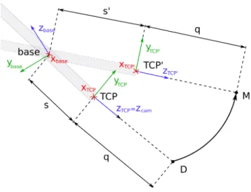
Fig. 4. The concept of following the instrument using visual servoing on the da Vinci surgical System. TheT CP0 pose of the Endoscopic Camera Manipulator (ECM) to be calculated, so the instrument is seen at the desired position in the camera image.
M) is tracked by the stereo camera of the ECM (Fig. 4). If the distance of the instrument and the desired position exceeds the thresholdt in any direction, the ECM is moved to a new pose (T CP0), where the instrument’s position in the camera frame is the same as the desired position; it is in the center of the image again. The poseT CP0 is calculated as follows.
The motion of the ECM is restricted in a way so that at the point of insertion (inside the trocar) lateral motion is not possible; it would potentially harm the patient. This point is the so-called Remote Center of Motion (RCM), which is also the origin of thebaseframe of the ECM (Fig. 4). Due to this lateral restriction, the ECM has 4 Degrees of Freedom (DoF):
pivot around the RCM, insertion and rotation along the shaft.
The position of pointsD andM is defined/measured in the coordinate frame of the camera (cam, Fig. 2). As the marker is intended to keep near the center of the camera image, in distance q—defined by the surgeon or the assistance—from the camera (Fig. 4), the homogeneous coordinates of desired position of the marker is written as follows:
dcam =
0 0 q 1T
. (1)
To calculate the newT CP0 pose, the coordinates of those points need to be converted to the T CP frame (Fig. 4). In the case of a 0 degree endoscope, this—by neglecting the displacement of the the camera along axis x—is simply aπ rotation around axisx, with homogeneous transformation:
TT CP,cam=
1 0 0 0
0 −1 0 0 0 0 −1 0
0 0 0 1
. (2)
Then, the coordinates of the points D and M in thebase frame are calculated using the position and orientation of
T CP, received from the DVRK, converted to homogeneous transformation TT CP,base.
Thanks to the ECM’s restricted form of motion, the calcu- lation of the pose T CP0 gravely simplifies by conversion to a spherical coordinate system around the origin of the base frame. Defining the spherical coordinates of the pointsDand M in the base frame would easily result in inclination π, as those points are typically located in the vicinity of the elongation of axis zbase (Fig. 4). If the inclination is 0 or π, the azimuthal angle is arbitrary; that ambiguity is to be avoided in this application. Thus, the frame of the spherical coordinate system (sph) is rotated byπ/2 along axisx:
Tsph,base =
1 0 0 0
0 0 −1 0
0 1 0 0
0 0 0 1
. (3)
The homogeneous coordinates of points D and M in the frame sphare then calculated by
dsph=Tsph,base·T−1T CP,base·TT CP,cam·dcam (4) and
msph=Tsph,base·T−1T CP,base·TT CP,cam·mcam (5) consecutively, where dcam and mcam are the homogeneous coordinates in the camera frame. The spherical coordinates r (radial distance), θ (inclination) and φ (azimuthal angle) of those points are calculated by the following formulae:
r=p
x2+y2+z2, (6)
φ= arctan2(y, x), (7)
θ= arccosz
r. (8)
By knowing the spherical coordinates of the desired and the current tool locations, the difference of those coordinates can be used to get the transformation from T CP to T CP0. The angular differences
∆φ=φM −φD; (9)
∆θ=θD−θM (10)
corresponding to the rotation from T CP to T CP0, and distance
∆r=rM −rD (11)
corresponding to the insertion of the endoscope, are defined.
Important to note that the ∆θ is intentionally defined with opposite sign, as the the direction of the inclination angle is opposite to the rotation defined by axis x.
From the spherical coordinates it is easy to see that the required length of the ECM’s insertion, that ensure the q
distance from the tracked instrument, iss0=s+ ∆r, wheres is the current length of insertion (Fig. 4). The vector for this translational movement is calculated as follows:
tT CP =
0 0 ∆rT
; (12)
tbase=RT CP,base·tz,T CP, (13) where RT CP,base is the rotational part of TT CP,base. The homogeneous matrix for this translation is:
Tr=
I tbase
0 1
. (14)
As the azimuthal angle defines a rotation around axisz, and the inclination a rotation around axisx, the required rotations from the differences are written:
Taz=
1 0 0 0
0 cos(∆θ) −sin(∆θ) 0 0 sin(∆θ) cos(∆θ) 0
0 0 0 1
. (15)
Similarly, as inclination defines the rotation along axisz:
Tinc=
cos(∆φ) −sin(∆φ) 0 0 sin(∆φ) cos(∆φ) 0 0
0 0 1 0
0 0 0 1
. (16)
Finally, using these transformations the desired pose of the ECM T CP0 is calculated:
TT CP0,base=T−1sph,base·Tinc·Taz·Tsph,base·Tr·TT CP,base. (17) Using the desired pose of the ECM a Cartesian trajectory is generated and being sent to the controller to move the ECM into that pose; positions are generated by linear interpolation, the orientation by spherical linear interpolation (Slerp) [11], offered by the Eigen C++ library7.
III. RESULTS
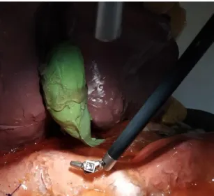
To validate the proposed visual servoing method, experi- mental scenarios were set up, where the measurement of the accuracy were aimed. The tests on the da Vinci Surgical Sys- tem were done in DVRK teleoperated mode with a phantom representing a gallbladder and its environment. During the test setups, the arms are controlled from the master side by an operator, except the ECM, which was moved autonomously by the proposed method. The anatomically correct surgical phantom (originally created for modeling laparoscopic chole- cystectomy) provided the background for the tests, and an ArUco code was placed on the moving PSM (Fig. 5). To determine the accuracy of the system, the ArUco marked PSM was moved in x, y and z directions by the operator.
The Cartesian position of the ECM alongside the joint angles
7http://eigen.tuxfamily.org
Fig. 5. Testing the proposed visual servoing method on the da Vinci Research Kit. An ArUco code was fixed on a surgical tool for instrument tracking, and the endoscope followed the tool’s displacements. The tests were done in a surgical phantom environment.
related to yaw, pitch and insertion of the endoscope were tracked, then shown in the graphs to easily determine if the created system functions properly. In the experiments, the endoscopic camera of the da Vinci was used with the original 640 × 480 pixels resolution camera of the da Vinci Classic.
First, an experiment of one instrument, with an attached ArUco marker moving in the xaxis of the coordinate frame of the camera was performed. The results of the distance from the desired position in the x direction, the yaw angle and x component of the ECM’s Cartesian position are shown in Fig. 6.
Similarly, in the second experiment the marked instrument was moved along the y axis of the coordinate frame of the camera, while additionally to the marker’s distance from the
Fig. 6. One-marker setup forxaxis experimentn. The red horizontal lines are the given threshold value for the displacement length.
Fig. 7. One-marker setup foryaxis experiment. The red horizontal lines are the given threshold value for the displacement length.
desired pose in this direction the pitchand the y component of the ECM’s Cartesian position are recorded (Fig. 7).
In the third experiment, the instrument was moved along the z axis of the coordinate frame of the camera; apart from the z component of the distance of the marker from the desired position and z component of the position of the ECM, the value of theinsertion joint were captured (Fig. 8).
In Fig. 6, 7 and 8, the distance threshold value of±20mm is marked with red horizontal lines. The two threshold lines determine a limited area corresponding to the ideal point, where the ECM does not move. Outside this area, the ECM performs its corrections to reach the desired point determined by the thresholds as shown in those figures. The desired values along both axesxandy were 0 (corresponding to the center of the image), and 30 mm along z axis (corresponding to 30mm distance from the camera).
The data of three graphs above are shown together, along-
Fig. 8. One-marker setup forzaxis experiment. The red horizontal lines are the given threshold value for the displacement length.
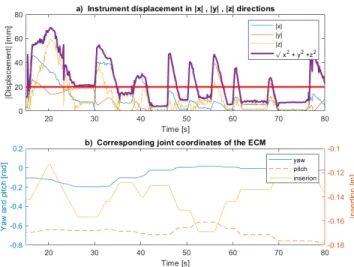
Fig. 9. One-marker setup for all directions shown in one graph. The red horizontal line is the given absolute threshold value for the displacement length. The purple line is the Euclidean distance of the marker from the desired point.
side the Euclidean distance from the desired position in Fig. 9, where the relationship between the directions of the marker’s displacement and the changing of corresponding joint coordi- nates can be observed. In Fig. 9a, the absolute value of the instrument displacement in x, y, z directions are shown with the Euclidean distance of the marker from the desired point.
In Fig. 9b, corresponding joint coordinates of the ECM(yaw, pitch, insertion) are shown. It the instrument displacement in x direction is higher than the set threshold, the corresponding joint coordinate of the ECM, the yaw will alter. Similarly, the pitch corrects the instrument displacement in y direction, and the instertion corrects the instrument displacement in z direction. If the movements in the experiments were complex, two or more joints were moving in the given interval.
IV. LIMITATIONS ANDFURTHERWORKS
This recent study focused mainly on robot control, however, advanced computer vision-based, marker-less approaches are expected in the clinical practice. Instrument segmentation in RAMIS is a well-studied area, most of the recently proposed methods are Deep Neural Network-based solutions [12], [13].
In our future work, we intend to add existing marker-less instrument segmentation implementations. Another limitation of the system is the one marker-based approach; in the medical practice, two or more instruments are often used. To keep two instruments in the visual scene, we have to extend our method to handle this, especially in the case when the two tools are moving to different directions. In this work, we used a0degree endoscope; however, 30 degree endoscopes are often used in RAMIS. In our future work the case of different endoscope geometries will also be considered.
V. CONCLUSION
In this work, we proposed a marker-based visual servoing method for Robot-Assisted Minimally Invasive Surgery to
automate camera moving, which can help the surgeon focusing only on the instrument control in DVRK enhanced research mode. We tested our method on the da Vinci Surgical System.
The usage of visual markers ensured the elimination of a significant fraction of vision-related errors, thus during the development and validation the main focus could remain on the robot control aspect of the visual servoing problem. The outcome showed that the framework can be considered a reliable base for future work. Further development needs to be done to extend the work, such as advanced computer vision- based tool detection and multiple instruments tracking.
ACKNOWLEDGMENT
R. Nagyn´e Elek, T. D. Nagy and T. Haidegger are supported through the New National Excellence Program of the Ministry of Human Capacities. This work was partially supported by ACMIT (Austrian Center for Medical Innovation and Tech- nology), which is funded within the scope of the COMET (Competence Centers for Excellent Technologies) program of the Austrian Government. T. Haidegger is a Bolyai Fellow of the Hungarian Academy of Sciences.
REFERENCES
[1] L. J. Freeman, “Method for minimally invasive surgery in the digestive system,” Patent, 2003.
[2] ´A. Tak´acs, D. ´A. Nagy, I. J. Rudas, and T. Haidegger, “Origins of Sur- gical Robotics: From Space to the Operating Room,”Acta Polytechnica Hungarica, vol. 13, no. 1, pp. 13–30, 2016.
[3] K. Miller and M. Curet, “Intuitive Surgical: An overview,” inRobotic- Assisted Minimally Invasive Surgery. Springer, 2019, pp. 3–11.
[4] T. Haidegger, “Autonomy for Surgical Robots: Concepts and Paradigms,”IEEE Trans. on Medical Robotics and Bionics, vol. 1, no. 2, pp. 65–76, 2019.
[5] R. Nagyn´e Elek and T. Haidegger, “Robot-Assisted Minimally Inva- sive Surgical Skill Assessment—Manual and Automated Platforms,”
Acta Polytechnica Hungarica, Special Issue on Platforms for Medical Robotics Research, vol. 16, no. 8, pp. 141–169, Sep. 2019.
[6] S. Hutchinson, G. Hager, and P. Corke, “A tutorial on visual servo control,”IEEE Transactions on Robotics and Automation, vol. 12, no. 5, pp. 651–670, Oct. 1996.
[7] P. Kazanzides, Z. Chen, A. Deguet, G. S. Fischer, R. H. Taylor, and S. P. DiMaio, “An open-source research kit for the da Vinci® Surgical System,” inProc. of the IEEE International Conference on Robotics and Automation, Hong Kong, 2014, pp. 6434–6439.
[8] T. D. Nagy and T. Haidegger, “A DVRK-based Framework for Surgical Subtask Automation,”Acta Polytechnica Hungarica, Special Issue on Platforms for Medical Robotics Research, vol. 16, no. 8, pp. 61–78, 2019.
[9] S. Garrido-Jurado, R. Mu˜noz-Salinas, F. J. Madrid-Cuevas, and M. J.
Mar´ın-Jim´enez, “Automatic generation and detection of highly reliable fiducial markers under occlusion,”Pattern Recognition, vol. 47, no. 6, pp. 2280–2292, 2014.
[10] M. Quigley, B. Gerkey, K. Conley, J. Faust, T. Foote, J. Leibs, E. Berger, R. Wheeler, and A. Ng, “ROS: An open-source Robot Operating System,” in Proc. of the ICRA Workshop on Open Source Software, vol. 3, Kobe, Japan, 2009.
[11] K. Shoemake, “Animating Rotation with Quaternion Curves,” ACM Transactions on Graphics, vol. 19, no. 3, pp. 245–254, 1985.
[12] T. Mikada, T. Kanno, T. Kawase, T. Miyazaki, and K. Kawashima,
“Three-dimensional posture estimation of robot forceps using endoscope with convolutional neural network,”The International Journal of Med- ical Robotics and Computer Assisted Surgery, p. e2062, Jan. 2020.
[13] J. Zhang and X. Gao, “Object extraction via deep learning-based marker- free tracking framework of surgical instruments for laparoscope-holder robots,” International Journal of Computer Assisted Radiology and Surgery, Jun. 2020.