Au/Pb Interface Allows the Methane Formation Pathway in Carbon Dioxide Electroreduction
Ahmed Mohsen Ismail, Gergely F. Samu, Huu Chuong Nguyën, Edit Csapó, Núria López, and Csaba Janáky*
Cite This:ACS Catal.2020, 10, 5681−5690 Read Online
ACCESS
Metrics & More Article Recommendations*
sı Supporting InformationABSTRACT: The electrochemical conversion of carbon dioxide (CO2) to high-value chemicals is an attractive approach to create an artificial carbon cycle. Tuning the activity and product selectivity while maintaining long-term stability, however, remains a significant challenge. Here, we study a series of Au−Pb bimetallic electrocatalysts with different Au/Pb interfaces, generating carbon monoxide (CO), formic acid (HCOOH), and methane (CH4) as CO2reduction products. The formation of CH4is significant because it has only been observed on very few Cu-free electrodes. The maximum CH4 formation rate of 0.33 mA cm−2 was achieved when the most Au/Pb interfaces were present. In situ Raman spectroelectrochemical
studies confirmed the stability of the Pb native substoichiometric oxide under the reduction conditions on the Au−Pb catalyst, which seems to be a major contributor to CH4formation. Density functional theory simulations showed that without Au, the reaction would get stuck on the COOH intermediate, and without O, the reaction would not evolve further than the CHOH intermediate. In addition, they confirmed that the Au/Pb bimetallic interface (together with the subsurface oxygen in the model) possesses a moderate binding strength for the key intermediates, which is indeed necessary for the CH4 pathway. Overall, this study demonstrates how bimetallic nanoparticles can be employed to overcome scaling relations in the CO2reduction reaction.
KEYWORDS: CO2reduction reaction, solar chemicals, solar fuels, bimetallic catalysts, DFT
■
INTRODUCTIONTraditional fossil fuels still occupy a leading position in today’s energy structure. Carbon dioxide (CO2) emissions generated via combustion of fossil energy resources lead to global climate change. Conversion of CO2into valuable fuels and chemicals that can act as energy carriers is a promising route to create an artificial and sustainable carbon cycle.1−3The electrochemical CO2 reduction reaction (CO2RR) is an attractive approach because of its mild operation conditions and the wide range of carbon-based products which can be produced by controlling the reaction conditions. Furthermore, it offers a way to store electricity generated from renewable green energy sources such as solar and wind.4−6 CO2RR in an aqueous environment, however, is rather complicated because of substantial kinetic barriers, especially, if we compare to water-splitting.4 There- fore, developing electrocatalysts with high efficiency, selectiv- ity, and long-term stability is a crucial step of great urgency toward industrialization.7,8
The 2e−products (CO and HCOOH) are rather easy to be produced with high Faradaic efficiency (FE) (close to 100%).
Several transition metals (such as Au9,10and Ag11) and p-block metals (such as Sn12and Pb13) are good catalysts in this vein.
Going beyond 2e− products is much more challenging. The product distribution on different metal electrodes mostly depends on the binding energy of CO.14,15Copper is the only metal having an intermediate binding energy for CO and thus can catalyze the CO2 reduction to hydrocarbons and
alcohols.16,17 Most Cu surfaces, however, suffer from poor selectivity. A wide range of C1−C3products can be generated, including major products (CO, HCOOH, methane, and ethylene), intermediate products (ethanol, propanol, and allyl alcohol), and minor products (methanol, glycolaldehyde, acetaldehyde, acetic acid, ethylene glycol, propionaldehyde, acetone, and hydroxyacetone).18The rich redox chemistry of Cu makes the picture even murkier: the reduction of the partially oxidized layer under electrochemical reduction conditions leads to the formation of defect sites and irreversible reconstruction of the Cu surface, which results in varying catalytic activity and selectivity.19 For example, a commercial Cu foil showed a total current density of−10 mA cm−2after 2 min of electrolysis, which later declined to−1 mA cm−2. FECOdecreased gradually from 25% during thefirst hour to 10% over 7 h, and the majority of current was due to the hydrogen evolution reaction (HER).17
Moving beyond pure metals, bimetallic nanoparticles (NPs) provide an ideal platform for studying the effect of surface composition20−25 and to identify how to bypass scaling
Received: February 13, 2020 Revised: April 11, 2020 Published: April 14, 2020
Research Article pubs.acs.org/acscatalysis
License, which permits unrestricted use, distribution and reproduction in any medium, provided the author and source are cited.
Downloaded via UNIV OF SZEGED on June 24, 2020 at 13:26:02 (UTC). See https://pubs.acs.org/sharingguidelines for options on how to legitimately share published articles.
and tested. Ni5Ga3 alloy catalyzed the formation of CH4, C2H4, and C2H6with a total FE of about 4%. Ni3Al and Ni3Ga intermetallic compounds also generated C2and C3products.33 In another study, the shell thickness dependence of the product distribution was investigated on Pd@Au core−shell NPs. As the thickness of the Pd shell increased from 1 to 10 nm, HCOOH, CH4, and C2H4were generated in addition to CO and H2.34Finally, it was reported that pulse-deposited Zn dendrites on a Ag foam catalyzed the formation of methanol with a FE ≥ 10.5% at a total current density of −2.7 mA cm−2.35
Synthesis of bimetallic electrodes containing p-block metals (such as Sn, In, and Pb, all having high H2overpotential and favoring HCOOH production) is a good strategy not only to tune the CO2RR activity and selectivity but also to suppress the HER.13,36,37A Sn/SnOxelectrode exhibited 8-fold higher partial current density and 4-fold higher FE for the CO2RR than the respective Sn foil.12Oxide-derived Pb showed up to 700 times lower H+ reduction activity compared to the Pb foil.13Such a low activity was explained by the presence of a thin and metastable surface oxide/hydroxide layer that passivates the surface for HER but is active for CO2RR over prolonged electrolysis. In our previous work, we highlighted the effect of phase composition of Au−Sn bimetallic NPs on the CO2RR performance.20 Two high-value products were formed: HCOOH and syngas with a tunable ratio. The AuSn phase showed the lowest overpotential for the CO2RR, and Raman spectroelectrochemistry confirmed the generation of formate anions on the AuSn phase at a notably less negative potential compared to the pure Sn electrode.20 Still, beyond the above examples, the combinations of other p-block metals with Au (as a CO-producing metal) have not been reported as Cu-free catalyst alternatives.
Here, we uncover how the presence of Au/Pb interfaces affect the electrocatalytic activity of Au-decorated Pb bimetallic NPs toward CO2reduction. Most importantly, the formation of CH4was demonstrated on the Au−Pb catalysts unlike on Au, Pb, or even their physical mixture. Both experimental studies and density functional theory (DFT) simulations indicated that the presence of (subsurface) oxygen associated with Pb together with the existence of the Pb/Au interface are crucial to provide proper sites along the pathway for the CO2 conversion to CH4.
■
EXPERIMENTAL SECTIONMaterials. Gold(III) chloride trihydrate (HAuCl4·3H2O, 99.9%, Aldrich), lead(II) nitrate [Pb(NO3)2,≥99.0%, AnalaR NORMAPUR, Reag. Ph. Eur., ACS], sodium citrate dihydrate (C6H5Na3O7·2H2O 99%, Aldrich), polyvinylpyrrolidone (PVP, MW= 40,000, Aldrich),L-ascorbic acid (C6H8O6≥99%, ACS
Au precursor. In a typical procedure for the synthesis of Au50Pb50, 0.05 g of Pb(NO3)2was added to 30 cm3 of (0.25 mM) PVP. The solution was stirred under a nitrogen atmosphere in a 100 cm3 round-bottomed flask for 20 min.
Subsequently, 20 cm3(50 mM) of NaBH4was added using a syringe pump at a rate of 0.2 cm3 min−1. The solution was stirred for another 1 h to complete the reaction and decompose the remaining NaBH4. Next, 6 cm3(100 mM) of ascorbic acid was added, and the mixture temperature was adjusted to 50°C. Then, 30 cm3of (5 mM) HAuCl4solution was injected using a syringe pump at a rate of 0.2 cm3min−1. The solution was left stirring for 30 min and then allowed to cool down. The product was collected by centrifugation at 10,000 rpm for 20 min and washed with ethanol/water mixture and then dried under nitrogen. Other compositions of Au−Pb bimetallic NPs were synthesized by changing the amount of Au precursor.
Synthesis of Au NPs. Au NPs were prepared using an adopted method.22 Briefly, 100 cm3 (0.25 mM) of HAuCl4 solution was heated to boiling under moderate stirring. Then, 0.7 cm3of 0.23 M sodium citrate was added, and the solution color turned to wine red within a few seconds. The solution was boiled for a further 15 min and then allowed to cool down to room temperature.
Synthesis of Pb NPs.For the preparation of Pb NPs, 0.09 g of Pb(NO3)2 and 0.5 g PVP were added to 50 cm3 of ultrapure water in a 100 cm3 round-bottomed flask. The solution was stirred under a nitrogen atmosphere for 20 min.
Subsequently, 40 cm3(50 mM) of NaBH4was added using a syringe pump at a rate of 0.2 cm3 min−1. The solution was stirred for another 30 min to complete the reaction. The product was collected by centrifugation at 9000 rpm for 20 min and washed with ethanol and then dried under nitrogen.
Synthesis of Pb-Decorated Au NPs (Pb95Au5 NPs).
PVP (0.5 g) was added to 50 cm3(0.25 mM) of premade Au NPs in a 250 cm3 round-bottomedflask and stirred at room temperature for 4 h. Then, 2 cm3of 0.14 M Pb(NO3)2 was added and stirred under nitrogen. After 30 min, 30 cm3of (50 mM) of NaBH4was added using a syringe pump at a rate of 0.2 cm3min−1. The stirring was continued for an additional 1 h; then, the particles were collected by centrifugation at 10,000 rpm for 20 min and washed with ethanol/water mixture and then dried under nitrogen. A detailed description of the synthesis of Au seeds is given in theSupporting Information.
Physical Characterization. X-ray diffraction (XRD) patterns were obtained by a Bruker D8 ADVANCE X-ray diffractometer using Cu Kα(λ= 1.5418 Å) radiation in the 2θ range of 10−80°with a scan rate of 0.4°min−1. Transmission electron microscopy (TEM) images were collected on a FEI Tecnai G220 X-Twin microscope working at an accelerating
voltage of 200 kV. A scanning electron microscope (SEM, Hitachi S-4700 field emission) equipped with an energy- dispersive X-ray (EDX) unit was used for elemental analysis.
X-ray photoelectron spectroscopy (XPS) was performed with a SPECS instrument equipped with a PHOIBOS 150 MCD 9 hemispherical analyzer. The analyzer was in the FAT mode with 20 eV pass energy. The Al Kαradiation (hν= 1486.6 eV) of a dual anode X-ray gun was used as an excitation source and operated at 150 W power. Ten scans were averaged to get a single high-resolution spectrum. Charge neutralization was carried out during spectra acquisition, where the position and width of the adventitious carbon peak were monitored. The adventitious carbon peak was at 284.8 eV in all cases. Ar+ sputtering was carried out to remove the upper layers of the sample, where specified. The Ar+ ion gun was operated at 1.2 kV for 10 min. For spectrum evaluation, CasaXPS commercial software package was used.
Electrode Preparation.Suspensions of the samples were prepared by dispersing the powders in isopropanol (5 mg cm−3). Ultrasonic agitation was used to homogenize the suspension for 30 min. Then, the samples were spray-coated to a preheated (110°C) glassy carbon electrode using an Alder AD320 type airbrush and a homemade spray-coater robot, operated with 1 bar compressed nitrogen. The obtained layers were subjected to heat treatment in Argon and air atmospheres at 280 °C to alter the quantity of Pb oxide species and to remove any traces of the solvent. The Au-coated electrodes were prepared by drop-casting an aqueous concentrated dispersion to a heated glassy carbon electrode (80 °C). A loading of 0.48 mg cm−2was employed in the experiments.
Electrochemical Measurements and Product Anal- ysis.All electrochemical measurements were performed using a Metrohm Autolab PGSTAT204 type potentiostat/galvano- stat. A typical three-electrode gastight two-compartment electrochemical cell was used to characterize the catalytic
performance, separated by a Nafion-117 proton exchange membrane. A platinum foil (Alfa Aesar, 99.99%) and Ag/AgCl (3 M NaCl) were used as the counter electrode and the reference electrode, respectively. The measured potentials were converted to the reversible hydrogen electrode (RHE) scale usingERHE= EAg/AgCl+ 0.210 V + 0.0591×pH. All currents are presented after normalization to the geometric surface area of the electrodes. Each compartment was filled with 0.5 M KHCO3solution. The cathode compartment had a∼25 cm3 headspace and contained 35 cm3 of the electrolyte. Before electrolysis, the electrolyte in each compartment was purged with CO2 gas for 30 min. The pH of the electrolyte was 7.2 after saturation, at the beginning of the measurements. The electrolyte in the cathodic compartment was stirred with a magnetic stirrer at a rate of 1000 rpm. The effluent gas from the headspace of the cathode compartment was fed into the online sampling loop of the gas chromatograph (GC) every 30 min for quantification of gas-phase CO2reduction products. A SHIMADZU GC-2010 plus instrument (with ShinCarbon ST column) was used, which was equipped with a BID detector.
Helium gas (99.9999%) was employed as the carrier gas. The liquid product was collected at the same time when GC analysis was performed and was analyzed by nuclear magnetic resonance spectroscopy (Bruker ADVANCE Neo 500).
Phenol and dimethyl sulfoxide were used as internal standards.
The one-dimensional 1H spectrum was measured using a solvent presaturation method to suppress the water peak. The area ratio of the formic acid peak to the phenol peak was compared to the standard curve to quantify the formate concentration. FE values were determined from the charge passed to produce each product by dividing it by the total charge.
In Situ Raman Spectroelectrochemistry.Raman spectra were recorded with a SENTERRA II Compact Raman microscope using 532 nm laser excitation wavelength with Figure 1.(A) XRD patterns of Au−Pb NPs and the parent metals. These marks indicate the diffractions corresponding to the respective crystal phases in the samples: (diamond solid)α-PbO2(JCPDS no. 75-2414), (phi)α-PbO (JPDS no. 78-1666), (circle solid) Pb (dot line) (JCPDS no.
02-0799), and (delta) Au (JCPDS no. 04-0784). TEM images of (B) Au5Pb95, (C) Au20Pb80, (D) Au50Pb50NPs, and (E) single particle of Au5Pb95, showing lattice fringes with adspacing of 0.23 nm corresponding to the (111) plane of face-centered cubic Au, which are located around a core, that features lattice fringes with adspacing of 0.31 and 0.28 nm corresponding to (101) and (111) planes ofα-PbO and Pb, respectively. The nominal compositions were used for the notation of the Au−Pb bimetallic system.
pseudopotentials and an energy cutoffof the plane waves of 450 eV. Bulk calculations were done with a 3×3 ×3 k- point sampling, whereas slabs were calculated with 3×3×1.
After geometry optimization of the bulks Au, Pb, Au2Pb, and PbAu2, slab calculations were performed with dipole corrections, and van der Waals interactions were included with DFT-D2. For each alloy, the low index surfaces (100, 101, 111, 110, and 001) were investigated. The representation of the diluted alloy Au (3%) in the Pb structure was done by substitution of the Pb site with Au. The choice of using a surface with 3% Au concentration in the simulation instead of the experimental 5% was due to the computational efficiency.
Oxide contributions were analyzed by adding O either on the surface or subsurface position. Subsequent CO2 reduction calculations were performed on the most stable surfaces. The computational hydrogen electrode46−48was used for modelling the CO2reduction49and to compute the Gibbs free energies of the reaction. Thefinal results of PbAu 3% are consistent with larger systems on a 2×2 supercell atγpoint with an Au island instead of a single atom.
Additional geometrical structures can be seen in the Supporting Information in Figures S21−S28. All structures can be accessed at the ioChem-BD database50 under the following link:https://10.19061/iochem-bd-1-167.
■
RESULTS AND DISCUSSIONXRD measurements were carried out to determine the crystal structure of the Au−Pb NPs. Pure Pb showed diffraction peaks at 2θ= 31.36, 36.34, 52.26, 62.26, and 65.33°, corresponding to the face-centered cubic phase of Pb, and peaks at 2θ = 28.68, 35.74, 44.41, and 54.93°for PbO as well as reflections for PbO2at 25.43 and 48.88°(Figure 1A). The intensities of Pb, PbO, and PbO2 peaks decreased notably with increasing Au concentration to 20%, whereas the Au phase became more prevalent on further increasing the Au content (sample Au50Pb50). Pure Au exhibited a face-centered cubic phase.
Importantly, these bimetallic samples are not alloys (but rather particles containing nanosized domains of both metals);
therefore, there is no shift in the reflection positions with an increase of the Au content (unlike e.g., in the case of Ag−Au alloys22). Notably, the small relative intensity of the Pb-related diffractions suggests that the majority of these species are present in an amorphous phase (e.g., nonstoichiometric oxide).
TEM images of the as-prepared Au−Pb NPs show Au dots that are well-distributed on the surface of the Pb particles (Figure 1B−D), confirming the suggested formation mechanism. The average size of the bimetallic particles was 42± 5 nm for all compositions, slightly higher than that of pure Pb NPs 40± 3.5 nm (Figures S1 and S2). For the Au5Pb95sample, which has the lowest Au content, the deposited Au NPs mainly
(Figure S6). The relative amount of the native Pb oxide (PbOx) decreased from 94% to 91% to 72% in the series of the samples with increasing Au content (see alsoTable S1). The Au50Pb50 NPs heated in air exhibited only a Pb 4f peak at 138.45 eV (Figure 2) that corresponds to Pb4+/2+, which is
likely due to the native oxide layer.13 Besides, the lattice oxygen, carbonate, and hydroxide-related oxygen were also detected (seeFigure S7). Although discussed in detail below, we mention here that after a 10 h electrolysis experiment, there was no shift in the Pb 4f peak, indicating no change in the oxidation state. The percentage of PbOxdecreased from 77 to 70%, and the Au content increased from 23 to 30%. When mild Ar+sputtering was employed, the metallic Pb04f peak at 136.86 eV became visible, and the amount of lattice oxygen increased at the expense of carbonate (Figure S7). This confirms the presence of metallic Pb and some non- stoichiometric PbOx structure beneath the surface layer.
EDX data describing the bulk composition are listed in Table S1together with the surface composition obtained from XPS.
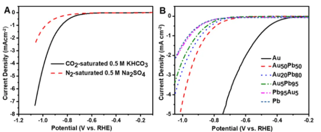
CO2electroreduction was investigatedfirst by linear sweep voltammetry (LSV) to identify the onset potential of the electrochemical process. LSV curves were recorded in CO2- saturated 0.5 M KHCO3(pH = 7.2) and N2-saturated 0.5 M Na2SO4(pH = 7.5) to ensure a similar pH. The onset potential recorded in the CO2-saturated solution was less negative compared to that in the absence of CO2(E=−0.73 V in CO2 Figure 2.High-resolution XPS spectra of the Pb 4f peaks for the Au50Pb50catalyst before and after CO2electrolysis in CO2-saturated 0.5 M KHCO3(pH = 7.2) at−1.07 V vs RHE for 1 h and after Ar+ sputtering.
vs−0.88 V in N2vs RHE, seeFigures 3A andS8 and S9). This indicates that in the CO2-saturated electrolyte, an additional process occurs at a less negative potential besides the HER.20 The comparison of the voltammetric curves of the different Au−Pb NPs is presented inFigure 3B. There is a well-defined trend in the onset potentials with the change in their composition. The least negative potential was witnessed for Au and the most negative for Pb (all the bimetallic electrodes lied in between). In the case of the samples heat-treated in Ar, no clear trend was observed, and the onset potential values of the Au-rich catalysts (Au50Pb50 and Au20Pb80) were more negative than those recorded for samples heated in Air (Figure S10). This observation can be rationalized by the catalytically active nature of PbOxof sites. Cyclic voltammograms (CVs) were also recorded for all samples. For example, CV traces of the Au20Pb80electrode showed the characteristic oxidation and reduction peaks of both Pb and Au, confirming the presence of both elements on the surface (seeFigure S11and discussion therein).
The CO2reduction performance of the bimetallic NPs was explored under chronoamperometric conditions. Analysis of the electrolysis products confirmed the formation of CH4 (highly reduced C1 product) besides CO and HCOOH, whereas the remaining charge was attributed to the HER. First, we investigated how the potential affects the product distribution. Pure Au produced mainly CO (FE ≥ 70%) with very little dependence on the applied potential, and some minor traces of HCOOH were also detected (Figure S12B).
Pure Pb generated HCOOH and H2, and the maximum FEHCOOHwas 78% at−1.07 V versus RHE, whereas FEH2was 22% (Figure S12D). The current density values recorded for
the Au50Pb50catalyst at different potentials are shown inFigure 4as an example, together with the FE values for the various products. At−1.07 V versus RHE, CH4with a FE of 2.8% was produced. At more negative potentials (−1.17 V vs RHE), we did not observe a further increase in FECH4, but HER activity increased. Three parallel long-term electrolysis experiments were carried out at −1.07 V versus RHE (see an example in Figure 4C). A stable current of −10.8 ± 0.5 mA cm−2 was achieved with CO, HCOOH, and CH4FEs of 25.7±8.0, 25.5
±0.7, and 2.8±0.4%, respectively, during the 3 h electrolysis.
Smaller FE values were seen at the same potential for the Au50Pb50 catalyst heated in Ar (with the parallel rise of the competing HER) for all CO2R reduction products (Figure S13). By changing the composition to Pb95Au5 (Figure S14A,B), low current densities <−0.5 mA cm−2were achieved in the lower cathodic potential region (−0.77 to−0.87 V vs RHE), associated mainly with HER. At potentials more negative than −0.87 V versus RHE, not only the FEHCOOH was increased but also CH4 was produced with 4.8% FE, achieving a FEtotof∼100% (at−1.07 V vs RHE). For Au5Pb95 and Au20Pb80 catalysts (Figure S14C,D), CO was generated with a FE of 1−2% at different potentials. FEHCOOHincreased with increasing potentials, but H2 evolution exhibited an opposite trend on the Au5Pb95electrode. Au20Pb80electrode shows very little dependence of the potential. CH4 was not detected at potentials less negative than−1.07 V versus RHE.
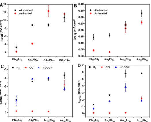
To investigate the effect of electrode composition (especially on CH4formation which represents the reduction process that requires the transfer of eight electrons), we compared the product distribution and partial current densities during CO2 electrolysis at−1.07 V versus RHE. A relatively stable current Figure 3.(A) LSV profiles of Au50Pb50catalyst in CO2-saturated 0.5 M KHCO3(pH = 7.2) and N2-saturated 0.5 M Na2SO4(pH = 7.5); scan rate
= 5 mV s−1. (B) LSV profiles of Au−Pb NPs with different compositions in CO2-saturated 0.5 M KHCO3(pH = 7.2) stabilized after multiple cycles. Scan rate = 5 mV s−1. The layers were heated in the air atmosphere at 280°C. The loading was 0.48 mg cm−2in all cases.
Figure 4.Electrochemical CO2reduction activity of the air-heated Au50Pb50catalyst: (A) Total current density as a function of time at various potentials, (B) H2, CO, HCOOH, and CH4FEs of 1 h CO2electrolysis at different applied potentials, and (C) 3 h CO2electrolysis measured in CO2-saturated 0.5 M KHCO3at−1.07 V vs RHE.
density was measured in all cases, and its value increased with the Au content (Figures 5A and S15). The partial current density for CO production reached −3.2 mA cm−2 on Au50Pb50 heated in air (Figure 5C), whereas for the other catalysts, the CO formation dropped to∼−0.16 mA cm−2.jH2 declined linearly with increasing Pb content, which is characteristic of Pb.51 jCH4 increased from −0.15 to −0.16,
−0.24, and−0.33 mA cm−2 for Pb95Au5, Au5Pb95, Au20Pb80, and Au50Pb50, respectively (Figure 5B). This trend suggests that comparable amounts of Au and Pb are needed at the surface to ensure high reaction rates (see also Table S1).
Importantly, the formation rate of CH4was always higher on samples heated in air compared to their Ar-heated counter- parts.
A 10 h electrolysis was performed at−1.07 V versus RHE to assess the stability of the Au50Pb50 catalyst and verify the continuous production of CH4(Figure S16). The total current
density stabilized at −13 mA cm−2 after 1 h and remained constant. FECH4 varied within 2.8−2.1%. We performed an additional experiment with labeled13CO2and KH13CO3, and the almost exclusive formation of13CH4was verified (deduced from them/z= 17 signal), confirming that the detected CH4 came from CO2 reduction (see Figure S17 and discussion therein).
We also performed a set of controlled experiments in which the electrodes were prepared from a physical mixture of Au and Pb NPs. A physically mixed electrode (60 at. % Au + 40 at.
% Pb) with a composition similar to that of the Au50Pb50 catalyst (as confirmed by EDX analysis, Table S1) was prepared and investigated at−1.07 V versus RHE (Figures S18 and4). A current density of−6 mA cm−2was achieved (note the −10.8 mA cm−2 value recorded for the respective bimetallic catalyst). The CO and CH4 FEs significantly dropped to 2 and <0.5%, respectively, whereas FEHCOOH increased to 50%. This suggests that the interfaces among Figure 5.Electrochemical CO2reduction activity of the Au−Pb catalysts at−1.07 V vs RHE: (A) Total current density and (B) partial current density of CH4as a function of composition. Partial current density of H2, CO, and HCOOH on (C) air-heated catalysts and (D) Ar-heated samples.
Figure 6.Raman spectra collected in CO2-saturated 0.5 M KHCO3as a function of the applied potential (A) on the Au50Pb50catalyst and (B) on pure Pb (dotted lines mark the bands from the substrate). (C) Potential dependence of (C−H-stretch) intensity of formate anion at 2950 cm−1on Au50Pb50and Pb NPs as a function of the applied potential. The potential is versus RHE scale.
the monometallic domains are the plausible active sites for CO2 reduction to CH4. In the Au−Pb system, the monometallic domains are more adjacent through nano- structured Au/Pb interfaces, whereas the physically mixed system contains much less interfaces. We performed a CO electrolysis experiment which yielded CH4 with a 4.9% FE, which is comparable to that observed in CO2reduction. This proves that the bimetallic Au−Pb electrodes can reduce CO and suggests CO to be a key intermediate in the proposed mechanism (seeFigure S19and discussion therein).
To gain further insights into the mechanism of the CO2 reduction process, Raman spectra were collected under electrochemical control. This allows the direct monitoring of both the changes in the chemical nature of the electrocatalysts as well as the formation of certain reaction intermediates and products during the electrolysis.52 The spectra collected between the open circuit-potential and −0.6 V versus RHE exhibit only bands associated with tetragonal PbO (84 and
∼144 cm−1) and orthorhombic PbO (280 cm−1)53and the O− H stretching mode of the adsorbed water (3000−3700 cm−1, this band was almost independent of the potential).52 At a moderate negative potential (−0.8 V vs RHE), new bands appeared, and their intensities show a slight potential dependence (Figure 6A). The PbO bands became more intense and slightly shifted at more negative potentials because of the formation of surface defects as a result of partial reduction (Figure S20A).20,54This shift indicates that the CO2 reduction proceeds at potentials where PbOx is present. At potentials more negative than −1.5 V versus RHE, it was difficult to collect Raman spectra because of intense gas evolution. The bands’ assignment is presented in Figure 6A and summarized inTable S2; a band at 2950 cm−1and several bands of moderate intensity in the region of 900−1715 cm−1 were observed. These bands are similar to those observed during CO2 reduction on Au−Sn bimetallic NPs20 and adsorption of HCOOH on silver colloids and Cu,55,56 indicating the formation of HCOOH and the presence of adsorbed bicarbonate species. The spectra recorded for pure Pb show the formation of PbCO3 at the beginning of the experiment, and there is an instant and considerable decrease in the intensity of the PbO band (Figures 6B and S20B).
Interestingly enough, PbOx seems to be better stabilized on Au−Pb bimetallic surfaces than on pure Pb surface. This trend was already seen on the LSV traces, where the lower onset potential was observed only for those air-heated samples where higher amounts of Au were present, ensuring stability for the PbOx phase. Furthermore, more negative potential was required for developing the bands on Pb NPs (Figure 6C), consistent with the observed trend of the onset potential (Figure 3B). The presence of strong intensity bands of the adsorbed species on the Au−Pb bimetallic surface compared to Pb NPs could be attributed to the surface-enhanced Raman scattering. This is most likely due to the presence of Au NPs, where the laser wavelength is compatible with the localized surface plasmon resonance band of Au (ref 9 in theSupporting Information).
The DFT simulations were performed coupled to the Computational Hydrogen Electrode (CHE) thermodynamic model to reproduce the multiple possible paths for producing CH4according to the literature15,36,57
1.* +CO (g)2 +H++e−→ *COOH
2. COOH* +H++e−→ *CO +H O(g)2 Alternative path for steps 1, 2
1.* +CO (g)2 +H++e−→ *HCOO 2. HCOO* +H++e−→ *CO +H O(g)2 3. CO* +H++e−→ *CHO
4. CHO* +H++e−→ *CHOH Alternative path for steps 3, 4
3. CO+H++e−→ *COH 4. COH* +H++e−→ *CHOH
5. CHOH* +H++e−→ *CH +H O(g)2 6. CH* +H++e−→ *CH2
7. CH* 2+ H++e−→ *CH3
8. CH* 3+H++e−→CH (g)4 + *
where*represents the active site where the fragment is bound.
After surface energy evaluations, the Au(111), Pb(111), PbAu2(111), and Pb2Au(100) surfaces were retained for reactivity evaluation as they have the lowest energy surfaces.
From the simulations ran on these systems, a few general conclusions can be drawn. (1) CH4cannot be formed in the absence of O in the lattice because the reaction would be blocked at thefirst intermediate already while forming COOH or HCOO (see the analogy with the samples heat treated in Ar). (2) Without O inside the lattice, the intermediates containing O bind too strongly to Pb, and therefore the reaction cannot progress further. (3) If O is already present inside the lattice, the intermediates containing O are less bound, and the reaction can evolve toward CH4. As seen in Table S3, the calculations performed without O have a positive ΔGat the first step (formation of COOH or HCOO). This would suggest that the inclusion of O is necessary to get through thisfirst step. (4) If the system contains O but Au is not present, the reaction cannot proceed after the third step because the O in the lattice would capture the H of CHOH, preventing the formation of CH. This suggests that the role of Au is crucial to provide the right sites in thefinal steps from CH to form CH4that allow methane production.
As shown in the reaction profile (Figure 7, the combination of Pb, Au, and O allows the formation of CH4 as the green path has a negative ΔG for every step and is therefore exergonic; however, this does not mean that the process has to go all the way to CH4. The reaction can terminate early by forming HCOOH (blue path inFigure 7), which in fact was observed experimentally. It can be noticed that there is actually a more energetically favorable path to form formate (not shown in Figure 7) that involves *HCOO instead of
*COOH49(see Table S9 in theSupporting Information).
Furthermore, the position and orientation of the inter- mediates during the transition from CHOH to CH are crucial.
If the intermediate CHOH is too close to the O*sites on the surface, it could easily lose an H, rendering adsorbed CHO* and OH*. This would lead to an alternative CO reduction path that prevents the formation of CH4 (red path in Figure 7).
This destabilizing path is even more visible on the simulations with a larger cell inFigure S28with an Au island because the
interface between Au and Pb can present some gaps due to the lattice mismatch between Au and Pb, making it easier intermediates to be stuck there.
In summary, the Pb(111) with O in the lattice and Au in the surrounding appearing at the interface between the Pb and Au domains is capable of forming CH4, H2, CO, and HCOOH as observed experimentally (seeTables S6−S9). This synergetic site allows simultaneously thefirst steps because the oxygen in the lattice (partial oxide) limits the formation of formate, whereas at the end of the cycle, the low adsorption of the Au sites enhances methane formation/desorption. Therefore,fine- tuning of the binding energies is needed. In our case, this was obtained by reducing the energy of oxygenated intermediates to Pb (due to the oxygen poisoning) and providing enough desorption sites in the form of Au-containing sites. Meeting all these conditions is only possible at the interface and therefore would explain the low amount of methane produced.
■
CONCLUSIONSWe have synthesized a series of Au−Pb bimetallic catalysts with different Au/Pb interfaces and studied their CO2- reduction performance. The structural and composition characterizations by XRD, TEM, and XPS proved that the Au−Pb catalyst consists of Au NPs deposited on the top of Pb NPs with a native Pb oxide (PbOx). These structural moieties work synergistically to transform CO2 to >2e− reduction product (namely CH4) on a Cu-free catalyst. The maximum CH4formation rate was 0.33 mA cm−2on Au50Pb50at−1.07 V versus RHE. Control experiments on Au, Pb, or their physical mixture yielded only trace amounts of CH4, further proving our notion on the role of nanoscale interfaces. In situ Raman spectroelectrochemistry confirmed the existence and stability of PbOx under the reduction conditions on the bimetallic catalyst (unlike for bare Pb), which seems to be necessary for CH4 formation. We have also performed extensive DFT simulations to address the origin of the reactivity and the synergies between the different components.
Pb alone overbinds the oxygen-containing intermediates. The introduction of oxygen into the structures reduces the binding energy of these intermediates. Finally, Au centers are necessary to allow thefinal steps in the CH4evolution.
■
*sı Supporting InformationThe Supporting Information is available free of charge at https://pubs.acs.org/doi/10.1021/acscatal.0c00749.
Experimental methods, TEM and SEM images, XRD analysis, DFT energy tables, and additional electro- chemical measurements (PDF)
■
AUTHOR INFORMATION Corresponding AuthorCsaba Janáky− Department of Physical Chemistry and Materials Science, Interdisciplinary Excellence Centre, University of Szeged, Szeged H-6720, Hungary; orcid.org/0000-0001- 5965-5173; Phone: +36-62-546-393; Email:janaky@
chem.u-szeged.hu Authors
Ahmed Mohsen Ismail−Department of Physical Chemistry and Materials Science, Interdisciplinary Excellence Centre, University of Szeged, Szeged H-6720, Hungary; Chemistry Department, Faculty of Science, Alexandria University, 21321 Alexandria, Egypt
Gergely F. Samu−Department of Physical Chemistry and Materials Science, Interdisciplinary Excellence Centre, University of Szeged, Szeged H-6720, Hungary; orcid.org/0000-0002- 3239-9154
Huu Chuong Nguyen̈ −Institute of Chemical Research of Catalonia, The Barcelona Institute of Science and Technology, 43007 Tarragona, Spain
Edit Csapó−Department of Physical Chemistry and Materials Science, Interdisciplinary Excellence Centre, University of Szeged, Szeged H-6720, Hungary; Department of Medical Chemistry, MTA-SZTE Biomimetic Systems Research Group, Szeged H- 6720, Hungary
Núria López−Institute of Chemical Research of Catalonia, The Barcelona Institute of Science and Technology, 43007 Tarragona, Spain; orcid.org/0000-0001-9150-5941 Complete contact information is available at:
https://pubs.acs.org/10.1021/acscatal.0c00749
Notes
The authors declare no competingfinancial interest.
All input and outputfiles can be accessed at the ioChem-BD database50 https://iochem-bd.iciq.es/browse/review- collection/100/22849/0ed1c88f8d705d4306cea07d
■
ACKNOWLEDGMENTSThis project has received funding from the European Research Council (ERC) under the European Union’s Horizon 2020 research and innovation programme (grant agreement no.
Figure 7. Energy profile on Pb−Au system with 3% Au and O impurities inside the surface. Each step involves a H+and e−transfer.
In green is the full CH4path. The reaction can be stopped early in the HCOOH path in blue. The transition from CHOH to CH can be stopped if the intermediate CHOH is too close to the O site in the lattice (partial oxide phase) in the red path that could lead to CO reduction.
716539). This research was partially supported by the
“Szechenyi 2020́ ” program in the framework of GINOP- 2.3.2-15-2016-00013“Intelligent materials based on functional surfacesfrom syntheses to applications” project. The scholarships from Tempus Public Foundation (TPS) and Egypt’s Ministry of Higher Education and Scientific Research (MHESR) are greatly acknowledged by A. M. Ismail. The research was also supported by the National Research, Development and Innovation Office-NKFIH through the project FK 131446 and the János Bolyai Research Scholarship of the Hungarian Academy of Sciences (E.C.). The Ministry of Human Capacities, Hungary, grants TUDFO/47138-1/2019- ITM and UNKP-19-4-SZTE-57 is also acknowledged.
■
(1) Lewis, N. S.; Nocera, D. G. Powering the Planet: ChemicalREFERENCES Challenges in Solar Energy Utilization.Proc. Natl. Acad. Sci. U.S.A.2006,103, 15729−15735.
(2) Song, R.-B.; Zhu, W.; Fu, J.; Chen, Y.; Liu, L.; Zhang, J. R.; Lin, Y.; Zhu, J. J. Electrode Materials Engineering in Electrocatalytic CO2 Reduction: Energy Input and Conversion Efficiency. Adv. Mater.
2019, 1903796.
(3) Turner, J. A. Realizable Renewable Energy Future.Science1999, 285, 687−689.
(4) Whipple, D. T.; Kenis, P. J. A. Prospects of CO2Utilization via Direct Heterogeneous Electrochemical Reduction.J. Phys. Chem. Lett.
2010,1, 3451−3458.
(5) Lu, Q.; Jiao, F. Electrochemical CO2Reduction: Electrocatalyst, Reaction Mechanism, and Process Engineering.Nano Energy2016, 29, 439−456.
(6) Centi, G.; Quadrelli, E. A.; Perathoner, S. Catalysis for CO2 Conversion: A Key Technology for Rapid Introduction of Renewable Energy in the Value Chain of Chemical Industries.Energy Environ. Sci.
2013,6, 1711.
(7) Kumar, B.; Brian, J. P.; Atla, V.; Kumari, S.; Bertram, K. A.;
White, R. T.; Spurgeon, J. M. New Trends in the Development of Heterogeneous Catalysts for Electrochemical CO2Reduction.Catal.
Today2016,270, 19−30.
(8) Endrődi, B.; Bencsik, G.; Darvas, F.; Jones, R.; Rajeshwar, K.;
Janáky, C. Continuous-Flow Electroreduction of Carbon Dioxide.
Prog. Energy Combust. Sci.2017,62, 133−154.
(9) Zhu, W.; Michalsky, R.; Metin, Ö.; Lv, H.; Guo, S.; Wright, C. J.;
Sun, X.; Peterson, A. A.; Sun, S. Monodisperse Au Nanoparticles for Selective Electrocatalytic Reduction of CO2to CO.J. Am. Chem. Soc.
2013,135, 16833−16836.
(10) Chen, Y.; Li, C. W.; Kanan, M. W. Aqueous CO2Reduction at Very Low Overpotential on Oxide-Derived Au Nanoparticles.J. Am.
Chem. Soc.2012,134, 19969−19972.
(11) Kim, C.; Jeon, H. S.; Eom, T.; Jee, M. S.; Kim, H.; Friend, C.
M.; Min, B. K.; Hwang, Y. J. Achieving Selective and Efficient Electrocatalytic Activity for CO2Reduction Using Immobilized Silver Nanoparticles.J. Am. Chem. Soc.2015,137, 13844−13850.
(12) Chen, Y.; Kanan, M. W. Tin Oxide Dependence of the CO2
Reduction Efficiency on Tin Electrodes and Enhanced Activity for Tin/Tin Oxide Thin-Film Catalysts. J. Am. Chem. Soc. 2012, 134, 1986−1989.
(13) Lee, C. H.; Kanan, M. W. Controlling H+vs CO2Reduction Selectivity on Pb Electrodes.ACS Catal.2015,5, 465−469.
(14) Hori, Y. Electrochemical CO2Reduction on Metal Electrodes.
In Modern Aspects of Electrochemistry; Vayenas, C., White, R., Gamboa-Aldeco, M., Eds.; Springer: New York, 2008; Vol. 42, pp 89−189.
(15) Kuhl, K. P.; Hatsukade, T.; Cave, E. R.; Abram, D. N.;
Kibsgaard, J.; Jaramillo, T. F. Electrocatalytic Conversion of Carbon Dioxide to Methane and Methanol on Transition Metal Surfaces.J.
Am. Chem. Soc.2014,136, 14107−14113.
(16) Janáky, C.; Hursán, D.; Endrődi, B.; Chanmanee, W.; Roy, D.;
Liu, D.; de Tacconi, N. R.; Dennis, B. H.; Rajeshwar, K. Electro- and Photoreduction of Carbon Dioxide: The Twain Shall Meet at Copper Oxide/Copper Interfaces.ACS Energy Lett.2016,1, 332−338.
(17) Li, C. W.; Kanan, M. W. CO2Reduction at Low Overpotential on Cu Electrodes Resulting from the Reduction of Thick Cu2O Films.
J. Am. Chem. Soc.2012,134, 7231−7234.
(18) Kuhl, K. P.; Cave, E. R.; Abram, D. N.; Jaramillo, T. F. New Insights into the Electrochemical Reduction of Carbon Dioxide on Metallic Copper Surfaces.Energy Environ. Sci.2012,5, 7050.
(19) Nitopi, S.; Bertheussen, E.; Scott, S. B.; Liu, X.; Engstfeld, A. K.;
Horch, S.; Seger, B.; Stephens, I. E. L.; Chan, K.; Hahn, C.; Nørskov, J. K.; Jaramillo, T. F.; Chorkendorff, I.; Chorkendorff, I. Progress and Perspectives of Electrochemical CO2 Reduction on Copper in Aqueous Electrolyte.Chem. Rev.2019,119, 7610−7672.
(20) Ismail, A. M.; Samu, G. F.; Balog, Á.; Csapó, E.; Janáky, C.
Composition-Dependent Electrocatalytic Behavior of Au−Sn Bimet- allic Nanoparticles in Carbon Dioxide Reduction.ACS Energy Lett.
2019,4, 48−53.
(21) Valenti, M.; Prasad, N. P.; Kas, R.; Bohra, D.; Ma, M.;
Balasubramanian, V.; Chu, L.; Gimenez, S.; Bisquert, J.; Dam, B.;
Smith, W. A. Suppressing H2Evolution and Promoting Selective CO2
Electroreduction to CO at Low Overpotentials by Alloying Au with Pd.ACS Catal.2019,9, 3527−3536.
(22) Ismail, A. M.; Csapó, E.; Janáky, C. Correlation between the Work Function of Au−Ag Nanoalloys and Their Electrocatalytic Activity in Carbon Dioxide Reduction.Electrochim. Acta 2019,313, 171−178.
(23) Kim, D.; Resasco, J.; Yu, Y.; Asiri, A. M.; Yang, P. Synergistic Geometric and Electronic Effects for Electrochemical Reduction of Carbon Dioxide Using Gold-Copper Bimetallic Nanoparticles. Nat.
Commun.2014,5, 4948.
(24) Zhu, W.; Tackett, B. M.; Chen, J. G.; Jiao, F. Bimetallic Electrocatalysts for CO2Reduction.Top. Curr. Chem.2018,376, 41.
(25) Cai, Z.; Wu, Y.; Wu, Z.; Yin, L.; Weng, Z.; Zhong, Y.; Xu, W.;
Sun, X.; Wang, H. Unlocking Bifunctional Electrocatalytic Activity for CO2Reduction Reaction by Win-Win Metal-Oxide Cooperation.ACS Energy Lett.2018,3, 2816−2822.
(26) He, J.; Johnson, N. J. J.; Huang, A.; Berlinguette, C. P.
Electrocatalytic Alloys for CO2 Reduction.ChemSusChem2018,11, 48−57.
(27) Pérez-Ramírez, J.; López, N. Strategies to Break Linear Scaling Relationships.Nat. Catal.2019,2, 971−976.
(28) Lee, C. W.; Yang, K. D.; Nam, D. H.; Jang, J. H.; Cho, N. H.;
Im, S. W.; Nam, K. T. Defining a Materials Database for the Design of Copper Binary Alloy Catalysts for Electrochemical CO2Conversion.
Adv. Mater.2018,30, 1704717.
(29) Yin, Z.; Gao, D.; Yao, S.; Zhao, B.; Cai, F.; Lin, L.; Tang, P.;
Zhai, P.; Wang, G.; Ma, D.; Bao, X. Highly Selective Palladium- Copper Bimetallic Electrocatalysts for the Electrochemical Reduction of CO2to CO.Nano Energy2016,27, 35−43.
(30) Sarfraz, S.; Garcia-Esparza, A. T.; Jedidi, A.; Cavallo, L.;
Takanabe, K. Cu-Sn Bimetallic Catalyst for Selective Aqueous Electroreduction of CO2to CO.ACS Catal.2016,6, 2842−2851.
(31) Jia, F.; Yu, X.; Zhang, L. Enhanced Selectivity for the Electrochemical Reduction of CO2to Alcohols in Aqueous Solution with Nanostructured Cu-Au Alloy as Catalyst.J. Power Sources2014, 252, 85−89.
(32) Torelli, D. A.; Francis, S. A.; Crompton, J. C.; Javier, A.;
Thompson, J. R.; Brunschwig, B. S.; Soriaga, M. P.; Lewis, N. S.
Nickel−Gallium-Catalyzed Electrochemical Reduction of CO2 to Highly Reduced Products at Low Overpotentials.ACS Catal.2016,6, 2100−2104.
(33) Paris, A. R.; Bocarsly, A. B. Mechanistic Insights into C2 and C3 Product Generation Using Ni3Al and Ni3Ga Electrocatalysts for CO2Reduction.Faraday Discuss.2019,215, 192−204.
(34) Humphrey, J. J. L.; Plana, D.; Celorrio, V.; Sadasivan, S.; Tooze, R. P.; Rodríguez, P.; Fermín, D. J. Electrochemical Reduction of Carbon Dioxide at Gold-Palladium Core-Shell Nanoparticles: Product
(38) Kresse, G.; Hafner, J. Ab Initio Molecular Dynamics for Liquid Metals.Phys. Rev. B: Condens. Matter Mater. Phys.1993,47, 558−561.
(39) Kresse, G.; Hafner, J. Ab Initio Molecular-Dynamics Simulation of the Liquid-Metalamorphous- Semiconductor Transition in Germanium. Phys. Rev. B: Condens. Matter Mater. Phys. 1994, 49, 14251−14269.
(40) Kresse, G.; Furthmüller, J. Efficiency of Ab-Initio Total Energy Calculations for Metals and Semiconductors Using a Plane-Wave Basis Set.Comput. Mater. Sci.1996,6, 15−50.
(41) Kresse, G.; Furthmüller, J. Efficient Iterative Schemes for Ab Initio Total-Energy Calculations Using a Plane-Wave Basis Set.Phys.
Rev. B: Condens. Matter Mater. Phys.1996,54, 11169−11186.
(42) Perdew, J. P.; Burke, K.; Ernzerhof, M. Generalized Gradient Approximation Made Simple.Phys. Rev. Lett.1996,77, 3865−3868.
(43) Perdew, J. P.; Burke, K.; Ernzerhof, M. Generalized Gradient Approximation Made Simple [Phys. Rev. Lett. 77, 3865 (1996)].
Phys. Rev. Lett.1997,78, 1396.
(44) Blöchl, P. E. Projector Augmented-Wave Method.Phys. Rev. B:
Condens. Matter Mater. Phys.1994,50, 17953−17979.
(45) Kresse, G.; Joubert, D. From Ultrasoft Pseudopotentials to the Projector Augmented-Wave Method.Phys. Rev. B: Condens. Matter Mater. Phys.1999,59, 1758−1775.
(46) Peterson, A. A.; Abild-Pedersen, F.; Studt, F.; Rossmeisl, J.;
Nørskov, J. K. How Copper Catalyzes the Electroreduction of Carbon Dioxide into Hydrocarbon Fuels.Energy Environ. Sci.2010,3, 1311−
1315.
(47) Nie, X.; Esopi, M. R.; Janik, M. J.; Asthagiri, A. Selectivity of CO2Reduction on Copper Electrodes: The Role of the Kinetics of Elementary Steps.Angew. Chem., Int. Ed.2013,52, 2459−2462.
(48) Nørskov, J. K.; Rossmeisl, J.; Logadottir, A.; Lindqvist, L.;
Kitchin, J. R.; Bligaard, T.; Jónsson, H. Origin of the Overpotential for Oxygen Reduction at a Fuel-Cell Cathode.J. Phys. Chem. B2004,108, 17886−17892.
(49) García-Muelas, R.; Dattila, F.; Shinagawa, T.; Martín, A. J.;
Pérez-Ramírez, J.; López, N. Origin of the Selective Electroreduction of Carbon Dioxide to Formate by Chalcogen Modified Copper. J.
Phys. Chem. Lett.2018,9, 7153−7159.
(50) Álvarez-Moreno, M.; de Graaf, C.; López, N.; Maseras, F.;
Poblet, J. M.; Bo, C. Managing the Computational Chemistry Big Data Problem: The IoChem-BD Platform.J. Chem. Inf. Model.2015, 55, 95−103.
(51) Kim, C.; Möller, T.; Schmidt, J.; Thomas, A.; Strasser, P.
Suppression of Competing Reaction Channels by Pb Adatom Decoration of Catalytically Active Cu Surfaces during CO2Electro- reduction.ACS Catal.2019,9, 1482−1488.
(52) Pander, J. E.; Ren, D.; Huang, Y.; Loo, N. W. X.; Hong, S. H.
L.; Yeo, B. S. Understanding the Heterogeneous Electrocatalytic Reduction of Carbon Dioxide on Oxide-Derived Catalysts. Chem- ElectroChem2018,5, 219−237.
(53) Burgio, L.; Clark, R. J. H.; Firth, S. Raman Spectroscopy as a Means for the Identification of Plattnerite (PbO2), of Lead Pigments and of Their Degradation Products.Analyst2001,126, 222−227.
(54) Dutta, A.; Kuzume, A.; Kaliginedi, V.; Rahaman, M.; Sinev, I.;
Ahmadi, M.; Roldán Cuenya, B.; Vesztergom, S.; Broekmann, P.
Probing the Chemical State of Tin Oxide NP Catalysts during CO2
G.; Koper, M. T. M. Palladium-Gold Catalyst for the Electrochemical Reduction of CO2to C1-C5 hydrocarbons.Chem. Commun.2016,52, 10229−10232.