ABORT CONSIDERATIONS FOR MANNED LUNAR MISSIONS
1 2 3
Thomas J. Kelly, Rudolph J. Adornato, and Kenneth H. Speiser^
Grumman Aircraft Engineering Corporation, Bethpage, Ν. Y.
ABSTRACT
This paper considers direct and indirect abort trajectory requirements of the lunar orbit and descent phase of a manned lunar mission. Indirect aborts, treated through an intermediate lunar parking orbit, are shown to be possible from any point on the trajectory down to the final touchdown, but regions from which direct aborts can commence are restricted. Velocity increment and time-to-return for several direct and indirect abort sequences are established with emphasis on how the initial trajectory is shaped to facilitate the abort maneuver.
INTRODUCTION
Manned lunar flights, unlike those in which no humans are carried, must inherently be capable of a successful mission abort at any time. As a design requirement, abort capability must be considered early in mission planning if the parameters it affects (such as vehicle configuration, mission profiles, and trajectories) are to approach realistic conditions as closely as possible.
A previous paper (l)^ discussed the problem of aborts from an Earth-to-moon trajectory and showed how a series of abort "way- stations" can be computed in advance for the nominal transfer trajectory. In effect, it established an abort timetable for the flight crew, relating points along the nominal trajectory to attainable Earth landing sites.
Presented at the ARS Lunar Missions Meeting, Cleveland, Ohio, July 1 7 - 1 9 , 1962
^Project Engineer
^Preliminary Design Engineer
^Dynamic Analyst
Numbers in parentheses indicate References at end of paper.
451
In this paper, the problem is extended to include possible aborts once lunar orbit has been established. Complex flight mechanics and trajectory analyses are bypassed in favor of an overall mission analysis that seeks comparative rather than precise results of spacecraft evaluation and system require- ments. The result is the examination of techniques suitable for preliminary mission analysis of the various possible modes of abort from lunar orbits.
The various abort situations considered are shown schemati- cally in Fig. 1. For simplicity, all the trajectories are assumed to be coplanar. This paper is concerned with the spacecraft after it has been inserted at point A into a lunar parking orbit, assumed to be either circular or elliptical.
The circular orbit might be used for first-pass reconnaissance, followed by the elliptical orbit for descent to point F, where the terminal landing maneuver begins. Assumed typical nominal values of the orbits are as follows: circular orbit, 100 naut miles altitude; and elliptical orbit, 100 naut miles aposelenium (at point A) 50,000 ft. periselenium.
Fig. 1 defines direct and indirect aborts pictorially. As shown, both types of aborts commence from an arbitrary point, such as Β or C, on either a circular or elliptical parking orbit. Indirect returns via a parking orbit are also considered from the abort points anywhere on the terminal descent
trajectory (FH). An alternate form of indirect return, via rendezvous in the circular parking orbit (DEAP or FGAP), is also discussed.
DIRECT-RETURN ABORTS
Nominal Moon-to-Earth Return Trajectory
For accurate analysis of direct moon-to-Earth aborts, it is necessary to compute a series of return trajectories originating at the abort points Β or C and satisfying allowed tolerances in transit time and vacuum perigee altitude. Finite thrust levels should be considered during powered flight, and the freefall trajectory should be computed with allowance for at least the gravitational fields of Earth, the moon, and the sun.
However, an alternate procedure, minimizing computation yet representing a real mission, was used to obtain the gross comparison desired in this study. Instead of computing a completely new moon-to-Earth trajectory for every abort point, one nominal return trajectory was established. Then, from any arbitrary abort point Β or C, transfer trajectories, such as
BP or C P2, are used to place the vehicle on the standard
nominal trajectory. By limiting the insertion point Ρ to with- in 3 lunar diameters of the moon1s center of mass, the nominal return trajectory can be represented as a hyperbola in seleno- centric coordinates, and the transfer trajectories as ellipses.
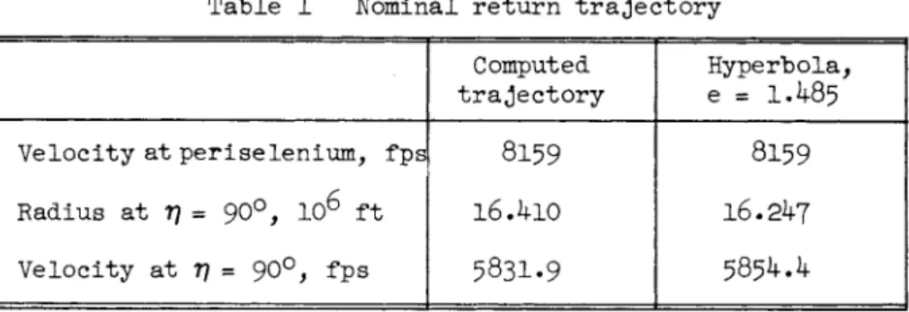
A nominal return trajectory (shown in Table l) was computed on an IBM 704 using a program that includes the Earth, moon, and sun gravitational fields, EarthTs oblateness, and lunar orbit eccentricity. This trajectory has an initial altitude of 123-7 naut miles above the lunar surface, transit time of 77·6 hr, and a vacuum perigee radius of 3264 naut miles. An hyper- bola with eccentricity e = 1.485, approximating the nominal return trajectory in the vicinity of the moon, is shown in Fig.
2. The small differences between the computed trajectory and the hyperbolic approximation are shown in Table 1.
Transfer From Circular Parking Orbit
The assumed geometry of direct abort is shown in Fig. 3· A two-impulse maneuver applies velocity increments ( Δ ν ) at points 1 and 2, transferring the spacecraft from the parking orbit to the nominal return trajectory. The transfer ellipse is con-
strained tangent to the return trajectory at point 2. Thus, the first impulse puts the vehicle on the transfer ellipse, and the second adds velocity as required to match the return
trajectory.
Defining the angles in the figure, the problem can be stated as follows: Given: r-j_, r 2 , V±> V 2> orbital elements ( Δ νχ, Δ ν2, ) of transfer ellipse.
For each departure point 771 there are an infinite number of possible insertion points Ύ]2. However, to limit r2 to within 3 lunar diameters (as mentioned previously), 7J2 should be less than 1 1 1 deg. Moreover, TJ2 cannot be less than TJ]_; hence
\ * V2 *111 deg.
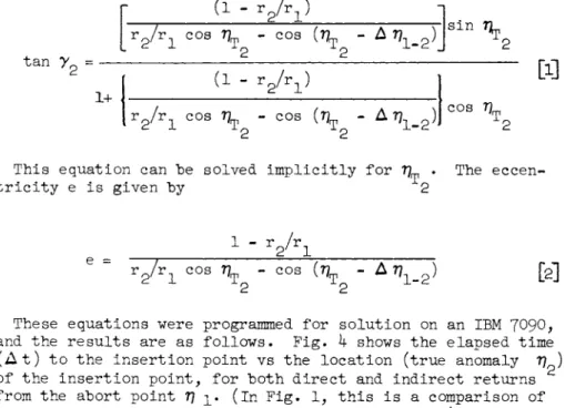
Equating the parameter ρ (semi-latus rectum) of the transfer ellipse at points 1 and 2, and substituting for eccentricity e in terms of the known flight path angle, at point 2 yields the following equation:
453
tan
r
2=
1+
(1 - rg/ri) •
R2/ / rlC 0 S \ ' 0 0 3 " Δ \-2*
î1 - r 2/ri ) î
sin
r2/r i cos - cos ( τ ^ - Δ τ ^ ) C O S 77
[ι]
This equation can he solved implicitly for 7]^ . The eccen-
tricity e is given by 2
e =
1 - ν2/ν±
r 2/ri c o s \ -c o s (Uj, - Δ\ _ £ These equations were
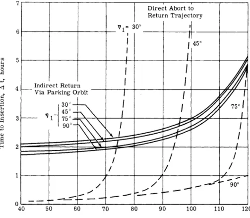
and the results are as ( A t ) to the insertion of the insertion point, from the abort point Tj transit times on paths T?2 region of interest, each abort location TJi long to reach point P 2
V
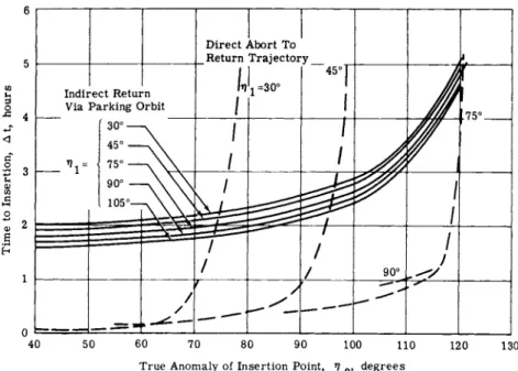
programmed for solution on an IBM 7090, follows. Fig. k shows the elapsed time point vs the location (true anomaly
for both direct and indirect returns ]_. (in Fig. 1 , this is a comparison of
C P 2 and C A P 2 , respectively.) Within the a break-even point is seen to exist for at which the direct abort takes just as as the indirect abort.
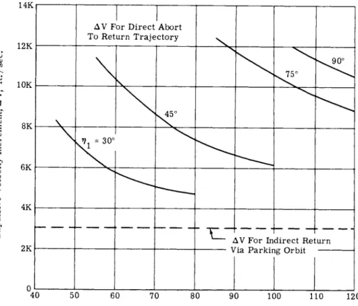
Fig. 5 gives the corresponding impulsive velocity require- ments for the two-impulse direct return and the single-impulse
indirect return. A cross-plot of these results (time saved by direct return vs the associated Δ V penalty) for various abort locations is shown in Fig. 6. The sharp knees represent regions of minimum Δ V penalty because further increases in Δ ν produce only slight increases in time saved, whereas small decreases in Δ V significantly reduce the time saved. Hence, a best operating envelope, such as shown in Fig. 6, can be drawn connecting these regions, to uniquely define the potentialities of this mode of direct abort for each initial abort location.
The resulting values are shown in Table 2 . Transfer From Elliptical Parking Orbit
Similar results for direct aborts from the elliptical parking orbit are presented in Fig. 7-9· As expected, direct abort from the elliptical orbit requires slightly more Δ ν from a given location than the circular orbit. The best operating points are shown in Table 3.
In general, it appears that the two-impulse direct returns are of questionable usefulness. The time savings are relative- ly small (less than 3 hr compared with 77 hr moon-to-Earth transit time) regardless of the velocity increment applied.
Δ V is not particularly limited, because if the mission is aborted while still in the parking orbit, over 12,000 fps nor- mally used for landing and take-off are available. It may be that more time could be saved in returning to Earth by perform- ing an indirect return and then using the available Δ V to accelerate the moon-Earth return trajectory. This possibility requires further consideration.
INDIRECT-RETURN ABORTS Return from Parking Orbits
Indirect return from the parking orbit can be handled readily by remaining in the orbit to point A (Fig. l) and performing a one-impulse transfer to the return trajectory at that point.
Required Δ ν and elapsed At for such cases are shown in Figs.
k, 5> Ί> and 8. Two-impulse transfers are employed if it becomes necessary to change the periselenium altitude or orienta- tion of the return trajectory, to account for variations with time in the moon's position relative to Earth .and sun. Indirect return can be made from any location 7J^ on the parking orbit.
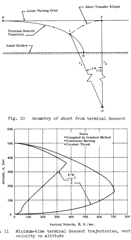
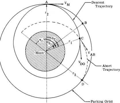
Abort From Terminal Descent
The terminal abort trajectory is indicated as segment FH in Fig. 1, and the geometry considered is shown in Fig. 1 0 . The abort begins at an arbitrary point 1, with an initial impulse that places the vehicle on a transfer ellipse whose aposelenium occurs at point 2, tangent to the original parking orbit. In this case, the terminal descent and subsequent abort return was from the 50,000-ft periselenium of the elliptical parking orbit.
Nominal descent trajectory
The selection of a nominal descent trajectory requires that many factors be balanced, such as propulsion, guidance and control system performance, abort capability, and error sensi- tivity. No attempt is made herein to select a best nominal descent trajectory based on these factors, but by examining available trajectories some insight is gained into the abort considerations influencing descent trajectory shaping.
A number of descent trajectories were available in which either elapsed time or propellant consumption (or both) was minimized by applying the gradient, or steepest descent,
455
method of variational calculus (2). The required thrust-angle program was determined for optimum trajectories for both con- stant thrust/weight ratio and constant thrust and for continuous and intermittent burning. Two representative continuous
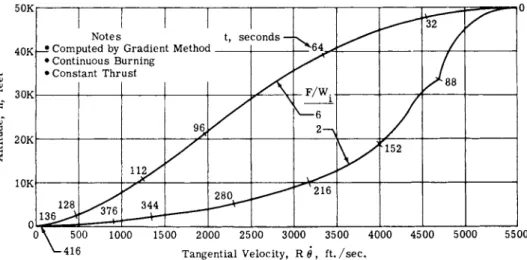
burning, constant-thrust trajectories are shown in Figs. 1 1 - 1 3 · As shown, these are not usable trajectories because the
tangential velocity component should be reduced to zero at least a few thousand feet above the surface, and the thrust-angle program must be simplified to permit mechanization in a real system. However, these modifications could be made without changing the essential shape of the trajectories.
Basically, these are low flight-path-angle trajectories that retain high tangential velocity down to low altitude. This feature is desirable for abort, because it minimizes the Δ V required for abort from a given altitude. Thus, the vehicle could descend quite close to the surface, permitting a closer view without committing all the available Δ V in the event of abort. However, the high tangential velocity increases the error sensitivity of the range to touchdown, introduces terrain clearance reaction-time problems, and may eliminate the pos- sibility of obtaining closer reconnaissance at the lower altitudes.
These trajectories are also very economical of propellant, requiring within 1$ of the ideal minimum impulsive Δ ν . As constant velocity vertical descent or hover time is added, however, propellant consumption will increase by about lfo for every 20 sec.
Comparing the trajectories with initial thrust-to-weight ratios (F/Wi) of 2 and 6 (Figs. 11 and 12), the former is seen to be an extremely shallow-angle approach, accentuating the conditions discussed previously. However, it also offers lower vertical velocity and longer elapsed time than the higher thrust trajectory, which is desirable to allow more time for crew participation during piloted landings. Both trajectories offer the same low propellant consumption. But because the F/W-j_ = 2 trajectory favors the above-mentioned abort considerations to a greater extent, it is used as a nominal terminal descent on which abort requirements are subsequently based. These abort requirements are therefore close to the minimum attainable and will undoubtedly increase as the nominal trajectory is reshaped to reduce its touchdown-error sensitivity and to simplify its thrust-angle program.
456
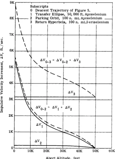
Impulsive abort trajectories
Using the (F/ WJ _ ) =
2
terminal descent trajectory as the point of departure, two-impulse transfer ellipses were computed assuming inpulsive thrusting. In addition to the tangency constraint already discussed, the transfers were limited to an increment in true anomaly (Δ 7?i-2) of 15 deg. This limit is considered necessary to provide a relatively rapid ascent with adequate terrain clearance. Downrange distance covered during the ascent is 215 naut miles, which is consistent with the distance covered during descent. Such a constraint on Δ V±-2 will increase the Δ V requirement about 10/o above that required for a Hohmann transfer (Δ T?i_2 = ^ 0 d e g ) . Hence, for the transfer ellipse, r^_, rg, ?7i, V2 a n (^ ^2 a re known, and the orbital elements can be determined directly. The resulting Δ V requirements are given as a function of abort altitude in Fig. Ik. Abort Δ V is minimal down to low altitudes because of the shape of the descent trajectory.Direct Rendezvous in Parking Orbit - Indirect Return to Earth This case is represented by path DEAP in Fig. 1. A lunar landing vehicle, initially at point D, aborts and rendezvous with a mother vehicle, initially at DT. Rendezvous is com- pleted at E, and the combined vehicle then proceeds on an indirect return to Earth via path AP.
Whether or not this maneuver is feasible can be determined by investigating the overall trajectory characteristics, in terms of the velocity impulse and guidance accuracy requirements. A discussion of the mathematical model and the resulting abort trajectory requirements follows.
Velocity requirements
The effect of orbital perturbations in causing out-of-plane motion between the landing craft and the mother vehicle is small because of the short time of flight during the descent phase of the lunar landing mission. Therefore, the gravitational forces can be assumed to follow the inverse-square law, and the
orbital transfers can be considered to be coplanar transfers.
The geometry is shown in Fig. 1 5 · The mother vehiclefs orbit is assumed to be the previously considered 100-naut mile
circular parking orbit. It is also assumed that the abort transfers are achieved by impulsive velocity corrections.
457
The transfer (abort) trajectory from the descent orbit back to the mother vehicle is not arbitrary because two constraints were imposed:
1 The two vehicles must arrive at the same point in space at the same time (time constraint).
2 The rendezvous must take place at the aposelenium of the abort trajectory. This will generally yield the minimum Δ ν requirement for direct rendezvous, i.e., less than l80 deg central angle Δ Tj. (See Ref. 3 for typical results of this type.)
To determine the abort trajectory that meets the above constraints, it was necessary to equate the time for the aborted vehicle to travel CD to the time it takes the mother vehicle to traverse BD. Thus, t = tp r (, where
CD'
3/2
"BD = — Ι 7 Γ + *i - *c - V
„
1/2"CD
2
tan1-e
A B
1+e AB
tan -
"eA B y ï ^ A B
However, the unknown is the true anomaly of the abort point 7?c, and, as a result, the abort trajectory had to be determined by trial and error. .The necessary iteration to determine the true anomaly was performed by the IBM 7090 digital computer.
Once T]c was found, all the properties of the abort trajectory (velocity impulse, error coefficient, etc.) could be determined.
The abort trajectoryTs orbital elements, the time of transfer and the velocity impulse requirements that meet the afore- mentioned constraints are shown as a function of the anomaly of the abort point T\ in Fig. l 6 . In the case of abort shortly after separation from the mother vehicle, the time to
rendezvous can "be reduced greatly at a small Δ V penalty
"by waiving the requirement for tangential intercept.
GUIDANCE PERFORMANCE REQUIREMENTS
The guidance performance requirements for a direct abort can be related to error coefficients for the parking orbit and transfer trajectories. In this way, errors at the final point
(i.e., the point of rendezvous) can be determined in terms of errors made at the initial point. Because the mother, descent, and abort orbits are analytic and the deviations from the nominal trajectory are small, it is possible to assume small perturbations. Thus, only linear terms of the Taylor series expansion are retained, making it possible to derive exact expressions for these error coefficients. Error coefficients, showing the effect of injection errors for the descent and abort trajectories were derived and are presented here:
Descent Trajectory
ôr.
(l - e) cos Τ]^
1 - e cos 77
(1 - e) . _ôe_
1 <- e cos 77^ 9 dr^
de
7 2 ôr.
(l *- e cos 7]^).
r2 r V 2 M - μ
ν
M2 μ e
Or 3V, M
oe M
(l - e) cos 77 L 1 - e cos 77
r2VM " μ
v
2 M M2 e
r
àv
2 M(1 - e cos 77^)
àr = 0
459
Abort Trajectory or.
"AB
(1 + em cos T ?c)
M2e AB
o r . AB
2 2
* 1 A BV C°3 YA B
" Sb -(ELA B}
C O S T) 4- C Γ
1
ay
ABV
A I
rl2 C 0S RA B S LN YA BEA B}
cos 77 + c
riJ
(2μ -V a b Pl)
These error coefficients are presented as functions of true anomaly of the abort point 7?^ in Fig. 1 7 · The abort trajectory becomes considerably less sensitive to initial errors if the
injection point is for 77^ > 60 deg, which is a favorable factor for accomplishing the rendezvous in this region, despite the increased Δ V requirement compared with that at lower values of 7]]_. However, as the velocity is increased the tolerance to errors in time (or 7J^) becomes critical.
Indirect Rendezvous From Elliptical Parking Orbit
In addition to the direct rendezvous previously described, a variety of indirect paths can be followed which require greater time to rendezvous but less Δ ν . An extreme example for the
nominal parking o r b i t s considered i s a single-impulse maneuver in which the landing v e h i c l e i s allowed t o remain in the inner o r b i t u n t i l i t coincides with the mother v e h i c l e at point A in F i g . 1 a f t e r 14 o r b i t s , or approximately 28 hr. This time can be reduced t o l e s s than 4 hr by two-impulse maneuver in which the lander, on i t s f i r s t pass through point A, i s i n s e r t e d i n t o an e l l i p s e of higher energy than the mother-ship parking o r b i t so that i t s p o s i t i o n coincides with the mother ship the
second time i t reaches A .
A further time reduction t o about 2 hr can be obtained by the three-impulse maneuver i l l u s t r a t e d in F i g . l 8 . Here, the lander i s placed immediately on an e l l i p s e AB, which i s changed by an impulse at point Β t o a new e l l i p s e BC, which i n t e r c e p t s the mother v e h i c l e at point C. The impulsive v e l o c i t y increment required t o perform t h i s maneuver i s shown as a function of abort p o s i t i o n in Figo 1 9 . Time and Δ V f o r the various abort with rendezvous modes are l i s t e d in Table 4o
Another approach that has been considered i s t o descend from the c i r c u l a r o r b i t t o 50,000 f t ( s t a r t of powered descent) v i a an e l l i p t i c a l o r b i t that has a p e r i o d equal t o the period of the c i r c u l a r o r b i t and has a periselenium of 50,000 f t . The t o t a l Δ V required t o i n j e c t i n t o t h i s e l l i p t i c o r b i t from a 100 naut mile c i r c u l a r o r b i t i s approximately 460 f p s . The advantage of t h i s "synchronous o r b i t " approach i s t h a t , i f an abort i s required p r i o r t o s t a r t of terminal descent, the v e h i c l e can continue along the e l l i p t i c path t o the i n j e c t i o n point and achieve rendezvous by applying an a d d i t i o n a l 460ft/
sec Δ ν . Maximum time f o r rendezvous would be equal t o the p e r i o d o f o r b i t , or 126 minutes.
Direct Rendezvous From Lunar Surface - I n d i r e c t Return t o Earth In t h i s case, a landing v e h i c l e i s launched from the surface of the moon and rendezvous with the mother v e h i c l e in a known o r b i t . Launch occurs from a point outside of the plane of the mother o r b i t . The mother v e h i c l e i s assumed t o be in a 100- mile c i r c u l a r o r b i t i n c l i n e d 10 deg t o the lunar equator. The
lander v e h i c l e i s launched from the equator at points 13 deg and 26 deg from the descending node l i n e , corresponding t o 24- and 48-hr stay t i m e s , r e s p e c t i v e l y .
F i g . 20 shows the geometry of the s i t u a t i o n . Results ob- tained from the i n v e s t i g a t i o n s are shown in F i g . 21· T o t a l v e l o c i t y increment i s p l o t t e d as a function of downrange angle of i n t e r c e p t f o r two-impulse t a n g e n t i a l t r a n s f e r t r a j e c t o r i e s . The second impulse i s applied at the t a n g e n t i a l i n t e r c e p t point t o match the v e l o c i t y and heading angle of the two
4 6 1
vehicles. The initial heading angle at launch (shown on Fig. 2l) determines the downrange angle at intercept and the angle at which the lander vehicle intersects the plane of the vehicle in orbit. From such curves, launch windows can be determined for each value of Δ V provided in the lander vehicle.
For example, for a 48-hr dwell time on the moon, the min- imum Δ V required is approximately 5950 fps and corresponds to a downrange intercept angle of 50 deg. The heading angle required at launch to produce this condition is approximately I O 2 . 5 deg. However, if after the same dwell time on the moon the ferry vehicle had available a total velocity impulse of 625Ο fps, then the permissible downrange angle of intercept would extend to a range between 23 deg and l40 deg, with the corresponding heading angles at launch varying between 111 deg and $k deg respectively. This yields a launch-time win- dow of 22 min.
The geometry of the nominal moon-to-Earth trajectory of Fig.
2 differs from that shown in Fig. 20 in that the inclination im is higher, as shown in Fig. 22. Hence, the Δ V required to rendezvous with a parking orbit in this plane would be some- what higher than is shown in Fig. 21 for an equatorial launch
site, due to the increased heading-angle change required at intercept.
CONCLUSIONS
1 In the preliminary planning of manned lunar-mission pro- files, abort considerations can significantly influence tra- jectory selection and operations sequencing.
2 In certain instances, simple approximations to the flight mechanics can be used in determining required abort velocity increments and time-to-return. Coplanar central force-fieId equations can be used in most abort situations near the moon.
However, the validity of approximating direct aborts by a series of elliptical transfers to a nominal moon-to-Earth return trajectory requires further study.
3 Direct abort and return to Earth by transferring to a nominal return trajectory appear of very limited value because return-time saved is low and velocity requirements are high.
k In selecting a nominal terminal descent trajectory for a manned mission, abort considerations and fuel economy favor shallow-angle descents. This must be balanced against error
462
sensitivity, crew participation in landing, and terrain clear- ance requirements, which tend to favor steep descents.
5 Indirect returns, involving abort and direct or indirect rendezvous, can be accomplished in a number of ways. Indirect rendezvous takes up to l-l/2 hrs longer than direct rendezvous but requires much less velocity increment.
ACKNOWLEDGMENTS
The authors wish to acknowledge the contributions of the fol- lowing persons: Alfred Nichtenhauser, who computed the opti- mized terminal descent trajectories; Charles Giannetto, who computed the moon-to-Earth return trajectory; and Samuel S.
Koeppel, who edited the technical content and prepared the paper for publication.
REFERENCES
1 Kelly, T.J. and Adornato, R., "Determination of abort way-stations on a nominal circumlunar trajectory," ARS Pre- print 2085-61 (October 1 9 6 1 ) .
2 Kelley, H.J., "Method of gradients," Optimization Tech- niques, edited by George Leitman (Academic Press, New York, 1 9 6 1 ) , Chap. 6.
3 Eggleston, J.M., "A study of the optimum velocity change to intercept and rendezvous," NASA TN D 1029 (February 1962).
Table 1 Nominal return trajectory Computed
trajectory
Hyperbola,
e = Ι Λ 8 5
Velocity at periselenium, fps
8159 8159
Radius at 7? = 90°, 1 06 ft
16.410 16.247
Velocity at 77 = 90°, fps
5831.9 5854Λ
463
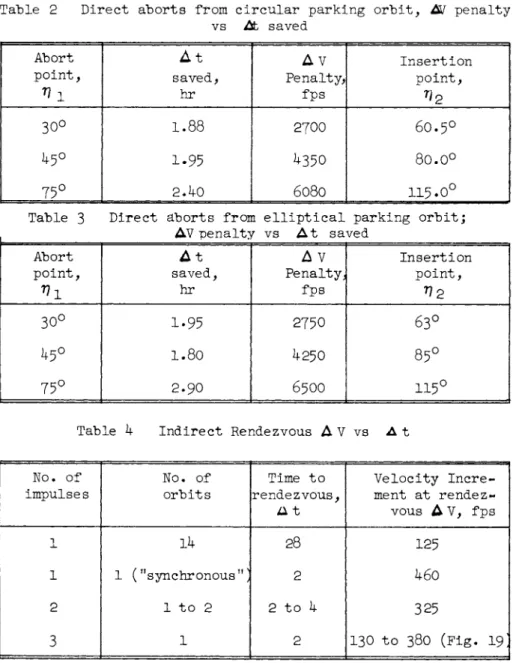
Table 2 Direct aborts from c i r c u l a r parking o r b i t , A / penalty vs At saved
Abort p o i n t ,
1
A t saved,
hr
A V Penalty,
fps
I n s e r t i o n p o i n t ,
30° 1.88 2 7 Ο Ο 6 0 . 5 °
1-95 ^350 8 0 . 00
75° 2.k0 6 0 8 O 1 1 5 · 0 °
Table 3 D i r e c t aborts from e l l i p t i c a l parking o r b i t j AV penalty vs A t saved
Abort p o i n t ,
A t saved,
hr
Δ V Penalty}
fps
I n s e r t i o n p o i n t ,
^ 2
30° 1-95 2750 63°
1.80 425Ο 85°
75° 2.90 65ΟΟ 1 1 5 °
Table k I n d i r e c t Rendezvous Δ V vs A t
No. of impulses
No. of o r b i t s
Time t o rendezvous,
a t
V e l o c i t y I n c r e - ment at rendez- vous Δ V, fps
1 Ik 28 125
1 1 ( "synchronous"] 2 460
2 1 t o 2 2 t o k 325
3 1 2 130 t o 3 8 Ο ( F i g . 1 9 ;
465
A To Earth DEPICTED TRAJECTORIES Nominal Abort OA = Earth - Moon Transfer Direct Returns ΑΡχΡ2 = Moon - Earth Return ΒΡχ = From Elliptical Parking Orbit ACG = Circular Parking Orbit CP2 = From Circular Parking Orbit AB F = Elliptical Parking Orbit FH = Terminal Descent Indirect Returns HI = Lunar Ascent BAP = From Elliptical Parking Orbit CAP = From Circular Parking Orbit FLAP = From Terminal Descent DEAP = Rendezvous from Elliptical Parking Orbit FGAP = Rendezvous from Terminal Descent Fig. 1 Abort situations considered
Hyper (e=1.4
bola ν 853) \
• r
/ S /
//
//
/ / /
//
/Ä
V -A c
Mc
tual 4-Body
>on to Earth icuum Per ig
Trajectory 'ee = 3758 ir
//
//
//
(V:
tual 4-Body
>on to Earth icuum Per ig
Trajectory 'ee = 3758 ir ά.)
y
To Ear th • 2K 4K 6K 8K 10K 12K
Distance, statute miles
F i g . 2 M o o n - t o - E a r t h t r a j e c t o r y
OP = Major Axis of Parking Orbit and Return Trajectory OF Major Axis of Transfer Ellipse VELOCITY DIAGRAM r- Direct Return Ρ ρ \ Transfer Ellipse \ Nominal Moon - Earth Λ Lunar Parking Orbit Return Trajectory \ Fig. 3 Direct abort geometry
467
40 50 60 70 80 90 100 110 120 True Anomaly of Insertion Point, η ^ degrees
Fig. k Elapsed time for direct and indirect returns from 100-naut mile circular parking orbit
True Anomaly of Insertion Point, η ^, degrees
Fig. 5 Velocity increment for direct and indirect returns from 100-naut mile circular parking orbit
469
4o0| 1 1 1 1 1 1 1 1 1 1 3 5 |__\_
/ \
w Operating Envelope \ 900δ
3·° 1 ι— / Ν
3 / \ e 2. 5 -7—V
I 20 _^~ίτ— — j ^^^^^^ —S / / I
1.5j j
aI I
öI i
§ '?=30°/ 45°/ 75° H 1.0 f * 0I 1 U 1— I 1 1 U 1 1 1
0 IK 2K 3K 4K 5K 6K 7K 8K 9K 10K Velocity Increment Penalty, Δ V, ft./sec. Fig. 6 Time saved vs velocity increment penalty for direct return abort from 100-naut mile circular parking orbit40 50 60 70 80 90 100 110 120 True Anomaly of Insertion Point, V ^> degrees
Fig. 7 Elapsed time for direct and indirect returns from elliptical parking orbit
14K
True Anomaly of Insertion Point, η 2, degrees
Fig. 8 Velocity increment for direct and indirect returns from elliptical parking orbit
471
3. 5j 1 1 1 J 1 1 1 1 1 3. Ο /
I /{ \
ο 2.5 1 7 V Α Operating / \ á Envelope \^ & 2.0 ^ àΓ ι -Τ^-Τ —
& νË=30°Ι 45°/ 75°I .. . ^— ^ \ ο' 1 1 1 —I — I 1 L I 1 1 1
0 1Κ 2Κ 3Κ 4Κ 5Κ 6Κ 7Κ 8Κ 9Κ 10Κ Velocity Increment Penalty,Δ V, for Direct Return, ft./sec. Fig. 9 Velocity increment vs time saved for direct abort from elliptical parking orbit KELLY, ADORNATO, AND SPEISERο
Fig- 10 Geometry of abort from terminal descent
60K
50K
40K
<
20K
10K
1 1 1
Notes
•Computed by Gradient Method
•Continuous Burning
•Cor istant Thr ust
W.
1 2
\
0 100 200 300 400 500 600 700 800 Vertical Velocity, R, f t . / s e c .
11 Minimum-time terminal descent trajectories, vertical velocity vs altitude
473
5 0 K
| — ι — ι — ι — ι — I — I — I IHsr-pT
Notes t, s e c o n d s — \ ^y^* / 40K — Computed by Gradient Method 1 _ 64^. ^ _ /
• Continuous Burning É
~ · Constant Thrust s J
- 30K ^ S J- F / W . yC
I 20K — ^ V ~^^>
1 1 2 /
10K y^- —:^vr;
S
280 2 16 128 ^<Tf i 344 ^o'
ν ' —1 1 1 1 1 1 1 1 1 1θ \ 500 1000 1500 2000 2500 3000 3500 4000 4500 5000 5500
^-416 Tangential Velocity, R 0 , f t . / s e c .
Fig. 12 Minimum time terminal descent trajectories, tangential velocity vs altitude
30r -6pi 1 1 1 1
I Notes
• Constant Burning / \ 5 I · Constant Thrust ÷ ' \ F
20 - -5 - L · F/W. = 2 γ -
Ι
1Γ \
δ
ί ο -s?
- 4 Jy
ι \% ι / \ \
k * / . ^
6 0 αΓ Ι / I \
0 - hi -3 —I / - - - - \
" < ι / I \
1- 1 0 - 5 - 2 - 1
-/-
V —£ I \
.2 - . ! J0 1
^ \
-30
L
ο'1 1 1 1
0 IOK 20K 30K 40K 50K
Altitude, feet
Fig. 13 Terminal descent trajectory, thrust and flight*-path angle vs altitude
9K
8K
7K
« 6K
5K
4K
3K
2K
IK
\
1 —
\
\
τ Subscript 0 Descer 1 Transf 2 Parkin 3 Return τ
S
it Traject er Ellipse g Orbit, ί Hyperbol
τ
•ry of Fi£
Î, 50,000 LOO n. mi a, 100 n.
ι jure 5.
ft. Aposel . Aposelen mi.Peris
enium ium elenium
\
\\
\\
\ V Δο ν-3 = A VC u2 + ΔΥ 3
\\ \\ \\
s.
V \\ \\
\^ Δ ν0 - 2
\ \
= Δ νχ +
\x
Δ Υ2
10K 20K 30K 40K Abort Altitude, feet
5 OK bOK
Fig. lk Abort from terminal descent, velocity increment vs abort altitude
475
A = Point of Injection
Β = Position of Mother Vehicle at Time of Abort C = Abort Point
D = Rendezvous Point
Fig. 15 Coordinate system used in direct rendezvous abort analysis
477
Orbit Characteristics Circular (Mother) Descent R = 1038 n. mi. R. = 1038 n. mi. A e = 0. 0463 1 1 1 1 1 |6K
i I
% 160r + 5K g ^ / Velocity a Av. Impulse ·« I 3 ' ι Total ß Η Φ 120- 4Kr g 0.8j
q7
4K §-'•si x Λ -7 /n
2nd« « I
80- S 3K-g
0.6V - —^ - / //
3K „3 ! ~ o r
1ν / v / y / ;
fig 40- ? 2K- ^ 0.4 \-y / / /2K *
ε
ce / \^ /y / ^
g*o
L οικ -
w 0.2 * y^^^X 1K ^g
u f ° 0L I
0h
^\^^\1 1 1 1
0 > Δ 0 40 80 120 160 200 True Anomaly Measured from Aposelenium, degrees Fig. l6 Abort trajectory characteristics for direct rendezvous6K
4K
T3 c ο
2K
Α. Error in de-orbit initial conditions on descent trajectory.
i
br
I
— •
b rD
i
3.0
2.0
H 1.0
Β. Error in abort trajectory initial conditions on rendezvous point.
6K
4K
•α 2K
True Anomaly from Aposelenium, η^, degrees
Fig. 17 Error coefficients for direct rendezvous abort
Ο
To Earth
OA = Travel Along Descent Orbit
A = Point of Vehicle Abort, 1st Impulse Applied A B = One-Half of 1st Transfer Orbit
Β = Apolune of 1st Transfer Orbit, 2nd Impulse Applied BC = One-Half of 2nd Transfer Orbit
C = Rendezvous Point on Circular Orbit, 3rd Impulse Applied
Fig. 18 Three-impulse indirect rendezvous
0 40 80 120 160 200 240 280 320 360 Vehicle Position Along Its Orbit, degrees (Measured from Aposelenium)
Fig. 19 Impulse required for three-impulse indirect abort rendezvous (rendezvous time, 130 min)
479
/ / — G r o u n d Track \ / / of Rendezvous Orbit \
^S s^C<£>> \ A—Launch Pts.
\ \ y / \ \
\ ^^^^^^^ É
Fig. 2 0 Geometry of launch from lunar surface
φ CO 140r >8Κ| 1 1 1 1 1 1 1 1 1
I © ,30 ' 1 tfef e ^ ο Ι. Α—-¹ ι J v_y^>-L/ £ 120- g
7K ~" 1 I
j HO- S \^ N N ^y/ ι ι
' Γ·8™ ' — ~ ~ ~ ^ "^ît^^ - ^ j^ )
ffi S AV Req'd for Launch ^N 90- £ Heading Angle at Launch 1 χ \ £ (Τ) From Launch Pt. 1 \ \ (2) From Launch Pt. 2 ^ 80L >
5κΙ 1 1 1 1 1 1 1 1 1 a 0 20 40 60 80 100 120 140 160 180 Η Down-Range Angle of Rendezvous, 0, degrees Fig. 21 Requirements for direct launch and rendezvous
481
(Viewed Looking Toward Earth)
Fig. 22 Geometry of nominal moon-to-Earth trajectory