TRAJECTORY CONSIDERATIONS FOR THE RETURN TO EARTH PHASE OF LUNAR MISSIONS J. P. Gapcynski1 and R. H. Tolson1
NASA Langley Research Center, Langley Station, Hampton, Va.
ABSTRACT
This paper presents a discussion of the lunar injection con- ditions that are required to establish Earth-return trajecto- ries satisfying specified re-entry conditions. It has been assumed in this analysis that the return trajectory is initi- ated either from a circular lunar orbit having an arbitrary inclination and nodal position with respect to the Earth-moon plane or from an arbitrary position on the lunar surface. In the latter case, it is further assumed that a lunar parking orbit is established prior to injection. No consideration is given to the use of orbital plane changes to insure proper Earth re-entry.
INTRODUCTION
The return flight from the moon is one of the most important phases of the overall manned lunar mission, since the restric- tions imposed by the return requirements may well dictate the entire mission profile and timetable. The problem of defining these requirements involves the determination of those lunar injection conditions that result in trajectories satisfying specified Earth re-entry conditions. For the analysis to be complete, consideration must be given to initiation of the return flight both from the lunar surface and from any arbi- trary low-altitude lunar orbit.
This paper will present the results of an analysis of the lunar return mission based on a patched-conic type of solution.
Consideration is first given to an overall discussion of the physical aspects of the return mission, and this discussion is then augmented with results of a more quantitative nature.
Presented at the ARS Lunar Missions Meeting, Cleveland, Ohio, July 1 7 - 1 9 , 1962.
lAerospace Engineer.
J . P. GAPCYNSKI A N D R. H. TOLSON
METHOD OF ANALYSIS
It is difficult to choose a method of attack on the lunar return problem because of the seemingly endless number of vari- ables that are involved. Of basic importance in the applica- tion of any method, however, are the constraining relationships that each return trajectory must satisfy at Earth re-entry. In addition to the designation of the re-entry angle and altitude, it is usually required to specify the location of the touchdown point on Earth1s surface. The longitude of the touchdown point will be determined by the time selected for injection and the return trajectory flight time. The latitude of the touchdown point, for a given re-entry range and lunar declination at the time of injection, is a function of the inclination of the return trajectory to the Earth-moon plane ( l ) . ^ Because of the change in the moon1s declination, the return inclination that is required for a specific touchdown latitude will vary
throughout the month, and, thus, it becomes necessary to inves- tigate the return problem for a range of values of the return trajectory inclination to the Earth-moon plane. This inclina- tion, then, becomes one of the independent parameters of the problem.
With regard to the designation of the required return perigee distance, it was assumed in this analysis that the specifica- tion of a constant value of the angular momentum of the return trajectory was equivalent to the specification of a constant return perigee radius. This relationship is exact for trajec- tories that have parabolic energy and is nearly so for the energy levels dealt with here. As an indication of the valid- ity of this assumption, it is to be noted that the variation in the computed perigee radius was of the order of 30 miles for the range of energy levels of interest in this investigation.
Changes that were made in the assigned value of the angular momentum to eliminate this variation had a negligible effect on the return injection conditions.
To determine the required lunar injection conditions, it may be assumed, without loss of generality, that injection will occur at an altitude of 50 miles with an injection angle of 0°.
Thus, the problem of achieving a satisfactory Earth return becomes one of determining the permissible values of the remaining injection conditions. Appropriate parameters are the velocity, the lunar orbit inclination and nodal position, and the angular position of the injection point in this orbit.
^Numbers in parentheses indicate Reference at end of paper.
For the parametric study presented in this paper, a combina- tion of two-body solutions, or the patched-conic type of anal- ysis, was used. The trajectory characteristics at the lunar sphere of influence were determined so as to satisfy the required Earth re-entry conditions, that is, the specified
value of the angular momentum h and the return inclination I.
The lunar injection conditions were then adjusted so as to match these requirements.
The trajectory requirements at the lunar sphere of influence may be determined from the following two equations, when the angular momentum h and the return trajectory inclination I are specified:
hz - h cos I = 0 [l]
hx 2 + hy2 - h2s i n2I = 0 [e]
where hx = R vm sin i sin ω + Rvs± s in ßs i n * sî-n ^
hy = mvsi sin i sin(œ + β) - R vsi sin β sin i cos Ω hz = m vm + Rvs± sin β cos i - Rvm(cos ω cos Ω
- cos i sin Ω sin ω ) - mvsj_Qin Ω COS(Ü) + β)
+ cos Ω COS i sin(ü) + ß)j
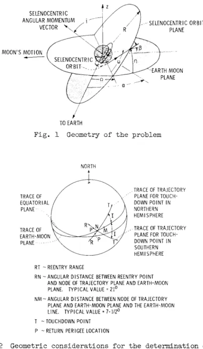
and where the parameters are defined in the symbol section and shown in Fig. 1.
The origin of coordinates is centered at Earth, with the neg- ative x-axis directed toward the moon, the x-y plane is in the Earth-moon plane, and the ζ-axis is perpendicular to the Earth- moon plane in a northerly direction.
Eqs. 1 and 2 were solved for the values of the vehicle veloc- ity with respect to the moon vsj_ and the angular position ω of the vehicle at the time it exits from the moon's sphere of influence, by a Newton-Raphson technique, with assigned values of the lunar orbit inclination i and nodal position Ω. It is to be noted that the angle β between the velocity vector and the radius vector, at the sphere of influence, is a func- tion of vsj_ and, therefore, must itself be determined by an iteration technique.
J. P. GAPCYNSKI A N D R. H. TOLSON
VARIATION OF THE RETURN TRAJECTORY INCLINATION
In view of the importance of the inclination of the return trajectory to the Earth-moon plane in obtaining the desired touchdown latitude, and in the discussion of the results which follows, it is desirable to examine the variation of this parameter in more detail. The latitude of the touchdown point which may be achieved from the return flight is a function of the re-entry range, the inclination of the return trajectory to the Earth-moon plane, and the declination of the moon at the time of injection, or, in this case, at the time the vehicle leaves the sphere of influence.
The orientation of these parameters is shown in Fig. 2.
Point M is the intersection of the Earth-moon line (extended through Earth) with the surface of Earth at the time the vehi- cle leaves the moon!s sphere of influence. To an observer at M, the moon would be at the nadir. The intersection, on Earth, of the line of nodes of the return trajectory plane and the Earth-moon plane is at the point N. A representative value for the angular displacement between the Earth-moon line and this nodal line is 7-l/2° for trajectories that have energy levels of interest for the return mission. Re-entry occurs in the trajectory plane at the point R. A typical value for the angu- lar distance between the re-entry point R and the nodal line intersection point Ν is 2 1 ° . It should be noted that for touchdown points in the northern hemisphere (for latitudes greater than the maximum declination of the moon) the return trajectory plane must be oriented so that the ascending node of the trajectory is near the perigee location. For touchdown points in the southern hemisphere, the descending node of the return trajectory must be near the perigee point.
The variation of the associated parameters for touchdown latitudes of ±30° is shown in Fig. 3· The maximum lunar declination for these results is 28-l/2°, and the angular dis- placements between the re-entry point and nodal position, and the Earth-moon line and nodal position have the values men- tioned in the previous paragraph.
The ordinate in each case represents the inclination of the return trajectory to the Earth-moon plane, and the abscissa represents the angular position of the moon in Earth's equato- rial plane at the time the vehicle leaves the lunar sphere of influence. This position is measured from the moon's ascending node. The corresponding values of the inclination of the return trajectory plane to Earth's equatorial plane are given in Fig. k. From an examination of Fig. 3, it may be noted that the return flight which is initiated when the moon is near the
position of maximum positive declination (0 = 90°) requires large values of both re-entry range and inclination to the Earth-moon plane if the touchdown point is in the northern hemisphere. The reverse is true if the flight is initiated when the moon is near its position of maximum negative declina- tion (0 = 2700) or if an additional touchdown point is assigned which has a southern latitude.
In order to achieve increased return capability, from the time of month standpoint, it appears that both northern and
southern hemisphere locations are desirable for vehicle touch- down. This is especially true if the return flight is to be initiated from a lunar orbit having a low inclination to the Earth-moon plane. In this case, as will be shown later, it may not be possible to obtain return trajectories with high incli- nations unless a plane change is made. Therefore, unless both northern and southern touchdown latitudes are available, the return flight may be limited to a specific time interval during each month.
DISCUSSION OF RESULTS
Prior to a discussion of the quantitative results of this investigation, it is desirable to examine the physical aspects of the return mission. This may be readily accomplished if the assumption is made that the angle β between the velocity vector and the radius vector at the sphere of influence is zero.
Normally, this angle will be of the order of 3- l/2°.
Approximate Solution of the Angular Momentum Equations
The assumption that the angle β between the velocity vector and radius vector is zero means that the vehicle exit velocity vector is normal to the sphere of influence. With this assump- tion, the equations for the angular momentum components reduce to the following:
bx = R vm sin η hy = mvsj[ sin η
hz = m vm - R vm cos α cos η - m vsi cos η sin α where α and η are angular positions as shown in Fig. 1.
With these equations, the required exit position on the sphere of influence can be calculated explicitly as a function of the geocentric angular momentum and vehicle velocity. The results of this type of calculation are shown in Fig. 5 for four dif- ferent increments in injection velocity above the circular
J . P. GAPCYNSKI AND R. H. TOLSON
value for an altitude of 50 miles. Each curve represents the locus of exit points on the sphere of influence of those tra- jectories which have the desired re-entry characteristics and the specified injection velocity increment.
The minimum velocity increment to achieve Earth return under these assumptions is approximately
2580
fps, and the exit curve for this increment would he represented hy a single pointlocated in the Earth-moon plane at a longitude α of about 79°. The associated return trajectory would be in the Earth- moon plane, and the return flight time would be about 117 hr.
As the velocity increment is increased, the exit figure becomes somewhat elliptical in shape and increases in size. It should be pointed out that return trajectories with exit points off the Earth-moon plane have a nonzero inclination to the Earth- moon plane, and the maximum obtainable value of this inclina- tion increases as the velocity increases. For exit points with a positive latitude η, the descending node of the return tra- jectory is located near the return perigee point, and thus these positions are favorable for touchdown points in the southern hemisphere. For exit points with negative latitudes, the ascending node is located near the earth perigee point, and these positions are favorable for touchdown points in the northern hemisphere. It should also be pointed out with ref- erence to these curves that, for a given velocity, any trajec- tory that leaves the sphere of influence within the associated exit point curve will impact Earth.
When the velocity increment is such that a return inclination of greater than 90° is possible, the curves change shape and begin to neck down in the center portions. The regions of each
curve associated with trajectories that have a return inclina- tion of greater than 90° are represented by dashed lines in Fig. 5· Finally, with further increase in the velocity incre- ment, the locus of exit points splits into two distinct curves.
Additional increases in the velocity increment result in an increase in the separation distance and a decrease in the size of the two curves associated with each velocity. If the veloc- ity increment were to be increased without bound, the size of the exit areas would tend to zero at longitude values of 0°
and 180°. No acceptable exit areas exist beyond these values, that is, for longitudes between
l8o°
and360
0.
Note that, for trajectories that have exit points with longitude values between8o°
andl8o°,
the vehicle is heading away from Earth when it leaves the sphere of influence. Therefore, if the return trajectory energy is hyperbolic, a return flight is no longer possible even though the conditions on the inclination and angular momentum are satisfied.The results of this analysis may he reduced to a more work- able form by considering only those trajectories which have a return inclination, I, of less than 90°. In addition, since the independent parameter of interest is the inclination of the return trajectory to the Earth-moon plane, a more useful curve would be the locus of exit points on the sphere of influence of those trajectories that have a constant return inclination as well as the proper re-entry conditions. This type of variation, which may be obtained from the solution of Eqs. 1 and 2 for β = 0 ° , is shown in the lower portion of Fig. 6 for three values of the return inclination. The required velocity incre- ments and return flight times associated with each point are also given in Fig. 6. It should be noted that the minimum increment in velocity, above the circular value, increases with an increase in the specified return trajectory inclination.
From an examination of the results presented in Fig. 6, it is possible to determine the qualitative requirements for the return mission. For example, consider a selenocentric orbit that has an inclination to the Earth-moon plane of ΐ6θ° and an ascending node positioned at a longitude of 100°. (inclina- tions are designated as the angle between the positive ζ-axis and the angular momentum vector of the trajectory.) The inter- section of this lunar orbit plane is shown superimposed on the results presented in the lower portion of Fig. 6. The direc- tion of motion is indicated by the arrows. The intersection point of this plane with any of the constant return inclination
curves represents an exit point that satisfies both the inclina- tion and the re-entry conditions. The required injection velocity increment and the total flight time associated with this exit point are given by the curves in the upper portion of Fig. 6. If a return inclination of kO° is desired (assuming an exit point with a positive latitude), a velocity increment of approximately 2650 fps is required, and the resulting total flight time will be of the order of 1 1 2 hr. Selenocentric orbits with the same inclination but with nodal positions closer to the Earth-moon line, that is, with smaller values of longitude, would have lower return flight times and higher velocity increments associated with them. This is also true of orbits that have the same nodal position but with orbit inclinations greater than ΐ 6 θ ° . In general, it should be noted that for a successful return flight the values of the inclina- tion and nodal position of the selenocentric trajectory, at the time the vehicle leaves the sphere of influence, should be
such that the exit points occur for longitude values of less than 90°. The actual choice of position will involve a con- sideration of the required velocity increment, which increases as the longitude decreases, and the flight time, which decreases with a decrease in longitude.
J. P. GAPCYNSKI AND R. H. TOLSON
Exact Solution to the Angular Momentum Equations
Elimination of the assumption that the vehicle exits normal to the sphere of influence will displace the locus of accept- able exit points by approximately ±ß from the curves pre- sented in Figs. 5 and 6. This displacement is in the lunar orbital plane, and, therefore, the exact shape of the curves will depend on both the inclination and the nodal position of the selenocentric trajectory. Typical variations of the asso- ciated velocities and flight times are shown in Figs.
7
a a n < iTh
for representative lunar orbit inclinations. These results were obtained from the exact solution of Eqs. 1 and 2. The presentation of results in this form has been restricted to values of the return trajectory inclination to the Earth-moon plane I of 10° and 50°, and to return trajectories that have touchdown points in the northern hemisphere. The results are equally valid for touchdown points in the southern hemisphere if the position of the ascending node of the selenocentric trajectory is changed by
l8o°.
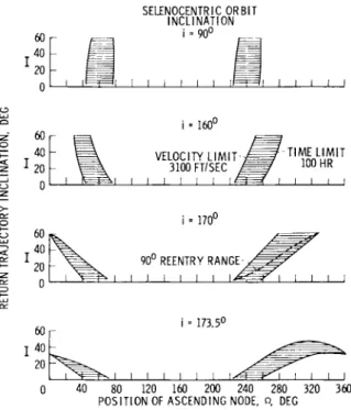
In order to obtain a composite of results of this type for several values of the return trajectory inclination, it was assumed that the maximum velocity increment allowed for the return mission (increment above the circular velocity at a 50-mile altitude) would be 3100 fps and that the maximum allow- able flight time would be set at 100 hr. These numbers were chosen arbitrarily, but it is felt that they represent practi- cal limitations of these quantities. The composite of results is presented in Fig. 8 for four values of the inclination of the selenocentric orbit to the Earth-moon plane within the range from
90°
tol8o°.
(Note that the direction of motion for inclinations within this range is such that the angular momen- tum vector of the selenocentric trajectory is directed below the Earth-moon plane.) Again, the results have been presented for trajectories with touchdown points in the northernhemisphere.
The shaded areas in Fig. 8 define the permissible variation in the position of the ascending node of the lunar orbit so as to achieve a satisfactory return flight over a range of values of the inclination of the return trajectory. The left boundary of each curve is defined by the magnitude of the maximum per- missible value of the injection velocity increment, and the right boundary is defined by the time limitation. An increase in the allowable value of either of these two parameters will increase the size of the shaded regions in this figure and thus broaden the permissible range in the lunar orbit nodal position. It is to be noted that, for selenocentric orbits with inclinations of the order of
I 7 3 . 5
0,
it is not possibleto obtain the higher values of return inclination with the pre- scribed velocity increment. For example, the minimum velocity increment to obtain a return inclination of 50° is approxi- mately 3200 fps for a lunar orbit inclination of 1 7 3 · 5 ° - It
should also be noted that, for values of the lunar orbit incli- nation of the order of 1 7 3 - 5 ° , there will be certain return inclinations for which the minimum possible velocity increment will have a return flight time of something less than 100 hr.
In the application of these results to the lunar return mis- sion, two possible injection situations may be anticipated:
1) that the return flight will be initiated from the lunar surface; and 2) that the return flight will be initiated from an arbitrary lunar orbit. In both cases, it is assumed, in this analysis, that injection takes place from a circular lunar orbit at an altitude of 50 miles. However, in the first situa- tion, some choice in the selection of this orbit is possible, whereas, in the second case the characteristics of the orbit may be dictated by other considerations, such as the use of a rendezvous technique.
If a coasting orbit is used in conjunction with the return flight from the lunar surface, it is possible to achieve a suc- cessful re-entry from any position on the lunar surface at any desired declination of the moon. This is possible because the inclination and position of the ascending node of the lunar orbit can be chosen such that the selenocentric trajectory plane will pass through any point on the sphere of influence, and therefore it is possible to meet the requirements estab- lished by results of the type presented in Fig. 8. However, the return flight from a lunar orbit which has been established from other considerations is limited with respect to the time available for injection, and there will be periods during the lunar month when the return flight cannot be made unless plane changes are instituted.
One interesting application of the type of results given in Fig. 8 is the determination of stay times for lunar orbit ren- dezvous studies. Due to the rotation of the moon about Earth, the ascending node of a lunar orbit will appear to regress a little over 13°/day. Therefore, for maximum stay time (without consideration of a plane change) the ascending node of the lunar rendezvous orbit should be positioned initially so that over some definite time period the change in available return inclinations due to the nodal regression (Fig. 8) will be bal- anced by the change in the required return inclination due to lunar orbital motion (Fig. 3 ) · For example, consider the results for a selenocentric orbit with an inclination of 170°
J. P. GAPCYNSKI AND R. H. TOLSON
and an initial ascending nodal position of
280°.
If therequired return inclination is 6θ°, a return flight is possible for this nodal position. However, as the node regresses with time, the value of the return inclination must be decreased if a return flight is to remain possible. Therefore, the time of injection, in this instance, should be chosen so that the required return inclination, as given in Fig. 3> is decreasing with time. To illustrate this, the required variation with time of the return inclination for a re-entry range of 90° is shown superimposed on the results of Fig. 8 for a lunar orbit inclination of 170°. Based on this example, a maximum stay time of the order of 8 days (approximately 1θ4° permissible variation in the nodal position) is possible within the speci- fied limits of the velocity increment and flight time. It may be noted from the shape of the curves in Fig. 8 that, as the lunar orbit inclination approaches
90°
orl8o°,
the permissible stay time will decrease.CONCLUDING REMARKS
The discussion of the lunar return mission requirements pre- sented in this paper is intended to serve as a guide in the analysis of the overall manned lunar mission. The discussion has been mainly concerned with the required inclination and ascending nodal position of the selenocentric trajectory plane, at the time of injection, to achieve a satisfactory return flight. Within the limits of the assumptions that were made in the analysis, it appears that a return flight from any position on the lunar surface may be achieved, at any desired declina- tion of the moon, if a lunar parking orbit is established prior to injection. The return flight from any arbitrary lunar orbit, however, is limited with respect to the time available for injection, and there will be periods during the lunar month when the return flight cannot be made unless orbital plane changes are instituted.
NOMENCLATURE
φ = angular position of moon measured in Earth1s
equatorial plane eastward from moon's ascending node
I = inclination of the return trajectory plane to the Earth-moon plane measured from the positive ζ-axis to the geocentric angular momentum vector Ω = angular position of ascending node of selenocen-
tric trajectory, measured in the Earth-moon plane counterclockwise from the Earth-moon line
i = inclination of the selenocentric trajectory plane to the Earth-moon plane measured from the ζ-axis to the selenocentric angular momentum vector ω = angular position of the vehicle exit point on the
sphere of influence measured in the selenocen- tric trajectory plane from the ascending node α = angular position, or longitude, of the exit point
on the moon's sphere of influence measured in a counterclockvd.se direction from the Earth-moon line
η = angular position or latitude of the exit point on the moon's sphere of influence measured in a plane normal to the Earth-moon plane
R = radius of sphere of influence m = Earth-moon distance
vm = geocentric velocity of the moon
vsi = selenocentric velocity at moon's sphere of influence
β = angle between selenocentric velocity vector and radius vector at the moon's sphere of influence Δν = required injection velocity increment to establish
an Earth return trajectory from a circular lunar orbit at an altitude of 50 miles
hx, h y , hz = components of geocentric angular momentum h = geocentric angular momentum
REFERENCE
1 Michael, W. H., Jr. and Crenshaw, J. W., "Trajectory considerations for circumlunar missions," Inst. Aerospace Sei.
Paper 6l-35 (January 1 9 6 1 ) .
J. P. GAPCYNSKI A N D R. H. T O L S O N
SELENOCENTRIC f\
ANGULAR MOMENTUM i ^ / / J - SELENOCENTRIC O R B I T
VECTOR \ A y R / PLANE
MOON'S MOTION (
IΙΙ$
J^/t^'""^)V s E L E N O C E N T R I C^ ^ < w / |n J V ^ I T ^ ' A ^ ^ A R T H M O O N
7*——Ω V . P L A NE
TO EARTH
Fig. 1 Geometry of the problem
NORTH
a
, TRACE OF TRAJECTORYPLANE FOR TOUCH- DOWN POINT IN NORTHERN HEMISPHERE TRACE OF TRAJECTORY PLANE FOR TOUCH- DOWN POINT IN SOUTHERN HEMISPHERE
RT - REENTRY RANGE
RN - ANGULAR DISTANCE BETWEEN REENTRY POINT AND NODE OF TRAJECTORY PLANE AND EARTH-MOON PLANE. TYPICAL VALUE = 21°
NM ~ ANGULAR DI STANCE BETWEEN NODE OF TRAJECTORY PLANE AND EARTH-MOON PLANE AND THE EARTH-MOON LINE. TYPICAL VALUE = 7-1/2°
Τ -TOUCHDOWN POINT Ρ - RETURN PERIGEE LOCATION
Fig. 2 Geometric considerations for the determination of the required return trajectory inclination
T O U C H D O W N L A T I T U D E = +30
REENTRY R A N G E , DEG
90
120 160 2 0 0 2 4 0 2 8 0 A N G U L A R P O S I T I O N OF M O O N , Φ, DEG
Fig. 3 Variation of the inclination of the return trajectory plane to the Earth-moon plane with angular position of the moon for touchdown latitudes of ±30°
120 r TOUCHDOWN L A T I T U D E = +30
, 7 0
REENTRY RANGE, DEG 50 . 3 0
2 - 120 r
S S Έ CE
—Ι <
40
T O U C H D O W N L A T I T U D E = - 3 0υ 3 0
REENTRY RANGE, DEG .50 7 0
40 80 120 160 2 0 0 2 4 0 2 8 0 A N G U L A R P O S I T I O N OF M O O N , Φ, DEG
320 3 6 0
Fig. h Variation of the inclination of the return trajectory plane to the Earth's equatorial plane with angular position of the moon for touchdown latitudes of ±30°
J. P. GAPCYNSKI AND R. H. TOLSON
20;
η o|
n ο
π ο
-20
AV = 28)8 FT/SEC
I < 90° I I > 90° I > 90° I < 90°
AV = 3018 FT/SEC
Κ 90° [ I > 90° I > 90°
1
Κ 90°AV = 3218 FT/SEC
_
1 J
-
Γη
,AV = 3818 FT/SEC
ΓΓ")
- ι
l I L I 1 I L
0 20 40 60 100 120 140 160 180 J I I 1 1 ! 1
LONGITUDE, a, DEG
Fig. 5 Locus of exit points on the moon's sphere of influence for satisfactory Earth return; β = 0°
300 ce χ
% 200
i îoo
ο 0
LU
^- 6000
<
5 4000
S5
ce I 2000>- G
ο 0
_J I I J
RETURN INCLINATION, I
90°
40°
—1 I I I L
TRACE OF SELENOCENTRIC TRAJECTORY PLANE WITH AN INCLINATION OF 160°
20 40 60 80 100 120 140 160 LONGITUDE, a, DEG
Fig. 6 Characteristics of return trajectories with a specified return inclination; β = 0°
SELENOCENTRIC O R B I T I N C L I N A T I O N , i 300
_ l 1_^J I I I I I I I I I I I I I I
_J I I I I I I I I L ι I I I I I
40 80 120 160 200 240 280 320 360 P O S I T I O N OF A S C E N D I N G NODE, Ω, DEG
300 ÇE u i 200 I—
I
100Ll_
0
SELENOCENTRIC O R B I T I N C L I N A T I O N , i
/ /
ι l I ι I I I 1 ι 1 I I I I I L
t=f 6000
4000
8 < 2000
J I I I I I I I I I I 1 1
0 40 80 120 160 200 240 280 320 360 P O S I T I O N OF A S C E N D I N G NODE, ω DEG
7 Injection characteristics of return trajectories, a) I =
10°;
b) I =50°
us 200
< |
ο 100 Ll_
0 LU OO
£ 6000
>
<
£ 4000 UJ UJ
I 2000
>- r—
Ο
3 ο
J. P. GAPCYNSKI AND R. H. TOLSON
SELENOCENTRIC O R B I T I N C L I N A T I O N
i = 9 0 °
J I i I I I LE
i = 1 6 0u
V E L O C I T Y L I M I T 3100 FT/SEC J I I I I I I L
T I M E L I M I T 100 HR
i - 1 7 0u
9 0u REENTRY RANGE
J I I I I L J I I I I
i · 1 7 3 . 5 °
J I I I I I L J I I I I 0 4 0 80 120 160 200 240 280 320 360
P O S I T I O N OF A S C E N D I N G NODE, ω DEG
Fig. 8 Permissible variation in the position of the ascending node of the lunar orbit for satisfactory Earth return