Gaduš Ján – Hašková Alena
Faculty of Engineering, Slovak University of Agriculture in Nitra, Slovakia Jan.Gadus@uniag.sk; ahaskova@ukf.sk
CAE TOOLS AS A BASIS OF MODERN MACHINE DESIGN
Abstract
Design can be defined as the means by which solutions are contrived to people's problems and in response to a need. A traditional objective of a designer was to produce drawing for the approval of his client and for the instruction of manufactures. Currently a task of designers has to become seeking of solutions to problems that have a far reach- ing impact on society. As the design process relies entirely on the iterative approach, in the sense that each iteration provides an improvement in the product, attempting to solve the global complex problems can be very time and manpower resources requesting.
Computers help us to eliminate these restrictions. To the fundamental reasons for the use of CAE (Computer Aided Engineering) tools in designing belong:
− increased productivity of a designer through the visualisation of the product and its components and by reducing the time necessary for the development of a conceptual design, analysis and documentation,
− integration between design, analysis and manufacture through the provision of a common data base,
− possibility to eliminate design errors at the early stages of design,
− improved documentation and standardisation of engineering drawings,
− reduction of repetitive jobs.
CAE tools are being used, for example, to analyze the robustness and performance of components and assemblies. The CAE encompasses simulation, validation, and optimization of products and manufacturing tools. In the future, CAE systems will be major providers of information to help support design teams in decision making.
Introduction
The term computer aided engineering (CAE) has been used by some to describe the use of computer technology within engineering in a broad sense. But most often it is used with the utilization of computer technology for the purposes of engineering analy- sis. Computer aided engineering tools are being used, for example, to analyze the ro- bustness and performance of components and assemblies. CAE tools encompass simulation, validation, and optimization of products and manufacturing tools. In this context the term CAE was coined by Jason Lemon, a founder of SDRC (Structural Dy- namics Research Corporation) in the late 70’s. This definition is however better known today by the terms CAx (Computer Aided … – arbitrary systems) and PLM – Product Lifecycle Management.
Advanced CAx tools merge many different aspects of the product lifecycle manage- ment (PLM), including design, finite element analysis (FEA), manufacturing, production
planning, product testing with virtual lab models and visualization, product documenta- tion, product support, etc. CAx encompasses a broad range of tools, both those commer- cially available and those proprietary to individual engineering firms.
Product lifecycle management (PLM) is the process of managing the entire lifecycle of a product from its conception, through design and manufacture, to service and dispos- al (Laplante, 2005). PLM integrates people, data, processes and business systems and provides a product information backbone for companies and their extended enterprise (Kreith, 1998).
CAE fields and phases can be characterised by following item sequence:
− stress analysis on components and assemblies using FEA (Finite Element Analysis);
− thermal and fluid flow analysis CFD (Computational Fluid Dynamics);
− kinematics;
− mechanical event simulation (MES) ;
− analysis tools for process simulation for operations such as casting, molding, and die press forming;
− optimization of the product or process.
In general, there are three phases in any computer-aided engineering task:
− pre-processing – defining the model and environmental factors to be applied to it;
− analysis solver (usually performed on high powered computers);
− post-processing of results (using visualization tools).
This cycle is iterated, often many times, either manually or with the use of commercial optimization software.
CAE tools are very widely used in the automotive industry (see the contribution Zat- kalík – Hašková: Demands of practice and further education of vocational training teachers in these proceedings). In fact, their use has enabled the automakers to reduce product development cost and time while improving the safety, comfort, and durability of the vehicles they produce. The predictive capability of CAE tools has progressed to the point where much of the design verification is now done using computer simulations rather than physical prototype testing. CAE dependability is based upon all proper as- sumptions as inputs and must identify critical inputs. Even though there have been many advances in CAE, and it is widely used in the engineering field, physical testing is still used as a final confirmation for subsystems due to the fact that CAE cannot predict all variables in complex assemblies (i.e. metal stretch, thinning).
Another term connected with computer aided engineering is multidisciplinary design optimization (MDO). It is a field of engineering that uses optimization methods to solve design problems incorporating a number of disciplines. It is also known as multidisciplinary optimization and multidisciplinary system design optimization (MSDO).
MDO allows designers to incorporate all relevant disciplines simultaneously. The op- timum of the simultaneous problem is superior to the design found by optimizing each discipline sequentially, since it can exploit the interactions between the disciplines.
However, including all disciplines simultaneously significantly increases the complexity of the problem.
These techniques have been used in a number of fields, including automobile design, naval architecture, electronics, computers, and electricity distribution. However, the
largest number of their applications has been in the field of aerospace engineering (aircraft and spacecraft design).
Machine design process
A machine design process is based on selection of design variables, consideration of constraints, determination of objectives (objective values, goal function) and choice of models.
A design variable is a machine characteristic, a specification that is controllable from the point of view of the designer. For instance, the thickness of a structural member or the choice of its material can be considered as design variables. Design variables can be continuous, discrete, or boolean. Design problems with continuous variables are normal- ly solved more easily. Design variables are often bounded, that is, they often have max- imum and minimum values. Depending on the solution method, these bounds can be treated as constraints or simplifications.
A constraint is a condition that must be satisfied in order for the design to be feasi- ble. Constraints can reflect physical laws, resource limitations, user requirements, or bounds on the validity of the analysis models. Constraints can be used explicitly by the solution algorithm or can be incorporated into the objective using Lagrange multipliers.
An objective is a numerical value (objective value) that is to be maximized or mini- mized. For example, a designer may wish to maximize profit or minimize weight. Many solution methods work only with single objectives. When using these methods, the de- signer normally weights the various objectives (goal function) and sums them to form a single objective. Other methods allow multiobjective optimization, such as the calcula- tion of a Pareto front.
To relate constraints and objectives to the design variables a designer must choose models. Chosen models are dependent on the discipline involved. They may be empirical or theoretical. A multidisciplinary nature of most design problems complicates model choice and implementation. Often several iterations are necessary between the disci- plines in order to find the values of the objectives and constraints.
As an example of the machine design optimizing process based on the use of a CAE tool thereinafter we are presenting a robustness and mass optimization of a framework of a tractor trailer aimed for transport of seeding machines.
CAE tools in machine design optimization
Frameworks optimization belongs to the first optimization tasks. Its key point is to find a construction which requires the lowest costs and fulfils all necessary conditions. In practice this task is simplified into finding of a construction requiring the smallest amount of material (a construction of the minimal mass). In our case – the case of chassis, we use a section optimization of the framework. The solution of this optimization task itself assumes that the particular components are prismatic and every section represents one variable of the scheme. To reduce the number of limitations during the optimization process, we take into consideration only the critical limitations, i.e. limitations in the forms of equations. Consequently, a problem of the optimal scheme
in general can be formulated on the basis of the non-linear programming. There has to be found a vector of the variables of the scheme:
n
T
X X X
X
1,
2,...,
(1)so that the goal function:
min )
(
F X
Z
(2)respecting the limitations:
0 ) ( X
g
j ,j 1 ,..., n
, n – number of the limitations. (3)The goal function Z can stand for the mass or price of the construction expressed through the scheme variables X. In the case that the scheme variables are cross sections, it is possible to express the mass in the form:
X l X l
Z
i Tn i
i
1
(4)
where l is a vector of the variables of the scheme. Limitations are set for the cross- sectional area of the beams, for the joint displacements and stresses in section. Then:
H
D
X X
X
(5)H
D
U U
U
(6)H
D
(7)Displacements U and stresses are usually implied non-linear functions of the scheme variables X. For the given values X the corresponding values of the displace- ments U and stresses can be calculated through the deformation or force method. Then the optimization model itself can be created on the basis of non-linear or linear pro- gramming, geometric programming or on the basis of the criteria of the optimum.
We have used an indirect approach based on the optimum criteria which is suitable for resolving of statically determined frameworks. A design with the minimal mass can then be reached either by the use of simple recurrent formulae obtainable from Kuhn- Tucker optimum conditions, or by the use of various approximations. A recognized procedure (Kompiš et al., 1991) is so-called Fully Stressed Design (FSD). This procedure has the following practical advantages:
− Engineering experiences have proved that there is usually one good design, and it is the one in which all the beams are loaded in a fully stressed mode.
− It gives optimum results for the statically determined cases.
− It is more effective than the other methods.
− It can serve as a starting point for further more accurate methods of non-linear programming.
In the framework construction optimizing we applied just the FSD method which proved itself to be very suitable for solving practical tasks. If we assume that the suggested variable Xi will be the section area, then the equivalent stress can be calculated according to the Mises formula (HMH):
2 2 3 2
2
3
1
ekv
x
or
22
2 3 1
2
3
ekv
x
(8)Then the iterative formula can be written in the form:
,
.
11
ik idov iekvkik
X
X
(9)This formula expresses the crucial progress of the solution. In the case of the beam component we use more section characteristics what causes some complications in the choice of design variables.
Results of optimizing
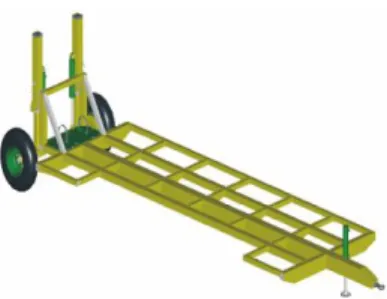
The load and clearance capacity of the seeding machine, for transport of which the tractor trailer was designed (its virtual model see the Fig. 1), are the basic input values for resistance analysis. In order to calculate the load we used the mass of the seeding machine (m = 2 000 kg) and the operation conditions.
Fig. 1 Virtual model of the designed tractor trailer aimed for transport of seeding machines
The resulting load acting on the frame:
N 000 45 10 2,25.2000.
K m g F
V D(9)
where KD (KD = 2,25) is the impact factor (which defines the dynamic condi- tions),
g (g ≈10m.s-2) is the gravity acceleration.
The load is evenly distributed onto the whole construction (see the calculation model in the Fig. 3). The framework is created on the basis of the conceptual design from the rolled sections as a welded construction. The suggested material used for the rolled sec- tions is the steel 11523.1 having the following mechanical properties (FIALA et al., 1990):
− Modulus of elasticity E = 2,1.105 MPa,
− Yield point Re = 343 MPa,
− Breaking strength Rm = 510 ÷ 628 MPa,
− Specific mass = 7,85 .10-3 kg.mm-3,
− Poisson´s material ratio = 0,3.
To create the volume model and consequently to do its analysis the software sys- tems Pro/ENGINEER and Pro/MECHANICA were used. In the resistance and consist- ence analysis the program package works on the basis of the Method of Geometrical Elements (MGE) which is one of the progressive methods of the continuum mechanics.
Both products were developed by the Parametric Technology Corporation in the USA.
The framework was divided into the volume and shell elements (reinforcements).
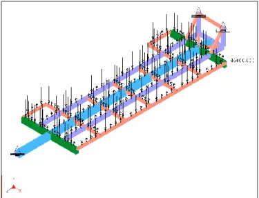
Constructions were defined into three points. In the place of the rod there are reduced three adjustable degrees of freedom in the direction of coordinate axes. On the axle in the point of the fixation of the axle there are two binding points. In both of them four degrees of freedom are reduced (shifts in the directions of the axes y and z, and possible rotations around the axes x and z). Totally 11 degrees of freedom were reduced from the volume model (see the Fig. 1).
Fig. 2 Calculated model of a framework
The model, defined in above-mentioned way, was exposed to a static analysis and subsequent optimization for minimal mass of construction. The static analysis of the initial construction design showed that the stresses (σmax = 71,25 MPa) determined on the construction predetermine application of the optimization aimed at the reduction of the total mass of the construction keeping its dynamic safety and sufficient consistency.
Initial mass of the intuitively designed frame of the chassis was 1368,9 kg.
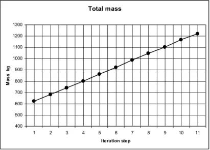
For each beam of the frame 10 sections of the closed thin-walled profile were de- fined and the optimization process itself was done in 10 iterations. As an optimal solu- tion of the framework construction there were selected sections in which the achieved stress was idov = 150 MPa (Fully Stressed Design – FSD).
The survey of the results of optimization calculations is depicted in graphs in Fig. 4 and Fig. 5, where also the dependence of the construction mass change and the reduced stress change from the iteration step can be seen. This process made it possible to reduce the total mass of the welded framework construction to 878,12 kg, i.e. the achieved mass cut-down was 490,78 kg what represents the material mass savings of 35,85 %.
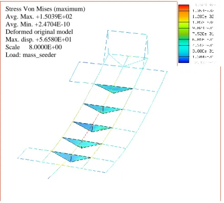
Fig. 3 Behaviour of reduced stress value (Von Mises) – optimized framework Stress Von Mises (maximum)
Avg. Max. +1.5039E+02 Avg. Min. +2.4704E-10 Deformed original model Max. disp. +5.6580E+01 Scale 8.0000E+00 Load: mass_seeder
Fig. 4 Results of optimization calculations
Fig. 5 Results of optimization calculations Conclusions
Comparison of the masses before and after the optimization makes it possible to state that after the application of the so-called Fully Stressed Design (FSD) optimization process the best solution seems to be the use of predefined sections in the 5th iteration
Total mass
400 500 600 700 800 900 1000 1100 1200 1300
1 2 3 4 5 6 7 8 9 10 11
Iteration step
Mass kg
Maximum streess Von Mises
0 100 200 300 400 500 600 700 800 900
1 2 3 4 5 6 7 8 9 10 11
Iteration step
Reduced stress MPa
step for which the section of the main beam UE 20 STN 42 5571 refers. Analogically, it would be possible to determine also the sections of other beams.
After the comparison of the masses of the optimized alternative with the initial so- lution it is possible to express the conclusion that in frame of the chassis the mass sav- ings are mU =1368,9 – 878,12 = 499,78 kg, what is more than 35 %. Taking into account the fact that more pieces of it will be made, then, under the continually increasing prices of materials, this is not a negligible value.
Thus the optimization process proved that using the program system Pro/MECHANICA it is possible to change the cross profiles of the framework beams in such a way, that their minimal mass (the lowest price) is achieved at a sufficient re- sistance and construction consistency.
References
Baier, H. – Seeßelberg, Ch. – Specht, B. (1994). Optimierung in der Strukturmechanik. Vieweg, Wiesbaden 1994. 267 p. ISBN 3-528-08899-0
Daintith, J. (2004). A dictionary of computing. 5 ed., Oxford University Press, 2004. 102 p.
ISBN 9780198608776
Fiala, J. – Bebr, A. – Matoška, Z. (1990). Strojnické tabulky 1. SNTL, Praha 1990. 877 p. ISBN 80-03-00457-8
Kolář, V. – Němec, I. – Kanický, V. (1997). FEM – Principy a praxe metody konečných prvků.
Computer Press, Praha 1997. 401 p. ISBN 80-7226-021-9
Kompiš, v. et al. (1991). Optimalizácia konštrukčných návrhov v spojení s mkp. Edičné stredisko Slovenskej technickej univerzity, Bratislava 1991. 304 p.
Kreith, F. (1998). The CRC handbook of mechanical engineering. CRC Press, 1998.
ISBN 9780849394188.
Laplante, Phillip A. (2005). Comprehensive dictionary of electrical engineering. 2nd ed., CRC Press, 2005. 136 p. ISBN 9780849330865
Matthews, C. (2005). Aeronautical engineer's data book. 2nd ed., Butterworth-Heinemann, 229 p. ISBN 9780750651257
Medvecký, Š. et al. (1999). Základy konštruovania. EDIS – vydavateľstvo Žilinskej univerzity, Žilina 1999. 599 p. ISBN 80-7100-547-9
Meguid, S. A. (1987). Integrated computer-aided design of mechanical systems. Springer, 1987.
ISBN 9781851660216
Žmindák, M. – Sága, M. – Tvarůžek, J. – Husár, Š. (2000). Optimalizácia mechanických sústav.
EDIS – vydavateľstvo Žilinskej univerzity, Žilina 2000. 261 p. ISBN 80-7100-631-9