Implementation of In Silico Biomechanical Methods in Spine Surgery Innovations
Ph.D. thesis
Éltes Péter Endre M.D.
Semmelweis University
Doctoral School of Clinical Medicine.
Supervisor: Áron Lazáry, MD.,Ph.D.
Official reviewers:
Lajos Borbás, Ing. Ph.D.
Árpád Viola, MD., Ph.D.
Head of the Final Examination Committee:
László Hangody, D.Sc.
Members of the Final Examination Committee:
Gábor Skaliczki, MD., Ph.D.
TABLE OF CONTENTS
ABBREVIATIONS ... 4
1. INTRODUCTION ... 6
1.1. Innovation workflow ... 6
1.2. In Silico Medicine ... 7
1.3. Global perspective on the application of 3D technologies in spine surgery ... 8
1.4. Percutaneous cement discoplasty effect on the spinal canal dimensions ... 10
1.5. Lumbopelvic reconstruction after en-bloc sacrectomy ... 11
1.6. Implementation of 3D printed physical models in spine surgery ... 12
1.7. 3D printed patient-specific surgical guide for spine surgical navigation ... 14
2. OBJECTIVES ... 16
3. MATERIALS AND METHODS ... 19
3.1. PART I. Clinical needs finding for 3D technologies, a survey of AOSpine members ... 19
3.1.2 Statistical analysis ... 23
3.2. PART II. A novel method for patient-specific computational analysis of three-dimensional changes in spinal canal dimensions after percutaneous cement discoplasty ... 23
3.2.1. Clinical cohort and CT scan acquisition ... 23
3.2.2. Definition of pre- and postop motion segments’ 3D geometry ... 24
3.2.3. Alignment of the motion segments’ geometry ... 26
3.2.4. Measurement of the neuroforaminal 3D geometry ... 29
3.2.5. PMMA geometry visualisation and thickness measurement ... 30
3.2.6. Statistical analysis ... 31
3.3. PART III. A novel computational method to assess implant deformation and to map bony fusion in a lumbopelvic reconstruction after en-bloc sacrectomy ... 31
3.3.1. Clinical Case ... 31
3.3.2. Postoperative Computed Tomography scan acquisition ... 32
3.3.3. Gait evaluation after total sacrectomy ... 34
3.3.4. Image processing, 3D geometry definition ... 35
3.3.5. Alignment of the implant construct geometries ... 36
3.3.6. Implant deformity measurements ... 37
3.3.7. Mapping of the bony fusion ... 38
3.3.8. Statistical analysis ... 39
3.4. PART IV. Application of 3D printing in spine care ... 41
3.4.1 Definition of the 3D geometry ... 41
3.4.2 3D printing ... 42
3.4.4. Comparison of the 3D physical models printed with FDM or DLP ... 43
3.4.5 Application of 3D printed physical models in surgical planning ... 46
3.4.6 3D data integration in the clinical communication ... 47
3.4.7 Statistical analysis ... 47
3.5. PART V. Affordable patient-specific surgical navigation ... 48
3.5.1. Clinical Case ... 48
4.5.2 Patient-specific 3D geometry definition ... 49
3.5.3. Surgical planning and FE model generation ... 50
3.5.4. Navigation template design, manufacturing and accuracy evaluation ... 54
4.RESULTS ... 57
4.1. PART I. Attitude of spine surgeons towards the application of 3D technologies ... 57
4.2. PART II. Investigation of the PCD surgical technique using 3D methods ... 67
4.2.1 Evaluation of the segmentation procedure ... 67
4.2.2. Motion segments alignment evaluation ... 69
4.2.3. PCD induced indirect decompression volumetric measurement ... 71
4.2.4. PMMA geometry effect on the volumetric change (∆V) of the spinal canal ... 74
4.2.5. Clinical outcome ... 75
4.3. PART III. Investigation of the “Closed Loop” lumbo-sacral reconstruction technique using 3D methods ... 77
4.3.1. Locomotor biomechanics ... 77
4.3.2. Evaluation of the segmentation procedure ... 79
4.3.3. Alignment evaluation ... 79
4.3.4. Implant deformation ... 82
4.3.5. BMD mapping at the fusion site ... 84
4.4. PART IV. Integration of the 3DP physical models in spine care ... 87
4.4.1 Comparison of the FDM and DLP 3D printing technologies ... 87
4.5.1 Navigation template geometrical accuracy and performance ... 94
4.5.2. FEA results ... 97
4.5.3. Proposed surgical technique ... 98
5. DISCUSSION ... 100
5.1. PART I. Need for 3D technologies among spine surgeons ... 100
5.2. The importance of the 3D technologies in the investigation of surgical techniques ... 101
5.2.1. PART II. 3D geometrical change of the spinal canal after PCD ... 101
5.2.2. PART III. Nonrigid reconstruction of the lumbo-sacral junction using the “Closed Loop” technique ... 102
5.3. Application of 3D printing in spine care ... 104
5.3.1. PART IV. 3D printed physical models ... 104
5.3.2. PART V. Affordable 3D printed patient-specific surgical navigation template ... 106
5.4. Future plans for the application of the In Silico Biomechanical methods... 108
6. CONCLUSION ... 111
7. SUMMARY ... 113
8. ÖSSZEFOLGALÓ ... 114
9. BIBLIOGRAPHY ... 115
10. LIST OF OWN PUBLICATIONS ... 125
11.1. Publications that formed the basis of the dissertation: ... 125
11.2 Publication in the field of In Silico Medicine/ Musculoskeletal modelling as co author .... 125
11.2.1. Book chapter ... 126
11.3. Publication in the field of spine surgery as co author ... 126
11. ACKNOWLEDGMENTS ... 127
ABBREVIATIONS
3D three-dimensional
3DP three-dimensional printing ALIF anterior lumbar interbody fusion CAD computer aided design
CT computer tomography
DICOM digital imaging and communications in medicine DLP digital light processing
DSI Dice similarity index FDM fused deposition modeling FE finite element
FEA finite element analysis FEM finite element method FVM final vertebra model HD Hausdorff distance
HDI human development index
I investigator
ICC intraclass correlation coefficient IDD intervertebral disc degeneration inf inferior
LBP low back pain
LLIF lateral lumbar interbody fusion
LP leg pain
MRI magnetic resonance imaging ODI Oswestry Disability Index
OLIF Oblique Lumbar Interbody Fusion
PACS picture archiving and communication system
PMMA polymethyl methacrylate Postop postoperative
Preop preoperative
QCT Quantitative Computed Tomography R&D research and development
SD standard deviation SF:V surface-volume ratio
SPSS statistical package for the social sciences SR surface roughness
STL stereolithography file format
sup superior
T time
Th thoracic
U3D universal three-dimensional file format VAS visual analogue scale
XLIF Extreme Lateral Interbody Fusion
ΔV change in the spinal dimensions after PCD
1. INTRODUCTION 1.1. Innovation workflow
Innovation can be defined as a new idea, creative thoughts, new method, or a new device [1]. A norther perspective present innovation as the application of better solutions that meet new requirements, unarticulated needs, or existing market needs [2]. In the fields of healthcare and medicine innovation plays an important role. In the past Semmelweis by changing the gynaecologist’s handwashing habits saved lives of mothers and opened a new chapter in the field of surgery [3]. Ilizarov’s idea for the external fixator system has influenced the orthopaedic surgical field on both side of the Iron Curtain [4]. The technological innovations in the last decades made possible that the state of the art imaging solutions provided by Magnetic resonance imaging (MRI) or Computed tomography (CT) enables a personalised medical care [5]. Innovation is a key element in the economic development, healthcare system and it has major impact on the society as a whole, therefore the process of innovation has to be explored, and the knowledge about the innovation process has to be implemented in the graduate and postgraduate education [6].
Stanford Biodesign is one of the oldest life science programs, which focuses on training young innovators of biomedical technologies, with focus on medical devices Figure 1, [7]. A major distinction between the more traditional approaches to innovation and the Stanford Biodesign process is the focus on identifying and characterizing the clinical need, instead of the application of a new promising technology. The core idea of the Stanford Biodesign process is defined as “a well-characterized need is the DNA of a great invention”
[8]. In my thesis I am using the workflow’s (Figure 1) first two phases - IDENTIFY/INVENT with the 2/2 stages NEEDS FINDING-NEEDS SCREENING/
CONCEPT GENERATION-CONCEPT SCREENING - to investigate the possible implementation of the In Silico Medicine offered methods in spine surgery, based on a need defined on a global as well as on an institutional level.
Figure 1. The Stanford Biodesign process of Innovating Medical Technologies. The process has 3 phases; identify, invent, and implement. Every phase has 2 specific stages.
The iterative and cyclical process relies on research information, the information’s can demand the returning to prior stages and phases. Activities performed at each stage are presented below the steps in the process. Figure from Yock, Paul G., et al. Biodesign: the process of innovating medical technologies. Cambridge University Press, 2015.
1.2. In Silico Medicine
The emergence of patient focused, holistic medicine generated new technological challenges for medicine that resulted in a new discipline, “in silico medicine”. This new approach places the studying of the human body, thus the biomechanics of the musculoskeletal system into a new context. In silico medicine, including finite-element analysis (FEA) based simulation technologies and three-dimensional printing (3DP), plays a crucial role in the realization of individualized treatments, surgeries [9],[10],[11]. 3DP allows the fast, relatively cheap and accessible production of unique, complex geometries. The
surgical planning, and the preparation of surgeons aided by the 3D printed models in case of highly customized procedures [12],[13],[14],[15], [16].
The first, biomechanical application of the FEA was published by Brekelmans et al.
in 1972 [17], who demonstrated that this method is suitable for analysis of stresses and strains of complex constructions such as the femur under a variety of load situations. In 2002, Fagan et al. [12] reviewed the FEA contribution to our understanding of the spine and its components and its behaviour in healthy, diseased or damaged conditions. In Fagans’
conclusion the method reduces our dependence on animal and cadaveric experiments and is a valuable complement to clinical studies [12]. In 2014, Viceconti discussed the role of contemporary biomechanics in the applications and the development of the so-called Virtual Physiological Human technologies for physiology-based in silico medicine [9]. In Viceconti’s vision computer models can reliably predict certain quantitative changes in health status of a given patient, based on the existing biology and physiology knowledge after it is formulated as a quantitative hypothesis, which can be expressed in mathematical terms [9]. The need for In Silico Medicine offered solutions especially 3D technologies (3D printing, virtual models, and modeling technologies such as FEA) in the field of spine surgery in a global scale has not been investigated yet.
1.3. Global perspective on the application of 3D technologies in spine surgery
New scientific and technological results or methods in the medicine cannot be widespread if the knowledge of the “end users”– spine surgeons in this case – is insufficient. So far, no study has been published about the global perspective of the need, knowledge, and acceptance of 3D technologies (3D printing, virtual models, and modeling technologies such as FEA) in spine surgery. To fill this gap, an online survey research has been conducted in the AOSpine community assessing the level of knowledge and attitude of spine surgeons about the 3D printing and modelling technologies. The global context of the results was expressed in context of the Human Development Index (HDI), an indicator of the human well-being [18], which is based on life expectancy, education and per capita income.
Based on our results, we have determined the information gaps and restricting factors of the development of 3D technologies, whereas the effective knowledge transfer may hold the key to widespread approval. This study serves as the NEED FINDING/NEEDS SCREENING stage in the IDENTIFY phase in the Stanford Biodesign process in my attempt to implement the in silico biomechanical methods in spine surgery innovations.
Figure 2. World map illustrates the categories of Human Development Index by country (based on 2015 and 2016 data, published on 21 March 2017 in the Human Development Report produced by the United Nations Development Program.
After the global context is defined regarding the 3D technologies, I have been investigating two surgical methods developed in the National Center for Spinal Disorders (NCSD), Budapest, Hungary, the Percutaneous cement discoplasty and the Closed Loop lumbopelvic reconstruction technic after en-bloc sacrectomy by applying research methods from the field of In Silico Medicine. The global perspective given by the survey study raised the need for strategies to implement 3D printing and FEA in cost effective way.
1.4. Percutaneous cement discoplasty effect on the spinal canal dimensions
Musculoskeletal disorders are the cause of nearly 166 million years lived with disability [19]
worldwide, with low back pain and neck pain representing 69.9% of the cases [19],[20]. The incidence of such diseases is likely to increase due to population ageing; therefore, their attendance is becoming a growing burden on the healthcare system [21],[22].
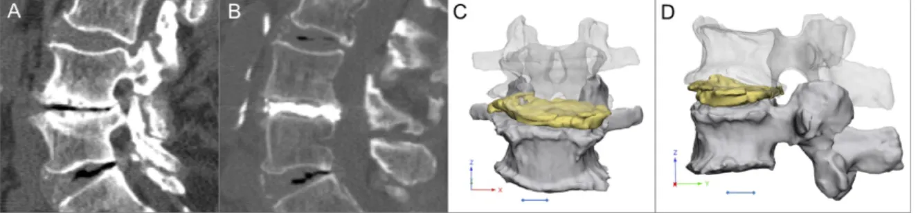
The intervertebral disc degeneration (IDD) is an age-related degenerative process resulting in biomechanical and structural changes of the intervertebral discs [23]. The degree of IDD is defined by the MRI based Pfirrmann grading system [24]. The terminal disc degeneration (Pfirrmann V) is characterised by total disorganisation of the intervertebral tissue, the complete resorption of the nucleus pulposus, resulting in the vacuum phenomenon [25],[26],[27]. Intervertebral discs act as transmitting units and shock absorbers, distributing the load of body weight and muscle activity through the spinal column [28]; therefore, degeneration related structural changes will lead to biomechanical dysfunctions [29], such as segmental instability. The decreasing disc height will result in continuously decreasing spinal canal dimensions which in concert with the cyclic repetitive alternation of the foramen due to movement, lead to the development of chronic radiculopathy via compression of the nerve roots; which in turn will result in local and irradiating pain during axial loading [30]. Curative treatment of the pain requires treatment of the segmental instability; however, in elderly patients’ surgical possibilities are limited due to severe comorbidities. Therefore, the minimally invasive procedures have become the preferred surgical option. Percutaneous cement discoplasty (PCD) is such a procedure, where the vacuum space in the intervertebral disc is filled out with percutaneously injected PMMA (Polymethylmethacrylate) Figure 3.
PCD provides a segmental stabilizing effect and indirect decompression of the neural elements due to the increase of the spinal canal dimensions. The technical details, the clinical effect and safety issues of the procedure have been previously published and the use of the technique has been also supported by a radiological prospective study [31],[32]. However, the changes in the spinal canal (central canal and neuroforamen) dimensions have not been quantified so far, because of the challenging methodological issues.
2D parameters (disc height, foramen height/diameter, foramen cross-sectional area, central canal diameter, central canal cross-sectional area, or segmental lordosis angle) in recent studies [33],[34],[35] which could lead to possible biases. To accurately measure the real, three-dimensional (3D) changes of the spinal canal after PCD procedure, I have aimed to develop a generalisable procedure based on patient-specific 3D computational, volumetric measurements.
.
Figure 3. Percutaneous cement discoplasty, A Computed Tomography (CT) images (sagittal view) of a patients with advance degenerated disc (vacuum sign) LIV-LV level, B postoperative CT images (sagittal view) of the treated LIV-LV segment, the disc space is field with PMMA (Polymethylmethacrylate), C, D coronal and sagittal view of the LIV- LV motion segment 3D geometry (LIV vertebra transparent) with the injected PMMA geometry, scale bar=1cm
1.5. Lumbopelvic reconstruction after en-bloc sacrectomy
Sacral tumours are rare pathologies, but their management generally creates a complex medical problem [36]. Primary benign and malignant tumors of the sacrum are 2%
to 4% of all primary bone neoplasms and 1% to 7% of all primary spinal tumors [37]. Most common primary sacral tumors are chordomas, representing 40% of all primary sacral neoplasms [38]. Chordoma is a malignant mesenchymal tumor with notochordal origin [39].
Surgical treatment is one of the most challenging fields in spine because of the complicated anatomy of the sacral site. In most cases, only radical surgical procedures, such as partial or total sacrectomy, can guarantee optimal local control, but several problems such as bowel, bladder and sexual dysfunction, infection, massive blood loss and spino–pelvic instability can be associated with sacral resections [40],[41]. Beyond the primary goal of the surgery
(eg. wide resection of the tumor mass), the optimal spino-pelvic reconstruction focused on biomechanical stability and soft-tissue restoration is also indispensable [42]. Several different techniques were developed for the lumbopelvic stabilization after sacropelvic tumor resection, however, long-term follow-up data and comparative studies of the different techniques are rare or still missing [43]. There is no gold standard and relatively high complication rates are reported with all reconstruction strategies [43], [44]. The ‘‘en-bloc’’
resection of a sacral chordoma by performing a total sacrectomy with soft tissue and bony reconstruction and lumbopelvic stabilization can be achieved by the ‘‘closed loop’’ technique [36],[43]. The technique uses a ‘‘U’’ shaped rod which is attached to the iliac and transpedicular screws to rebuild the spinopelvic connection (Figure 4). During the development of the investigated reconstruction technique the non-rigidity was a key concept in order to allow shock absorption during cyclical loading. However, the hypothesis was not tested if the construct deforms over the time. Here we aimed to develop a generalisable method based on patient-specific 3D geometries derived from CT scans in order to investigate the implant construct deformation over 6-year follow-up (FU) for a reconstruction technique.
1.6. Implementation of 3D printed physical models in spine surgery
Three-dimensional printing technologies transformed product manufacturing fundamentally [45], foreshadowing a new technological revolution [46]. Its medical utilizations, especially surgical application of 3D printed technologies aids the preoperative planning, saves time in the operating room and provides patient-specific solutions for complex cases through personalized implants [47],[48]. Besides surgical planning 3D printed physical models play a crucial role in medical education and patient communication as well, by promoting a better understanding of complex morphological changes [49],[48],[50].
However, the additional costs and time-consuming production of 3D printed physical models with current technologies are hindering its widespread use in hospitals [51].
Figure 4. “Closed Loop” lumbo-sacral reconstruction technic after total en-bloc sacrectomy. A extended tumor mass affecting the whole sacrum. B geometrical change in the 3D geometry of the spino pelvic junction after en-bloc total sacrectomy. The iliac bone is cut by an oscillating saw bilaterally; the medial cortical surface of the iliac bone is left on the specimen. The lumbosacral facet joints with the intervertebral disc are removed.
The dural sac (together with the cauda equina) is cut through immediately below the LV.
The distance between the LV vertebra and the iliac bone is reduced (direction of the arrows). C in the LIII–V vertebral body and bilaterally into the iliac bones screws are inserted and connected with a single 5.5 mm diameter ‘‘U’’ form rod according to the patient’s reduced (C) local dimensions and attached to the screws. The red areas mark the place for the artificial bone substitute, mixed with autologous bone graft. D the re- established connection, between the lumbar spine and the pelvis. At the side of the graft (D) after two years bony fusion is expected.
Moreover, there is a continuously increasing strain on healthcare providers due to global demographic shifts such as population increase, and societal change such as the rise of life expectancy [52],[53]. Therefore, the development of cost effective, sustainable strategies related to clinical application of 3DP technologies are not only highly desirable but decisive.
Currently, there is an increasing interest in the healthcare market of commercial 3D printing services [54], each providing 3D printers with different technologies and technical parameters at a widely differing price-range. The clinician and the hospital management face the decision of choosing one of these services and are confronted with the task of implementing it with the available resources. However, evidence-based reports which can potentially offer guidance on these issues are absent in the literature.
In my thesis I present a method to compare the geometrical accuracy of two 3D printing technologies for printing spine physical models. Advantages and disadvantages were weight up in an entry level technology (cost effective, most affordable) with a higher category technology (more precise, more expensive). We also reveal an institutional strategy of the application of 3D printed physical models by presenting a clinical case, where a model printed with the entry level technology was used in the preoperative planning.
1.7. 3D printed patient-specific surgical guide for spine surgical navigation
Spinal fixation is a routine procedure for the treatment of unstable spine due to trauma, congenital malformations, degenerative diseases, and tumours [55]. The accurate placement of screws in the spine is challenging, given the risk of damage to neighbouring anatomical structures (spinal cord, nerve roots, arteries, veins) [2], [57]. Computer-assisted surgery (CAS) has been adopted as a safe and accurate guiding system for the placement of pedicle and lateral mass screws in the spine [58]. CAS navigation systems use optical tracking via infrared cameras incorporating 3D geometries from pre-operative CT scans or in combination with fluoroscopy-based imaging [59], [60] or intraoperative CT scans [61].
Optimal registration of the spine geometry to the navigational instruments is crucial for
obtaining the intraoperative CT or fluoroscopy images may cause CAS registration errors, which can result in screw malposition. This phenomenon cannot be completely excluded even with state of the art intraoperative CT technology [61]. 3D printed patient-specific surgical navigation templates are accurate [62], [63], decrease surgical time, reduce intraoperative x-ray exposure [64] and can be more accessible compared to traditional CT or fluoroscopy-based systems [65], [66]. The decline in the costs of 3D printing technology is expected to continue due to its continuous and fast development [67], [68], [69]. However, in less developed areas of the world, where complex spinal deformity is relatively common and advanced CAS technology is not available [64], [70] 3D printed templates are still not as widely implemented in the clinical practice, as it would be desirable.
Revision surgeries are challenging especially if an implant related failure is complicating the clinical situation. The lumbo-sacral area has a special local anatomy. In the S1 segment the convergent bicortical screw trajectory provides a superior anchoring compared to any other directories, but the proper insertion of the new screws in a revision surgery can be impossible without surgical navigation. In my thesis, I am representing a case who has raised the clinical need for the development of a computer-aided design (CAD) and finite-element analysis (FEA) combined method for affordable spine surgical navigation with 3D printed customized drill guide.
2. OBJECTIVES
The general aim of my PhD work is to investigate the implementation of In Silico Biomechanical Methods in Spine Surgery Innovations.
In the first part of my PhD thesis, I pursue to answer the question of what determines the acceptance rate and the factors which stand against the wider spread of the 3D technologies in spine surgery (Eltes et al., 2019). For this purpose, I specifically addressed the following questions in a survey-based study in five thematic chapter:
1. What is the demographic of the respondents (country of residence, details of spine surgical practice, basic knowledge of 3D technologies)?
2. Personal use of 3D printed or virtual 3D models
3. Use and attitude towards 3D technologies in surgical navigation
4. Use and attitude towards the advanced manufactured (3DP) and patient-specific implants
5. What is the future and limitations of the 3D technologies in spine surgery?
Investigation of these problems defined a global context regarding 3D technologies.
Therefore, in the second and third part of my PhD work, I have been studied two surgical methods developed in the NCSD the PCD and the Closed Loop lumbopelvic reconstruction technique.
In part two, I aimed to develop a generalizable procedure based on patient-specific 3D computational, volumetric measurements to evaluate the geometrical change of the spinal canal after PCD treatment. For this, the following specific questions have been asked:
1. How can the complex 3D geometry of the spinal canal be defined?
2. How can the geometrical change in the spinal canal due to PCD be measured?
3. How reliable and repeatable is the developed method?
4. What is the relationship between the PCD induced volumetric change in the spinal canal and the PMMA volume, surface and surface-volume ratio?
5. What is the relationship between the PCD induced volumetric change and the
In part three, I aimed to develop a generalizable method based on patient-specific 3D geometries derived from CT scans in order to investigate the implant construct deformation over 6-year follow-up (FU) for a patient who underwent sacrectomy and Closed Loop reconstruction. The following specific questions were addressed:
1. How can we define the complex 3D geometry of the implant construct and the pelvic bone?
2. How can we measure the deformation of the implant construct over the FU?
3. How can we map the bony fusion process?
4. How reliable and repeatable is the developed method?
5. What is the relationship between the postoperative days and the implant construct deformation in the three anatomical planes (coronal, sagittal, axial)?
The global perspective on the attitude of the spine surgeons towards the application of 3D technologies given by the survey study raises the need for strategies to implement 3D printing and FEA in the clinical environment in an affordable way. Part four of my thesis addresses the need for the application of affordable 3D printing technology for spine physical models (Eltes et al., 2020). Here, I developed an institutional strategy for application of the 3D printed physical models and I addressed the following specific questions:
1. How can we create an accurate 3D virtual model of the patient-specific spine?
2. How can we evaluate the geometrical accuracy of a 3D printing technology?
3. Can an affordable printing technology provide accurate 3D spine physical model compared to a more expensive, more accurate printing technology?
4. Can we implement the patient specific virtual models in the clinical communication?
5. How can we use a patient-specific physical model in presurgical planning?
Part five of my thesis addresses the clinical need for the development of computer- aided design (CAD) and finite-element analysis (FEA) combined method for affordable spine surgical navigation with a 3D printed customized drill guide to allow safe pedicle screw insertion in challenging situations. For this, I asked the following specific questions:
1. How can we provide a patient-specific surgical guide in the case of revision surgery, where a broken SI screw creates a challenging geometrical situation for a new screw insertion?
2. Can we evaluate and integrate the local bone biomechanical properties for the screw insertion and for the guide design?
3. Can we reduce the finite element model running time and preserve reliable results?
4. How can we manufacture the guide in a cost-efficient way?
5. How can we test the accuracy of the guide before surgery without cadaveric models?
Contributions:
In my thesis in parts I, II, III, IV, V the research design, acquisition of data, analysis and interpretation of data, and writing the manuscripts for publications based on the Parts (I- V) was done by myself under the guidance of Áron Lazáry. However, in the following paragraph I specify the detailed contribution of my co-workers in the different Parts.
In PART II. of my thesis Lászlo Kiss was the second investigator (I2). Máté Turbucz was the second Investigator (I2) in PART III., and Jennifer Fayad the third investigator (I3).
Jennifer Fayad processed the data of the gait analysis and prepared Figure 34. In PART IV.
Vivien Leskó was the second investigator (I2). Tibor Csákány integrated the 3DPDF files containing the virtual patient-specific models in the internal institutional database. Benjámin Hajnal in PART V., created the visualization for the proposed surgical technique summarized in Figure 48.
3. MATERIALS AND METHODS
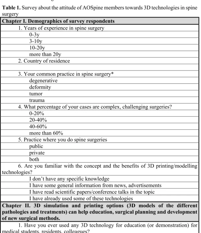
3.1. PART I. Clinical needs finding for 3D technologies, a survey of AOSpine members In October 2016, an online survey (Table 1.) was sent out a single time to all AOSpine members on the mailing list.
Table 1. Survey about the attitude of AOSpine members towards 3D technologies in spine surgery
Chapter I. Demographics of survey respondents 1. Years of experience in spine surgery
0-3y3-10y 10-20y
more than 20y 2. Country of residence
3. Your common practice in spine surgery*
degenerative deformity tumor trauma
4. What percentage of your cases are complex, challenging surgeries?
0-20%
20-40%
40-60%
more than 60%
5. Practice where you do spine surgeries public
private both
6. Are you familiar with the concept and the benefits of 3D printing/modelling technologies?
I don’t have any specific knowledge
I have some general information from news, advertisements I have read scientific papers/conference talks in the topic I have already used some of these technologies
Chapter II. 3D simulation and printing options (3D models of the different pathologies and treatments) can help education, surgical planning and development of new surgical methods.
1. Have you ever used any 3D technology for education (or demonstration) for medical students, residents, colleagues?
occasionally, 3D virtual models occasionally, 3D printed models
frequently, 3D virtual or printed models
2. Have you ever used 3D virtual models or printed models for surgical planning or for the development of a surgical technique (e.g. by demonstrating the difficult anatomical situation or the challenging surgical steps)?
never
occasionally frequently
other (please specify)
3. What is the main barrier of the frequent use of such techniques in your clinical/educational practice? *
no or limited knowledge about the possibilities and requirements no or limited access to 3D modelling software
no or limited access to 3D printing costs of 3D modelling/printing
I am not interested in these technologies
Chapter III. 3D modelling/printing can be used to produce patient- and condition specific surgical navigation guides, particular instruments to improve the safety and efficacy of challenging procedures (resections, osteotomies, difficult screw insertion etc).
1. Intraoperative 3D navigation systems can reduce the complications and the morbidity of spinal surgeries. Do you use any 3D navigation system or tool in your clinical practice?*
not at all
occasionally (CT or fluoro based system) regularly (CT or fluoro based system) occasionally (3D printed surgical guide) regularly (3D printed surgical guide) 2. If not what is the reason?*
lack of knowledge high purchasing price high maintaining costs
too complicated use (longer surgery, need of a technician, etc) lack of confidence
I do not see its necessity in my practice other:
3. If you use any 3D navigation or if you would have the possibility of use, how many percentages of your surgeries would you use the technology in?
<10%
4. Have you ever experienced or felt that a specific, unique surgical instrument (e.g. a particular chisel, courette or screwdriver) would have helped the surgery?
no occasionally frequently
5. What do you think about the acceptable cost of a unique, 3D printed surgical instrument in your country and clinical setting?
less than 10% of the direct cost of the surgery
no more than twice of a similar, but traditional product comparable to the cost of a pedicle screw
significant extra cost is acceptable
Chapter IV. 3D modelling and printing technologies can help to develop the next generations of spinal implants. Advanced manufactured general (eg. porous) and patient-specific implants can have a significant role in the future personalized medicine.
1. Have you ever used any advanced manufactured (3D printed) implant?
never
occasionally frequently
2. Where do you see the possible advantage of the use of advanced manufactured implants?
all implanted surgeries because a general or patient-specific advanced manufactured implant can provide better
clinical outcome even in case of a standard pathology
challenging surgeries (e.g. tumor resection) and compromised anatomy or biology
only in complex cases where patient-specific implant would be required none of the spinal surgeries
3. What do you think how many of your cases could benefit from the use of advanced manufactured (3D printed general or patient-specific) implants?
<10%
10-25%
25-50%
>50%
other (please specify)
4. How do you see what is the main barrier of the spreading of advanced manufactured (3D printed) implants?*
limited knowledge about the possibilities among the surgeons limited access to 3D modelling and/or printing solutions high cost of modelling/printing
unclear regulations
lack of confidence, limited evidence
5. What do you think about the acceptable cost of an advanced manufactured implant in your country and clinical setting?
same as a traditional implant
no more than twice of traditional implants
high cost is acceptable because of the personalized approach
a significant extra cost is acceptable because a 3D printed implant can provide better clinical outcome
an advanced manufactured implant can reduce the total cost of the surgery at least in selected cases
Chapter V. General impression
1. What do you think about the role of 3D printing/modelling technologies in spinal surgery?
no real future – too complicated and expensive
an option only for very limited applications, individual cases a promising, feasible option for the near future
revolutionary
other (please specify)
2. What do you think what are the main barriers of the spreading of 3D printing/modelling technologies?*
“distance” between engineers and surgeons
“distance” between the hospital and the printing/designing facility
surgeons are not aware of the possibilities provided by 3D printing/modelling expensive technology
market are full with traditional solutions
surgeons are not motivated to use advanced manufactured implants process of a patient-specific surgery is time-consuming
3. Other specific comments:
*Note: multiple choice
The survey was open for two months and a single answer was permitted per email address.
The questionnaire included 21 multiple choice or ordinal scale questions, being divided on thematic chapters (one page each) as follows: (I.) question I/1-6 we collected demographic data of the respondents (country of residence, details of spine surgical practice, basic knowledge of 3D technologies); (II.) questions II/1-3 focused on the personal use of 3D printed or virtual 3D models; (III.) questions III/1-5 focused on the use and attitude towards 3D technologies in surgical navigation; (IV.) questions IV/1-5 investigated the advanced manufactured (3DP) and patient-specific implants; in chapter (V.) we raise questions V/1-2
representing the plausible level of acceptance (acceptance score) of 3D technologies in spine surgery. The influence of geographical location (AOSpine region), spine surgical practice, experience, etc. on the acceptance score was analyzed statistically. Participants of our survey were grouped based on the HDI of their country of residence and survey results were analyzed in the context of this parameter too.
3.1.2 Statistical analysis
For statistical analyses, Spearman correlation, non-parametric tests, and Chi-square tests were applied depending on the distribution of the variables. Statistical tests were performed using SPSS and p<0.05 was considered as significant.
3.2. PART II. A novel method for patient-specific computational analysis of three- dimensional changes in spinal canal dimensions after percutaneous cement discoplasty 3.2.1. Clinical cohort and CT scan acquisition
We performed a retrospective analysis of prospectively collected data. The study was approved by the National Ethics Committee of Hungary, the National Institute of Pharmacy and Nutrition (reference number: OGYÉI/163-4/2019). Informed consent was obtained from all participants.
The cohort consisted of 10 patients (74 ± 7.7 years old), who underwent primary single or multilevel PCD (16 motion segments in total) at a tertiary care spine referral centre (Table 2). All presented operative procedures were performed by a single surgeon (GJ).
Preoperative (preop), and postoperative (postop) 6-month follow-up results were collected and analysed using the patient- reported outcome questionnaire Oswestry Disability Index (ODI) and with visual analogue scale (VAS) for leg pain (LP) and low back pain (LBP).
Quantitative Computed Tomography (QCT) scans were performed pre- and postoperatively, with a Hitachi Presto CT machine using an in-line calibration phantom, and a protocol previously defined in the MySpine project (ICT-2009.5.3 VPH, Project ID: 269909) with an intensity of 225mA and voltage of 120kV [71], [72]. Images were reconstructed with a voxel size of 0.6x0.6x0.6 mm3. Based on the QCT images, Hounsfield Units can be converted into bone mineral density (BMD) equivalent values, necessary for creating finite element (FE)
models. In this study the QCT images were used as conventional CT images without any conversion.
The data were exported from the hospital PACS in DICOM file format. To comply with the ethical approval the patient data protection, anonymization of the DICOM data was performed using the freely available Clinical Trial Processor software (Radiological Society of North America, https://www.rsna.org/ctp.aspx) [73].
Table 2: Clinical cohort
3.2.2. Definition of pre- and postop motion segments’ 3D geometry
In order to establish the 3D vertebral geometry of the pre- and postop motion segments and the injected polymethyl methacrylate (PMMA) geometry, a segmentation
(Mimics Research, Mimics Innovation Suite v21.0, Materialise, Leuven, Belgium) were used. (Figure 5).
Figure 5. 3D geometry definition of pre- and postop motion segment geometries and of the injected PMMA geometry. A during the segmentation process the bone volume is first separated from the surrounding soft tissue by thresholding of the Hounsfield units’ levels of the 2D CT images (sagittal view). The resulting colored mask (preop, red; postop, yellow) voxels represent the 3D volume of the vertebra, and the blue voxels the PMMA, respectively. B from the mask, a triangulated surface mesh is generated, and a smoothing is applied (iteration: 6, smooth factor: 0.7, with shrinkage compensation). C uniform remeshing process was applied (target triangle edge length 0.6 mm, sharp edge preservation, sharp edge angle 60°). Scale bar length 5mm.
During the segmentation process the bone volume was first separated from the surrounding soft tissue by thresholding of the Hounsfield units’ levels. The resulting masks (group of voxels) where homogenously filled by preserving the outer contour of the geometrical border in 2D. From the mask, a triangulated surface mesh was automatically generated. On the 3D geometries surface smoothing was applied (iteration: 6, smooth factor:
0,7, with shrinkage compensation). Furthermore, uniform remeshing process was applied (target triangle edge length 0.6 mm, sharp edge preservation, sharp edge angle 60°) for all the vertebra and PMMA geometries. To evaluate the accuracy of the segmentation process, we calculated the Dice Similarity Index (DSI) [75, 76]. The DSI quantifies the relative volume overlap between two segmentation procedures as follows:
DSI=(2·V(I₁∩I₂))/(V(I₁)+V(I₂)), V is the volume of the voxels inside the binary mask (number of voxels multiplied with the voxel size; in mm3), and I1 and I2 are the binary masks from two segmentation processes (performed by two investigators (I), 1 and 2). The DSI values range between 0 ± 1, one denoting a perfect match. The vertebral geometry segmentation accuracy was evaluated by random selection of 6 preoperative and 6 postoperative vertebral geometries (Microsoft Office Professional Plus 2016, Excel, RANDBETWEEN function). All 12 vertebras were segmented by a second investigator (I2) and the second segmentation was compared to I1 after which the DSI was defined. The PMMA segmentation evaluation was done by repeating all the 16 measurements by I2 and then the DSI was calculated.
3.2.3. Alignment of the motion segments’ geometry
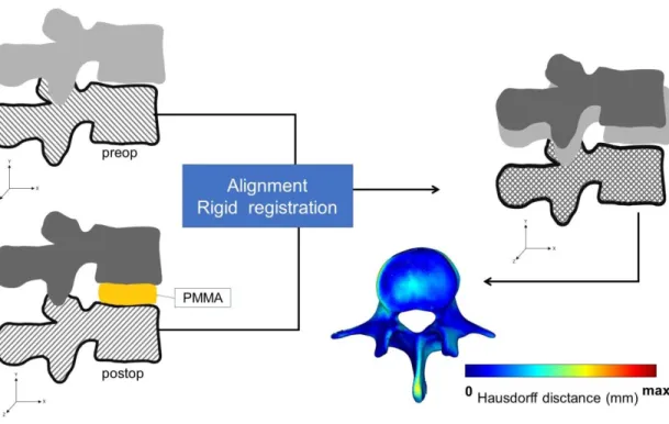
To detect the PCD induced changes in the postop motion segment, the pre- and postop vertebral geometries were aligned in the same coordinate system. For this, preop 3D data sets were transposed into the same coordinate system with the postoperative data. Pre- and postop caudal vertebra surface mesh models of the treated motion segments were used as reference geometry (Figure 6).
Figure 6. Alignment of the preop motion segment vertebral geometry to the postop geometry. The alignment of the caudal vertebra was performed using control points (as shown in Figure 7) and rigid surface registration algorithms were applied. The process created a common coordinate system for the preop and postop motion segments with nearly identical boundaries for the caudal vertebras. The Hausdorff Distance was used as a quality measure for the alignment process at the caudal vertebra.
A control points based rigid registration algorithm was used via Mimics® software.
The 18 control points corresponded to easily identifiable anatomical landmarks at the caudal vertebra or sacrum (Figure 7).
To evaluate the accuracy of the registration and alignment procedure the Hausdorff Distance (HD) was measured with the MeshLab1.3.2 software [77] (an open source free software: http://www.meshlab.net) Metro tool [78] (Figure 6) at the level of the aligned caudal preop and postop vertebras. The HD represents the maximum distance between two points (triangle vertex) of two sets, both from corresponding sections of the meshes (i.e.: the HD is expected to be equal to zero in case of a perfect alignment of absolute symmetrical
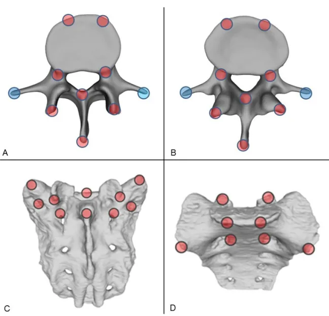
Figure 7. Selection of control points for rigid surface registration. Ten control points were selected from the superior (A) and eight from the inferior (B) reference regions of the vertebra and from the aligned geometry, respectively. For the sacrum ten control points were selected from the superior-dorsal (C) and eight from the superior-ventral (D) regions of the reference and from the aligned geometry, respectively. The filled red circles represent the selection areas of the registration points, the filled blue circles represent
The HD values were calculated at the vertices of the triangulated surface meshes as follows: ℎ(𝐴𝐴,𝐵𝐵) =𝑚𝑚𝑚𝑚𝑚𝑚𝑎𝑎𝑎𝑎𝑎𝑎{𝑚𝑚𝑚𝑚𝑚𝑚𝑏𝑏𝑎𝑎𝑏𝑏{𝑑𝑑(𝑚𝑚,𝑏𝑏)}}; where A is the postop mesh; B is the preop reference mesh; a and b are points of sets A and B respectively, and d(a, b) is the Euclidean metric between these points. The alignment of the pre and postop motion segments was performed by two investigators (I1, I2) and two aligned datasets were created with 16-16 motion segments each. The HD measurements where performed for all the 16 registered motion segments for both investigators.
3.2.4. Measurement of the neuroforaminal 3D geometry
After alignment, the change in spinal canal geometry, induced by the injected PMMA in the intervertebral space during the PCD procedure, was defined for the two datasets (aligned by I1, I2). A measurement cylinder was created using Mimics® software analyse module. The cylinder was inserted in the virtual coronal axis of the neuroforamens (coronal plane). Its length was defined at 90 mm, while the radius of the cylinder was set by the investigators uniquely in each patient and segment (Table 4) in a way to fill the neuroforamens’ volumes and the central canal in pre- and postop 3D geometries of the motion segments (Figure 8).
The overlapping volumes between the cylinder and the motion segment 3D geometry were subtracted (Boolean operation/Minus). The change in the subtracted cylinder volumes represents the spinal canal dimension Vpreop= 3D Cylinder– (3D Cylinder- Preop 3D motion segment), and Vpostop= 3D Cylinder– (3D Cylinder- Postop 3D motion segment). The change in the subtracted cylinder volumes represents the indirect decompression effect of the surgical procedure and it is defined as ∆V (∆V = Vpostop - Vpreop) (Figure 8). To determine the repeatability and accuracy of the measurements, intra an inter-rather reliability analysis of the two Investigators (I1, I2) at two different time points (T1, T2) was determined (see Statistical analysis).
Figure 8. Measurement of the change in the neuroforaminal geometry induced by the PCD.
After alignment, the pre- and postoperative motion segments shared a common caudal vertebra. The cranial vertebra geometrical position has changed due to the lifting effect of the PMMA. Two identical cylinders were introduced in the neuroforaminal and central canal regions of the pre- and postop. motion segments. Vpreopand Vpostoprepresent the subtraction of the overlapping vertebral geometry from the initial cylinder geometry. The indirect decompression effect of the PCD is defined as ∆V (∆V = Vpostop - Vpreop).
3.2.5. PMMA geometry visualisation and thickness measurement
The 3D geometry of the intervertebral PMMA for the 16 treated motion segments were defined during the segmentation process by a uniformly remeshed triangulated surface mesh (Figure 5). The surface mesh defines the geometry and determines the surface and the
The thickness was defined at the level of every triangle element of the surface mesh as the perpendicular distance from the element midpoint to the other wall (surface) off the geometry.
3.2.6. Statistical analysis
The data management was performed in Microsoft Office Professional Plus 2016 (Microsoft, Redmond, Washington, United States). All statistical tests were performed with SPSS statistical package version 23 (SPSS Inc, Chicago, IL). Due to small sample size, normality test of the data is expected to have little power, thus we opted to apply non- parametric tests. The HD measurements cumulative probability plots (Supplementary Fig.2) were created with SigmaPlot 12 (SSI, San Jose, California, United States). Inter-rater (I1 vs I2) reliability was determined by Intraclass Correlation Coefficient (ICC) estimates and their 95% confident intervals (CI) were calculated based on a mean-rating (k = 2), absolute- agreement, 2-way mixed-effects model. Intra-rater (I1T1 vs I1T2, I2T1 vs I2T2) reliability was determined by ICC estimates and their 95% confident intervals were calculated based on a single measurement, absolute-agreement, 2-way mixed-effects model. The statistical difference in the change of spinal canal volume, ODI, LP and LBP pre-, and postop was assessed by Paired Sample Wilcoxon signed ranked test (p ≤ 0.05, Figure 32). The relationships between the PMMA and the mean volumetric change (∆V); PMMA surface and
∆V; PMMA surface-volume ratio and ∆V were defined using the Spearman's rank correlation (Figure 33). The relationships between the ∆ODI (preop – postop) and the ∆V; ∆LP (preop – postop) and the ∆V, ∆LBP (preop – postop) and the ∆V were defined using the Spearman's rank correlation (Figure 33).
3.3. PART III. A novel computational method to assess implant deformation and to map bony fusion in a lumbopelvic reconstruction after en-bloc sacrectomy
3.3.1. Clinical Case
The patient (Figure 9) case and surgery was presented at the European Spine Journal, Open Operating Theatre (OOT) platform [79], [80]. The 42-year-old male patient had mild and non-specific low back pain for 4–5 years. He had experienced minor problems with
defecation and urination for 1 year and a palpable lump had been observed for some months in the sacral region. The neurological examination showed normal motor and sphincter function but a mild hypaesthesia in the perianal region. Radiological examinations revealed an extended tumor mass affecting the whole sacrum with significant soft tissue extension to the retroperitoneum and cranially involving the paravertebral muscles as far as the LIII spinal level on the right side (Figure 9). Open biopsy procedure based Histological examination reweld the diagnosis of chordoma. Total ‘‘en-bloc’’ sacrectomy combined with soft tissue and bony reconstruction together with lumbopelvic stabilization (‘‘closed loop’’ technique) was performed to remove the tumor. Artificial bone substitute (ACTIFUSE®) was placed between the LV body and the iliac crest bilaterally after refreshing and preparing well bleeding spongious bony host surfaces (Figure 4C). The large defect of the body wall between the LV vertebral body and the coccygeal ligamentous complex was covered by Dacron mesh (anchored to the bony landmarks: LV vertebral body, tuber ossis ischii and iliac bone). Finally, the wound closure was performed by creating bilaterally m. gluteus maximus rotatory flaps.
3.3.2. Postoperative Computed Tomography scan acquisition
We performed a retrospective analysis of retrospectively collected postoperative (postop) Computed Tomography (CT) data. The study was approved by the National Ethics Committee of Hungary, the National Institute of Pharmacy and Nutrition (reference number:
OGYÉI/163-4/2019). Informed consent was obtained from the participant. The data set consisted of 12 CT covering a 6-year follow-up period (FU) (Table 3). The CT scans were performed with the same CT machine (Hitachi Presto, Hitachi Medical Corporation, Tokyo, Japan) with an intensity of 225mA and voltage of 120kV. The data were exported from the hospital PACS in DICOM file format. To comply with the ethical approval the patient data protection, deidentification of the DICOM data was performed using the freely available Clinical Trial Processor software (Radiological Society of North America, https://www.rsna.org/ctp.aspx) [73].
Figure 9. Pre- and postop imaging of a 42 years old male patient how underwent total en- block sacrectomy and received a Closed Loop spinopelvic reconstruction. A, B preop T2, MRI images of a large sacral chordoma (A sagittal, B axial plane) The extended tumor mass effected the whole sacrum with significant soft tissue extension to the retroperitoneum and cranially involving the paravertebral muscles. C, D Standing X-ray images of the patient at 6 month FU (C sagittal, B coronal plane). E, F CT scan at 24 month CT images, signs of bony fusion are visible between the L.IV,V vertebra and the iliac bone ( E posterior view of the 3D rendered CT images, F coronal view at the fusion site)
Table 3. Retrospectively collected CT scans
CT (Computer Tomography)
3.3.3. Gait evaluation after total sacrectomy
During the surgery the lumbosacral intervertebral disc was resected, and the dural sac (together with the cauda equina) was cut through immediately below the L.5 origins.
Bilaterally the cranial and ventral ligaments of the S.I joints and the nerve roots (bilaterally below the S.1) were both cut through at the lateral aspect of the tumour [80]. However, the patient was able to walk with crutches at 3-month (m) FU, and without any assisting device at 12m FU. In order quantify and evaluate the gait of the patient at 6-year FU a gait analysis was performed. Gait data was acquired while the patient walked along a straight path at a self-selected speed. The subject was fitted with a full body VICON plug-in-gait marker setup.
Three-dimensional kinematic data was recorded using a 6-camera system (MXT40, VICON, UK). Kinetic data was acquired using one force platform (AMTI OR6, USA) mounted halfway along the path. Lower limb kinematics and kinetics were calculated using NEXUS (VICON, UK) and compared to normative data.
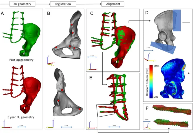
Figure 10. Postop CT scan-based geometry definition and alignment. A Thresholding based segmentation was performed on the postop CT scan in order to define the left iliac bone and the implant construct. B 8 landmarks corresponding to anatomical landmarks where used for the simultaneous registration of the iliac bone and implant construct geometry. C every postop iliac bone + implant construct geometry was registered to the first postop geometry. D the Hausdorff Distance was used as a metrics for the alignment accuracy evaluation. Geometrical reduction of the caudal and posterior part or the registered iliac bones was performed. E the trans iliac screws body’s geometry overlapped after the iliac bone registration. The axis of the iliac screws were considered to be collinear and coincident.
3.3.4. Image processing, 3D geometry definition
In order to define the deformation of the Closed Loop implant construct we defined the construct 3D geometry and arbitrary the left iliac bone 3D geometry in every CT data set.
alignment a symmetric geometry reduction was performed by a cube substraction, in order to exclude the geometrical difference, the same substraction was performed for all geometries at the Ischial ramus, where the last axial CT slice ended for the first postop scan (for the rest all the pelvis was covered in the scan) (Figure 10D.) Segmentation process was performed on the 2D CT images [74]. For this, the thresholding algorithm and manual segmentation tools (erase, paint, fill etc.) in Mimics® image analysis software (Mimics Research, Mimics Innovation Suite v21.0, Materialise, Leuven, Belgium) were used. (Figure 10A). During the segmentation process the bone volume was first separated from the surrounding soft tissue by thresholding of the Hounsfield units’ levels, and the left iliac bone was isolated, then the implant geometry was separated. The resulting masks (group of voxels) were homogenously filled by preserving the outer contour of the geometrical border in 2D. From the masks, a triangulated surface mesh was automatically generated for the iliac bone and for the implant construct (Figure 10A). To evaluate the accuracy of the segmentation process, we calculated the Dice Similarity Index (DSI) [75, 76] (for the DSI definition see Matherials and methods, 3.2.2. Definition of pre- and postop motion segments’ 3D geometry). The DSI values range between 0 and 1, one denoting a perfect match. The implant geometry and the iliac bone geometry were segmented 12 times by (I1) and repeated by (I2), the second segmentation was compared to I1 after which the DSI was defined.
3.3.5. Alignment of the implant construct geometries
To determine the implant deformation the 12 segmented (I1) implant geometry with the iliac bone were aligned in the same coordinate system. The first postop CT scan based left iliac bone was used as the reference geometry. A control points based rigid registration algorithm was used via Mimics® software. The 8 control points corresponded to easily identifiable anatomical landmarks at the left iliac bone (Figure 10B). During the registration the implant construct moved together with the iliac bone (Figure 10C). To evaluate the accuracy of the registration and alignment procedure the Hausdorff Distance (HD) was measured with the MeshLab1.3.2 software [77] (http://www.meshlab.net) Metro tool [78] (Figure 10D) at the
between two points (triangle vertex) of two sets, both from corresponding sections of the meshes (i.e.: the HD is expected to be equal to zero in case of a perfect alignment of absolute symmetrical geometries, whereas values >0 provide the actual distance between the two surfaces). The alignment of the 12 geometry was performed by I1, and he HD measurements were performed from the second postop CT scan to the last 12th scan compared to the first postop scan-based geometry. After registration of the iliac bones the trans iliac screws body’s geometry overlapped. The axis of the iliac screws where consider to be collinear and coincident (Figure 10E, F). To test this hypothesis HD values were calculated for the screw body’s by comparing the geometries to the first postop CT scan geometry after the alignment.
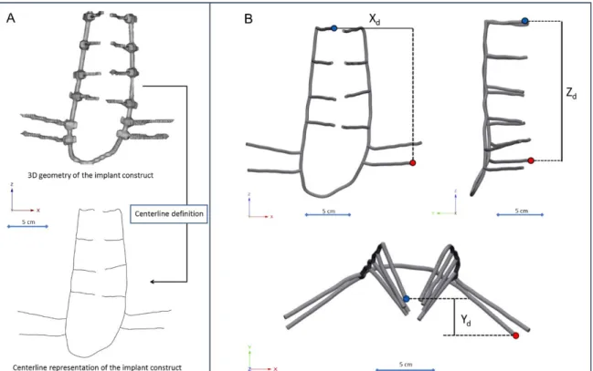
3.3.6. Implant deformity measurements
The implant construct geometry was considered a tubular structure and the centreline of the geometry was defined with the Mimics Software (Figure 11A). A „mobile” point corresponding to the L2 right pedicle screw tip and a fix point was selected in the centreline corresponding to the tip of the caudal iliac screw. The distances between the point were measured in three anatomical planes (Figure 11B, C, D) using 3-matic® software (Mimics Innovation Suite v21.0, Materialise, Leuven, Belgium). The segmentation of the implant construct, the centreline definition and the distance measurement in the three planes were performed by three investigators (I1, I2, I3) a two different time points (T1, T2). For the repeatability and reliability test of the measurements from the Xd (coronal plane), Yd (axial plane), Zd (sagittal plane) the three dimensional distance 3Dd was calculated using the formula 3Dd=�𝑋𝑋𝑑𝑑2+𝑌𝑌𝑑𝑑2+𝑍𝑍𝑑𝑑2
Figure 11. Implant construct geometry simplification and deformation measurement. A the segmented geometry of the implant construct was considered a tubular structure, the centerline of the geometry was defined. B, C, D a fix point (red dot) was selected in the centerline corresponding to the tip of the caudal trans iliac screw, and a mobile point (blue dot) corresponding to the L2 right pedicle screw tip. The distance between the point were determined B in the coronal plane ( Xd), C sagittal plane (Zd), D axial plane (Yd)
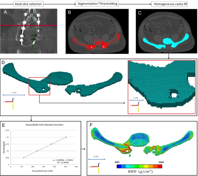
3.3.7. Mapping of the bony fusion
In every CT scan, from the same region of interest (midplane between the right LIV and LV pedicle screw) a single axial slice was selected (Figure 12A). The bone tissue was segmented based on thresholding algorithm, to determine the outer boundary of the bony element (left
where selected with the same acquisition protocol and machine (Table 3). The date of the scans where selected to be in the same month as the postop CT scans. The male subjects also had to have similar body mass index (BMI=28±2) as the presented patient (BMI=28). The Hounsfield Units values of the QCT images were converted into BMD equivalent values by using a densitometric calibration obtained with an inline phantom (HitachiPresto,Hitachi Medical Corporation,Tokyo, Japan) with five cylindrical insertion with known mean equivalent BMD values (0, 0.5, 0.1, 0.15, and 0.2g/cm3). Based on the 12 QCT a mean conversion curve was defined and assumed to be linear (BMD=ρQCT=a+b*HU, where ρQCT [g/cm3] is bone density) according to studies [9,10]. Figure 12E. In the voxel-based FE mesh every element was coded with 10 different colour code corresponding to the BMD values as shown in Figure 12F. The distribution of the FE nesh voxel element over the FU was analysed. The volume of the BMD categories were calculated (voxel dimension*number of elements) and visualised using a 3D surface plot (Figure 38) created with SigmaPlot 12 (SSI, San Jose, California, United States).
3.3.8. Statistical analysis
All statistical tests were performed with SPSS statistical package version 23 (SPSS Inc, Chicago, IL). Due to the small sample size we used non-parametric tests. Inter-rater (I1 vs I2
vs I3) reliability was determined by Intraclass Correlation Coefficient (ICC) estimates and their 95% confident intervals (CI) were calculated based on a mean-rating (k = 2), absolute- agreement, 2-way mixed-effects model. Intra-rater (I1T1 vs I1T2, I2T1 vs I2T2, I2T1 vs I2T2) reliability was determined by ICC estimates and their 95% confident intervals were calculated based on a single measurement, absolute-agreement, 2-way mixed-effects model.
The relationships between the implant deformation in the anatomical planes and the number of postop days were analysed by the Spearman's rank correlation (Figure 36).
Figure 12. Evaluation of the bony fusion process between the LV vertebra and the two iliac bone. A from all the 12 CT scans, form the same region of interest (midplane between the right LIV and LV pedicle screw) an axial slice were selected. B the bone elements were segmented in the slice. C a homogeneous mask was crated corresponding to the bony element. D a voxel-based FE mesh was created based on the segmented mask. E a linear relationship was used to assign the bone mineral density values for the corresponding Hounsfield values. F in the voxel-based FE mesh every voxel was coded with a color code corresponding to the BMD.
3.4. PART IV. Application of 3D printing in spine care 3.4.1 Definition of the 3D geometry
A CT scan of a lumbar fourth (LIV) vertebra of a 25-year-old patient was selected from a study of 270 patients who underwent different treatments due to low back pain in our clinic (MySPINE, Project ID: 269909, Funded under: FP7-ICT). The vertebra of our interest and the neighboring segments were not affected by any musculoskeletal pathology. In order to define the 3D geometry, we performed thresholding and manual segmentation in 3D Slicer 4.1.1 [81], an open-source, free software: http://www.slicer.org (Figure 13).
Figure 13. Definition of virtual 3D geometry from 2D medical images. During the segmentation process the bone volume is first separated from the surrounding soft tissue by thresholding of the greyscale levels of the CT images. The resulting mask (yellow) voxels represent the 3D volume of the vertebra. Then, from the mask, a triangulated surface mesh is automatically generated and exported into in STL (STereoLithography) format.
Before 3D printing the quality of the 3D surface mesh is adjusted (remesh), while preserving the geometrical accuracy. The final vertebra model (FVM) is built from 8024 vertices and 16048 triangulated faces.
To evaluate the accuracy of the segmentation process, we calculated the Dice Similarity Index (DSI) with 3D Slicer Dice-Computation tool [76], for the DSI definition see methods: 3.2.2. Definition of pre- and postop motion segments’ 3D geometry. The DSI values range between 0 ± 1, one denoting a perfect match. DSI value of the segmentation process was 0.96 indicating a high accuracy.
3.4.2 3D printing
The segmented geometry was converted to STereoLithography (STL) format using the “ModelMaker” module of 3D Slicer. Inspection and correction of the 3D geometry was performed with MeshLab1.3.2 [77] (an open-source free software: http://www.meshlab.net), and the following adjustments were made on the triangulated surface mesh: (1) isolated pieces were considered artefacts and therefore, were removed; (2) duplicate edges and faces, that resulted from unification were deleted; (3) universal remeshing with contour preservation. A final vertebra model (FVM) was built from 8024 vertices and 16048 triangulated faces (Figure 13.).
The FVM was printed with the following two 3D printing technologies: (1) Fused Deposition Modelling (FDM) device (Dimension 1200es 3D Printer; Stratasys, Israel) Figure 14A, in which a thin filament of plastic (ABSplus in ivory) is melted in an extruding head, which is then deposited to build the desired shape, slice by slice, on a moving platform.
During the printing all the significantly protruding parts are supported by a concurrently printed scaffold (printed from a water-soluble plastic; Soluble Support Technology, SST).
The internal grid structure of the model (Figure 14C) is automatically generated. The building size of the machine is 254 x 254 x 305 mm and operates with a layer thickness of 0.330-0.254 mm. (2) The Digital Light Processing (DLP) device (VOXEL L 3D Printer;
Do3D, Hungary) polymerizes selectively illuminated planes of the model, slice by slice (Figure 14 B). The DLP uses a model material Voxeltek White Resin (photo-polymer, acrylic based), and a light emitting diode (LED; with ultraviolet spectrum) as a light source.