DOI: 10.1556/606.2020.15.2.18 Vol. 15, No. 2, pp. 199–210 (2020) www.akademiai.com
OPTIMIZED ROOM ARRANGEMENT AND BUILDING SHAPING OF AN INDUSTRIAL AND
OFFICE FACILITY
1 Tamás ANDROSICS*, 2 Bálint BARANYAI
1 Marcel Breuer Doctoral School, Institute of Architecture, Faculty of Engineering and Information Technology, University of Pécs, Boszorkány u. 2, H-7624 Pécs, Hungary
e-mail: tamasandrosics@gmail.com
2 Department of Building Structures and Energy Design, Institute of Architecture Faculty of Engineering and Information Technology, Boszorkány u. 2 and János Szentágothai Research Center, Ifjúság u. 20, University of Pécs
H-7624 Pécs, Hungary, e-mail:balint.baranyai@mik.pte.hu
Received 12 March 2019; accepted 13 November 2019
Abstract: This paper proposes the application of energy efficient, low tech (passive) building design strategies and concepts in an industrial facility case study, in order to create a building with high efficiency and comfort within the boundaries of a tight investment cost. The planning process is supported by dynamic thermal and daylight simulations. Two versions were considered, a conventional industry building and a low tech one with climate zone based space organization. According to the evaluation of thermal and visual comfort as well as energy demand the selected version with the innovative passive concept delivered considerably better performance.
Keywords: Vernacular architecture, Climate zoning, Daylight, Thermal simulation, Indoor climate and energy, Radiation, Thermal comfort, Energy demand, Venturi roof
1. Introduction
Recently, there is a huge increase on demand of energy efficient industrial and office establishments at global level in the industrial. At the international level, Europe’s one of the largest zero-emission plant ‘Solvis’ in Braunschweig [1], the workshops and offices in Lindenberg [2], the solar factory in Freiburg, or the SMA Solar Technology AG factory, which produces solar energy inverters and possesses a CO2-neutral production, can be traced. A prominent model in Hungary is the production hall and office building of Rati Ltd. [3] in Komló, which was erected in 2012. The realized
* Corresponding Author
industrial and office establishment is one of the most outstanding examples of building development in Hungary [4]. A further project at the University of Pécs, Faculty of Engineering and Information Technology represents an innovative modification alternative of the passively ventilated technology hall. By the planning of the new facility located in Marcali, the energy design method was applied; including thermal dynamic building simulations, vernacular passive principals, building physics based space organization (thermal zones) as well as daylighting concept. During the sketch plan stage, high level of comfort and energy efficiency was kept in mind. On the other side, the contractor sees the industrial hall established in Füzesabony in 2017 as a model for the new facility. Besides keeping the expenses at low level, further expectation was the application of materials analogue to the Füzesabony reference building consisting of standard sandwich panels, PolyVinyl Chloride (PVC) fenestration frames, indoor lightweight gypsum board walls and suspended ceiling, conventional concrete steel structure).
According to the constructor’s concept, the reference building had to be placed by minimal adaptation on the new site. After considering and calling this concept into question, a new ‘energy design’ concept was elaborated at the sketch planning level.
The new concept was compared with the reference building and a quantified, simulation assisted evaluation was provided about the cases. Since there was an essential improvement in comfort and energy level and, in addition, at architectural standard, the constructor could have been convinced to accept the new concept.
2. Building concept creation - climate zoning
After mapping the area according to room planning, the next phase included the horizontal and vertical space organization, to arrange the spaces in thermal zones, based on energy design method [5], [6].
The basic climate zoning concept applies a vernacular principle of the wraparound a traditional farmhouse or shepherd’s nest in a cold cool dry or cold wet climate of the Alps [7]. Fig. 1 demonstrates the heated living central space surrounded by a stall,which is an unconditioned climate zone. The animals’ metabolic heat dissipation tempers the house, creating a ‘thermal buffer’ zone as thermal insulation skin against transmission loss. The houses are generally oriented south/southwest. The concept of the new industrial facility is based on this vernacular method. The greatest heated work space represents the workshop hall, which is surrounded by further spaces from 3 sites (north, east and west). In this way the workshop is intensively protected from winter transmission heat losses and against summer heat loads. The east and west sides are particularly disadvantageous in office and industrial installations during the summer cooling periods, as the solar load may increase up to 100% relative to a southern orientation, depending on the façade glazing ratio design [8]. From these sides (east and west), so-called ‘buffer zones’, the storage hall, the oil depot and the component/part warehouse protect the workshop hall without fenestration in their façades. From the north side, the workshop is protected by the office section that is optimally oriented to the north, in order to reduce solar loads in summer.
Fig.2 shows the space and climate zoning system of the building realized in Marcali.
The office unit is linked from north to the workshop hall, although the office section does not function as a buffer itself, rather it is a ‘sheltering zone’ with highest standard of comfort. The northern orientation of the office partition is advantageous due to the high diffuse radiation ratio of solar radiation (low direct radiation), therefore the heat load can remain low in these rooms.
Fig. 1. Vernacular architecture principal in the Alps
Fig. 2. Location of thermal zones of the sketch plan, top floor (above), 1st floor (in the middle), realized building in Marcali, main entrance (bottom)
Basically, office spaces require a high summer cooling demand, due to the high internal heat production (large number of occupants, equipment and lighting) and solar radiation heat load, generating high running costs. The workshop hall is equipped only on the south side of the building body with an external façade surface, from which solar
thermal gains can be utilized through the transparent doors and windows during the winter heating operation. The south façade of the workshop hall possesses 25 % Wall Window Ratio (WWR) to ensure winter solar heat gains and daylighting in the south part of the hall. East and west façade of the warehoses are opaque walls for minimizing solar loads in summer. Workshop and warehouse space have an approx. height of 7.0 m, hence the office section is connected with its entire internal wall surface to the workshop and warehouses in a 2-storey design, as an economical and reasonable solution. In this way, the workshop received full thermal protection from all directions except the southern side along the façade (natural ventilation, daylighting and heat gain purposes). The roof structure is a low-angle surface, highlighting the appearance of the building’s ‘box’-like character. This roof geometry is also beneficial, otherwise, due to higher roof slope, the built-in heated and cooled volume would increase significantly.
Contractor’s requirement was to keep as much structural and material properties as possible comparable in the two projects. Therefore, building envelope structures, windows and doors as well as Window/Wall-ratio (W/W-ratio) (Table I), and as an effect, the average thermal transmission coefficient remained as analogue as possible, according to the building concepts. The W/W-ratio is slightly changed due to the new functional room organization. The Area/Volume-ratio A/V-ratio of the new design is lower due to optimized space and climate zone organization and building body shaping (box-like form). The reference building possesses 0.509 m2/m3, while the new building’s A/V-ratio delivers 0.433 m2/m3, meaning 15% optimization of the ‘heat loss surface - heated volume ratio’ (Fig. 3, Table I). Utilizing the maximal possibilities of the building structure, a thermal activated reinforced concrete fundament-slab of 20 cm thickness was integrated to control the workshop hall’s interior thermal comfort due to its thermal mass, as well as to assure adequate base for the heavy equipment [9].
Fig. 3. Existing reference project: Füzesabony building 3D thermal model (left), New project:
Marcali building 3D thermal model (right)
Table I
Existing reference project and new project building thermal model data Model ’Füzesabony’ Model ’Marcali’
Volume (m3) 5007.5 m3 5400.4 m3
W/W-ratio (%) 3.7 % 5.0 %
A/V-ratio (m2/m3) 0.509 m2/m3 0.433 m2/m3
The workshop space has a square geometry of approx. 19.0x18.7 m that is advantageous for the A/V-ratio, but at the same time disadvantage occurs due to the large depth of the interior. Thus the natural ventilation and illumination is problematic
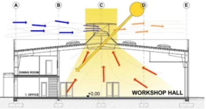
in the space far from the external façade. Solving this, a Venturi wind draft accelerator is applied to serve as passive (natural) ventilation and as a skylight roof structure [10], [11].
The roof structure is made of clear polycarbonate to provide diffuse daylighting in under-illuminated rear zones in the workshop (Fig. 4). The illumination, provided by the skylight roof windows is a high-efficient solution, since from the top approx. 5 to 10 times greater amount of daylight can enter the interior, compared to same sized side façade openings.
Fig. 4. Natural ventilation and lighting concept - cross section (A-A) of the new ‘Marcali’
industrial and office facility
3. Comfort and energy performance results
A comparative analysis was carried out between the existing and the new establishment. The thermal building models were created by the help of IDA ICE 4.8 software, considering the thermal comfort and energy performance. The local weather profile was assured by METEONORM 7 software. Based on measurements in multiple weather stations (8 000 weather stations, five geostationary satellites and a globally calibrated aerosol climatology), the global climate database METEONORM generates accurate and representative hourly based yearly climate values (more than 30 different weather parameters) for any place on earth. On this basis, sophisticated interpolation models, based on more than 30 years of experience, provide results with high accuracy worldwide. Because of some marginal changes in the project dimensions (request from contractor), the energy results were evaluated in kWh/m2 net floor space.
In particular sketch plan stage a simplified dynamic thermal simulation modeling method was applied. This approach requires significantly shorter calculation time effort, while ensuring appropriate results for the purpose of comparative analysis of sketch plan building design variations. In this project stage space organization, building body shaping, W/W-ratio orientation and integration into site (surroundings, neighborhood) with shading effects are to be quantified and compared in different concept versions.
The boundary conditions and settings are simplified according to sketch plan design detail level: The models are equipped with simplified theoretical heating and cooling systems (‘ideal heater and cooler’) without specified plant model (Coefficient Of Performance/Energy Efficiency Ratio COP/EER=1). Reasonable sized heating and
cooling power was applied with 100 W/m2 heating and 200 W/m2 cooling power. The rooms are operated without window ventilation; rather an industrial standard Air Handling Unit (AHU) system provides appropriate Air CHange (ACH) of 2 l/m2s. Set- points for heating 21 C° and for cooling 23 C° are defined, beside an infiltration value of 4 ACH at 50 Pa pressure difference, since the building is constructed from prefabricated sandwich panels, which typically provide less air tightness. Occupants are modeled according to the contractor’s information; lighting and equipment are handled according to standard conditions. The workshop hall is the most decisive space in the building, where 8 men work daily. In the offices usually 1-2 occupants work in a day.
Artificial lighting is edited with 0.1 lamp unit/m2 with 100 W rated inputs per unit and 12 lm/W luminous efficacies. Equipment emits 75 W heat/units with the following installation: 1-2 pieces in offices, 2 pieces in the workshop, 1 piece in meeting room and 2 pieces of equipment in the shop. The operation of lighting, equipment and occupants is scheduled for 7:00 - 18:00 every workday. Since occupants’ behavior can decisively influence energy efficiency [12], related control programing can be useful in future research.
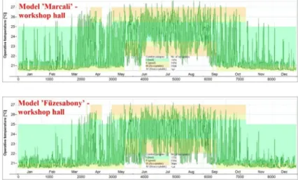
Thermal comfort values are to be analyzed firstly, to ensure most important and appropriate conditions for the indoor environment. In comparison of the two projects, the classification of the operative temperature hours delivers better performance in the new building. In a sample office at the west corner of the building (with west and north oriented façades and windows) 43% more comfort hours are performed in occupation duration time in the best (I) category according to EN 15251 [13] (Fig. 5). Reason for the overheating of the Model ’Füzesabony’ office are the additional east and west oriented façades of the office section, gaining more solar loads in the interior. The workshop halls show nearby analogue comfort characteristics (Fig. 6).
Fig. 5. ‘Füzesabony Office 1’ operative temperatures according to EN 15251, 8760 h resolution (above), ‘Marcali office 1’ (bottom)
Although the fenestration ratio is nearly the same in both halls, due to the 315%
greater window area in the south façades and the 55.2 m2 skylight in the roof, the Model
’Marcali’ receives 54% higher solar (direct and diffuse) radiation load in passive and cooling season (in Hungary: April 15 - October 15).
Fig. 6. Füzesabony Workshop hall operative temperatures according to EN 15251, 8760 h resolution (above), ‘Marcali Workshop hall’ (bottom)
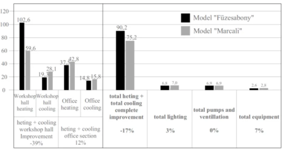
The used energy demand is relevant to assess in the framework of the sketch plan design stage investigations. The various energy demands of lighting, equipment, mechanical ventilation (only ventilator demand), heating and cooling were calculated in kWh/m2a. Each energy demand value is multiplied with the according used floor space that is relevant to the heated, cooled, lighted, etc. spaces. The different buildings show significant deviation in heating and cooling demand. While the thermal energy need of the rooms were evaluated based on sensible thermal energy balances, the whole building related used energy demand is calculated as sensible and latent used energy.
Pumps, ventilation and equipment energy demand is accounted as final energy (electricity).
Pumps, ventilation and equipment‚ behave’ similarly in the models, since the settings and boundary conditions were same or very similar as well. Despite the different room and window orientation arrangements in the model variations, lighting final energy demand remained approx. the same in both models. Reason for that is the same W/W-ratio in the two models and the different sized and oriented windows, which generate - as an end-result - approx. similar artificial lighting electricity demand.
The heating-cooling energy demand of Marcali workshop hall is far lower than the reference workshop (Fig. 7). The Marcali workshop hall’s (363.1 m2) energy demand is 87.68 kWh/m2, while the other workshop’s (339.6 m2) energy demand is much higher 121.99 kWh/m2, indicating 39% energy saving. Reason for the 61% lower heating demand in model ’Marcali’ workshop hall is the 65% fewer external wall surface (33%
lower heat loss from transmission and thermal bridges), the 35% greater solar gain
(Fig. 8) during operation time period (September 15 - May 15, 4886.3 h), and the 3249% higher infiltration losses (in Füzesabony workshop) through the external building envelope joints.
Reason for the 56% higher cooling demand in model ’Marcali’ workshop hall is provided by the 54% solar loads during transition and cooling operation time period (in Hungary: March 15 - October 15, 2516.3 h) (Fig. 8).
Fig. 7. Mechanical ventilation and simplified (ideal) space heating and cooling used thermal energy demand [W] in the different Models; model ’Füzesabony’ (left); model ’Marcali’ (right)
Fig. 8. Global solar radiation load, 8760 h resolution [W] in the workshop hall in the different simulation models
The heating and cooling demand of the new building’s office block (275.55 m2) amounts 58.63 kWh/m2a, while the Füzesabony office block’s (285.93 m2) demand is 52.33 kWh/m2 that indicates 12% disadvantage compared to the reference building. The 10% heating increase by model ‘Marcali’ office block had been evolved due to higher, interior spaces and east west oriented glazed façades, as well as the bigger sized fenestration. The 12% higher cooling demand in Marcali office block was emerged by 14% higher W/W-ratio, as well as the two-storied design (upstairs spaces are warmer).
Furthermore the 2 corner offices in model ‘Füzesabony’ have bigger exterior façade heat loss surfaces.
Analyzing the total heating and cooling energy demand of the complete buildings, 17% (Fig. 9) conservation (15 kWh/m2) could be reached in model ‘Marcali’, as an effect of the following passive design strategies:
• Innovative climate zoning (space organization) based on vernacular passive strategy, workshop is protected against heat loss by surrounding building parts;
• More efficient building body shape with better (15% lower) A/V-ratio, heat loss surface;
• More advantageous orientation of the spaces, workshop is south oriented, offices are north oriented.
Fig. 9. Used energy demand (kWh/m2a) in different systems
4. Daylight optimization of the workshop storage halls
Further, the daylight quality of the workshop needed to be increased in the rear part of the hall, where weak daylight illumination prevails, due to large distance from the south façade. Daylight Factor (DF) [14] simulations were carried out using mixed, diffuse sky model International Commission on Illumination (ICI overcast sky) and RadianceTM calculation solver. The evaluation should help making decision about a roof integrated skylight structure in the workshop, above the rear, under-illuminated zone.
The workshop hall performs an average of DF 1.02 without skylight, hence an a unacceptable level of visual comfort (Fig. 10, left). A large sized skylight and Venturi’
ventilation structure of 87 m2 roof opening [15], [16] enabled reaching an average daylight factor (Dave) value of 3.42 (Fig. 10, middle), while a so-called ‘cost- optimized’, smaller skylight structure (55.2 m2 opening) provides an average DF of 2.71 (Fig. 10, right). This solution was considered as a reasonable compromise-optimum between visual comfort and cost-efficiency, by supplying a DF over 2 in approx. 63.2%
of the net floor space. This version was selected for implementation as well.
The storage areas needed also skylights, but here for other reasons: the wall surfaces of the storage optimally provide areas for shelves, therefore openings, doors and windows are not advantageous for integration alongside the walls. The storage area skylights are simpler structures, integrated in the roof surface in-plane for natural lighting and ventilation. In this case two versions were compared, testing smaller and
larger sizes, 1.5 x 1.5 m and 2.0 x 2.0 m, respectively. The smaller skylight version (Fig. 11, left) represents a minimum provision of natural lighting, while the larger skylight version (Fig. 11, right) possesses additionally more daylight delivery, as an advanced version. The obviously higher DF results of the advanced version enable significantly higher level of luminance between 1 and 2% - values appropriate for storages. This version was selected for further construction.
Fig. 10. Without skylight DF average: 1.02,(left); cost optimized skylight with 55.2 m2 opening DF average: 2.71(middle); large skylight with 87 m2 opening DF average: 3.42 (right)
Fig. 11. Small skylight 1.5 m/1.5 m; DFaverage west storage: 0.84; DF average east storage: 0.89;
DF average tool storage: 0.57 (left). Optimized skylight 2.0 m/2.0 m; DF west storage: 1.48; DF average east storage: 1.49; DF average tool storage: 1.03 (right)
The study results were finally processed in further final planning stage to prepare the construction. 2017, the implemented building shown in Fig. 12 was set into operation.
Fig. 12. Realized building in Marcali, main entrance
5. Conclusion
The completed thermal dynamic simulations and the adaptation of Energia Design method confirmed the new building concept in the sketch plan stage. Regarding thermal comfort it can be assessed that the new hall and office building in Marcali performs in the sample office significantly (43%) increased number of comfort hours, compared to the thermal comfort performance of the reference building in Füzesabony. The thermal comfort of the workshop halls does not significantly differ from each other. However, the new workshop hall shows rather beneficial results for heating and natural illumination. The total heat (heating and cooling) used energy demand of the new complete building achieves 17% energy saving due to space organization based on thermal zones, optimal building shape (A/V-ratio) and advantageous space orientation.
In addition, the visual comfort quality was optimized applying skylights, due to that the daylight factor increased to 166%. The skylight also maintains the problem of ventilation, assisting the air-change of the rear zone that cannot be ventilated in natural way. In the sketch plan phase a terminated number of conceptions could be tested and analyzed, since architectural projects typically possess strictly limited timeframes.
Compared to conventional architectural and engineering planning, the applied energy design method reveals significantly higher comfort and energy performance results. On the other hand, this solution do not include all possible cases, therefore it cannot ensure the optimal design solution. For that purpose development of a combined architectural, building physics and mathematical method is required.
Acknowledgements
This research was carried out with support of the University of Pecs, János Szentágothai Research Centre, the Kistelegdi 2008 Architecture Design Ltd, and the Energia Design Planning, Development and Consulting Spin-off Ltd.
Open Access statement
This is an open-access article distributed under the terms of the Creative Commons Attribution 4.0 International License (https://creativecommons.org/licenses/by/4.0/), which permits unrestricted use, distribution, and reproduction in any medium, provided the original author and source are credited, a link to the CC License is provided, and changes - if any - are indicated. (SID_1)
Reference
[1] Jäger H. Solvis zero-emission factory - The ‘Solvis way’ - Structure and subject, Glocalized solutions for sustainability in manufacturing, Hesselbach J., Herrmann C. (Eds.) Springer, 2011, pp. 29‒31.
[2] Hausladen G., Tichelmann K., Interiors construction manual: Integrated planning, finishings and fittig-out technical services, Munchen, 2010.
[3] Tian Jin. World classic ecological architecture, Phonix Publishing, China, 2012.
[4] Reith A. Thoughts Hungarys first energy positive industrial production plant (in Hungarian), Metszet: Építészet Újdonságok Szerkezetek Részletek, Vol. 6, 2012, pp. 56‒57.
[5] Baranyai B., Póth B., Kistelegdi I. Planning and research of smart buildings and constructions with the ‘Energydesign Roadmap’ method, Pollack Periodica, Vol. 8, No. 3, 2013, pp. 15‒26.
[6] Kistelegdi I. Plus energy potential in an industrial and office building, (in Hungarian), University of Pécs, Faculty of Engineering and Information Technology, Hungary, 2013.
[7] Behling S., Behling S., Schindler B., Foster N. Solar Power, (in Spanish) Ediciones Gustavo Gili, 2000.
[8] Hausladen G., de Saldanha M., Liedl P. Climateskin : building-skin concepts that can do more with less energy, Springer, 2007.
[9] Friembichler F., Handler S., Krec K., Kuster K. Energy-storage concrete: thermal component activation, Bundesministerium für Verkehr, Innovation und Technologie, Wien, 2017.
[10] Van Hooff T., Blockena B., Aanenc L., Bronsemad B. Numerical analysis of the performance of a venturi-shaped roof for natural ventilation: Influence of building width, Journal of Wind Engineering and Industrial Aerodynamics, Vol. 104-106, 2012, pp. 419‒427.
[11] T. Herzog, Wind Tunel Test, Verlag Gerd Hajte, Design Center Linz, Ostfildern-Stuttgart, pp. 114-119, 1994
[12] Reith A., Belafi Zs. Interdisciplinary survey to investigate energy-related occupant behavior in offices - the Hungarian case, Pollack Periodica, Vol. 13, No. 3, 2018, pp. 41‒52.
[13] Indoor environmental input parameters for design and assessment of energy performance of buildings addressing indoor air quality, thermal environment, lighting and acoustics, https://www.en-standard.eu/din-en-15251-indoor-environmental-input-parameters-for- design-and-assessment-of-energy-performance-of-buildings-addressing-indoor-air-quality- thermal-environment-lighting-and-acoustics/ (last visited 3 April 2019).
[14] Daylight factor, https://patternguide.advancedbuildings.net/using-this-guide/analysis- methods/daylight-factor, (last visited 7 February 2019).
[15] Kistelegdi I., Baranyai B. Wind tunnel investigations to identify and validate the effect of wind induction and thermal buoyancy on the natural ventilation of an industrial innovation center, (in German) Bauphysik, Vol. 34, No. 5, 2012, pp. 229‒237.
[16] Kistelegdi I., Haber I. Building aerodynamic investigations of a plus energy production plant with passive ventilation Towers in Sikonda (Southern Hungary), (in German) Bauphysik, Vol. 34, No. 3, 2012, pp. 107‒120.


![Fig. 8. Global solar radiation load, 8760 h resolution [W] in the workshop hall in the different simulation models](https://thumb-eu.123doks.com/thumbv2/9dokorg/769497.34199/8.892.267.689.531.689/global-solar-radiation-resolution-workshop-different-simulation-models.webp)