A R T I C L E
Shear-aided high-throughput electrospinning: A needleless method with enhanced jet formation
Yahya Kara
1| Haijun He
1| Kolos Molnár
1,21Budapest University of Technology and Economics, Faculty of Mechanical Engineering, Department of Polymer Engineering, Budapest, Hungary
2MTA–BME Research Group for Composite Science and Technology, Budapest, Hungary
Correspondence
Kolos Molnár, Budapest University of Technology and Economics, Faculty of Mechanical Engineering, Department of Polymer Engineering, Budapest, Hungary.
Email: molnar@pt.bme.hu
Funding information
Emberi Eroforrások Minisztériuma, Grant/Award Number: BME FIKP- NANO; Magyar Tudományos Akadémia Számítástechnikai és Automatizálási Kutatóintézet, Grant/Award Number: FK 131882; Nemzeti Kutatási Fejlesztési és Innovációs Hivatal, Grant/Award Number: ÚNKP-19-4; Nemzeti Kutatási, Fejlesztési és Innovaciós Alap, Grant/
Award Number: K116070; Hungarian Academy of Sciences; China Scholarship Council, Grant/Award Number:
201700500073; Tempus Közalapítvány;
Budapest University of Technology and Economics; Ministry of Human Capacities
Abstract
In this article, we introduce a novel high productivity electrospinning setup for scaling up the classical method. We propose a new spinneret concept, which allows the shearing of the polymer solution prior to electrospinning. Most of the solutions used in electrospinning are shear-thinning, that is, as they are sheared, they show smaller resistance against the deformations caused by the electrostatic field. Therefore, enhanced Taylor-cone formation can be achieved, and it also gives a hand in controlling the nanofiber morphology easily, even during operation. In this study, we investigated the influence of shearing on the electrospinning process and the fiber morphology. When shearing was applied by rotation, the operation became more stable and the fiber morphol- ogy improved. Multiple jets were observed along the circular edges of the spin- neret, also became thinner as an effect of the shearing rotation. The average diameter of the electrospun nanofibers was decreased by 18% with rotation speed applied, compared to those of the nonrotating condition (0 rpm). Besides that, we found that the electrospun nanofiber diameter distribution was signif- icantly different for the various rotation speeds for which we found an applica- ble explanation with the aid of high-speed camera recordings.
K E Y W O R D S
biomaterials, needleless electrospinning, fibers, morphology, rheology
1
|I N T R O D U C T I O N
Electrospinning has become a very important nanofiber processing technology because of its versatility: a wide range of applicable polymers in producing nanofibers, with controllable fiber diameter and morphology exist.
The main features of nonwoven nanofiber mats produced by electrospinning are the high surface area to volume ratio, the high porosity, the molecular orientation, the
fair tensile behavior, and the excellent flexural properties.[1,2]
Electrospun nanofibers have a great potential in a wide variety of applications including filtration, scaffolds for tissue engineering, drug delivery, superhydrophobic membranes, wound dressing, protective clothing, reinforced composite materials, and micro/nano sensors and actuators.[3–9] In recent years, research interest on electrospinning has shifted from laboratory scales to
DOI: 10.1002/app.49104
This is an open access article under the terms of the Creative Commons Attribution License, which permits use, distribution and reproduction in any medium, provided the original work is properly cited.
© 2020 The Authors.Journal of Applied Polymer Sciencepublished by Wiley Periodicals, Inc.
J Appl Polym Sci.2020;e49104. wileyonlinelibrary.com/journal/app 1 of 13
https://doi.org/10.1002/app.49104
industrial applications.[10] Electrospinning stretches a polymer solution into filament fibers by a high electric field. In the conventional electrospinning method, the solution is supplied from a capillary needle (spinneret) that is charged. The fibers are collected on the counter- electrode surface (collector) in the form of the non- oriented nonwoven web in most cases.[11] Operation parameters are quite important since they greatly affect the quality of the end product. These parameters can be divided into three main groups, which are solution prop- erties, process parameters, and ambient conditions.[12]In many aspects, the solution viscosity (mainly via concen- tration or temperature) is considered to be the dominant factor in determining the fiber diameter. The composi- tion, such as the polymer type, the concentration, the sol- vent used, and the additives (e.g., salt, nanoparticles, etc.) influence the rheological characteristics of the solu- tion.[13,14] At low viscosities, solution surface tension dominates fiber morphology and below a certain viscosity level (i.e., corresponding concentration) droplets are formed instead of fibers.[1,12] Besides, the beaded fiber formation is a common defect observed below a certain level of solution concentration and corresponding viscos- ity.[1,10,12]On the other hand, high viscosity would result in a large fiber diameter.[15]Besides this, several research groups reported that higher electrospinning temperatures can reduce solution viscosity, which leads to the genera- tion of fibers with uniform and small diameter when highly viscous polymer solutions are used.[16–19]
The electrospinning process relies on the phenome- non of uniaxial stretching of a charged jet. The stretching of the charged jet is influenced by the changing viscosity of the polymer solution. When a polymer solution is forced through a capillary, the polymeric fluid generally moves faster near the capillary's axis and slower near its wall[20]; hence, shear stresses are generated, which can change the solution viscosity in the case of non- Newtonian fluid. Therefore, the spinneret or needle gap size influences the rheological characteristics of the electrospinning solution.[21] Besides, the gap size deter- mines the force required for the Taylor-cone formation by changing the diameter of the droplet. In theory, using a small capillary outlet results in the formation of a small droplet of the polymer solution with high surface tension in comparison with large capillaries.[22]
The production of nanofibers through capillaries (needles) is not an efficient way to scale up the electrospinning process, since the field of the capillaries negatively interfere with one another. Although electrospun nanofibers show great potential in different application areas, the poor production rate of the needles hinders the industrialization.[23,24]To overcome this issue, it turned out that besides the capillary method the polymer jets can be
ejected from an open solution surface, which technology is called needleless electrospinning.[25]
Needleless electrospinning technique first patented by Simm et al.,[26]in 1979 on using rings to electrospun fibers for filtration applications. A magnetic field assisted needleless electrospinning was investigated by Yarin and Zussman[24]in 2004. In their study, the initiation of poly- mer jets was aided by a magnetic field to induce the forma- tion of spikes on the solution surface. Liu and He[27]
invented a gas-assisted high-throughput needleless electrospinning method in which jet initiation takes place from gas-filled solution bubbles formed on an open liquid surface. In this method, the number of bubbles, the bubble size, and the applied voltage strongly influence the number of jets. Recently, needleless electrospinning systems using a rotating spinneret have attracted a great attention of researchers. Jirsak et al.,[28] patented a needleless electrospinning method, which uses a rotating horizontal cylinder as the spinneret for the mass production of nanofibers. This unique spinneret and its setup were then rapidly commercialized by Elmarco (Liberec, Czech Republic), under the brand name Nanospider, in 2005.
The design of the spinneret or fiber generator plays a cru- cial role in the generation of polymer jets and thereupon the quality of fibers and productivity. Wang et al.,[23]inves- tigated another high throughput nanofiber making method using a conical wire coil as spinneret. In this setup, the aid of gravity and coil geometry was used to con- vey the polymer solution to the spinning sites. This needleless electrospinning system produces thinner nanofibers on a much larger scale in comparison with the needle-based systems, and the applied voltage highly influ- ences the jet formation and fiber quality. Molnar and Nagy[10] invented a needleless electrospinning spinneret which consists of a long circular channel surrounded by a sharp-edged metal electrode from the outside. In their study, high-quality nanofibers were obtained due to the higher electric field formed close to the spinneret, which supports the formation of self-organizing Taylor-cones.
Besides these methods, a centrifugal electrospinning sys- tem was patented by Andrady et al.,[29]where fiber forma- tion mainly depends on the centrifugal forces rather than electric ones. Here, the applied centrifugal force overcomes the surface tension of the liquid to initiate jets, and the electric field directs and stretches the jets towards the col- lector. Up to date, various rotating and moving spinneret and/or fiber generators, such as ring coil,[30] splashing,[31]
stepped pyramid,[32] disc,[33]ball,[34]beaded chain,[35] spi- ral coil,[36] yarn spinneret[37] and wire[38] for needleless electrospinning were reported for the generation of nanofibers from solutions and melts.
One important obstacle of the mentioned needleless methods is the existence of the large open surface which
can cause contamination of the polymer solution, water vapor absorption, excessive solvent evaporation, and so forth. Besides, there is no detailed report found in the lit- erature manipulating the fiber morphology from the rhe- ological aspect in situ electrospinning. The shear stress applied on the polymer solution influences the viscosity;
therefore, that can give a hand in easily controlling nanofiber morphology by shearing the polymer solution even during the process.
In this article, we investigated a novel method, which utilizes a completely new approach for producing high- throughput nanofiber mats by needleless electrospinning.
Continuous shear deformation is applied to a shear- thinning solution to decrease its viscosity and to enhance jet initiation. The setup includes a spinneret with a rotary inner part with adjustable rotation speed, making possi- ble to control the fiber morphology via the shear (defor- mation) conditions. The simple setup offers continuous operation with high-throughput and moreover issues of fast evaporation, clogging and bead formation are completely avoided. In this study, this new setup and the influence of rotation speed on the fiber morphology are introduced.
2
|E X P E R I M E N T A L 2.1
|Materials
In this study, poly (ethylene oxide) (PEO, Mw = 400,000 g/mol, Sigma Aldrich) was chosen as the model polymer to be electrospun into nanofibers. PEO is widely used for both conventional and needleless electro- spinning due to its nontoxicity and fair water-solubil- ity.[34]The polymer solution with a concentration of 2.5, 3.0, 3.5, 4, 4.5% were prepared in water: ethanol (Vegyszer Kereskedelmi Kft., Hungary) mixture of 3:1 by weight and 0.01% NaCl relative to the mixture was added for achieving better electrical conductivity. The solution was dissolved within a sealed vial by stirring for 24 hr at room temperature by a magnetic stirrer.
2.2
|Rheology experiments
To quantify the viscosity and the shear rate of the PEO solution an AR 2000 type rheometer of TA Instruments was applied in a plate-plate configuration with a gap size of 0.6 mm and an upper plate diameter of 40 mm. Rheol- ogy experiments were performed at setting the lower (fixed) plate temperature to 22.5C. The shear rate (induced by the spindle rotation) was stepped in the range from 1 to 10,000 1/s in 20 points/decade increments.
2.3
|The shear-aided needleless electrospinning setup and parameters
The method and setup (Figure 1) we investigate in this paper has been patented recently.[39] The spinneret manipulates the solution viscosity via the shear rate and shear stress induced by the rotor (2). The solution is pumped through an annular orifice (3) located between the rotor (2) and the stator (1), both having a sharp edge at the outlet. The rotation is provided by the drive shaft (9). At a non-Newtonian fluid, the applied angular veloc- ity (ω) determines the resistance of the polymer solution against the shearing. Thus, the spinneret manipulates the solution parameters by the rotation speed and orifice gap size leading to various fiber morphologies.The setup used (Figure 2) consists of a power supply (1) (MA2000 NT 65/P, Hungary), a syringe pump (2) (Aitecs SEP-10S plus, Lithuania), a collector plate cov- ered with aluminum foil (3), the spinneret (5) and its fixed stand (4), and besides, a high-speed camera (8) was also applied. The applied voltage was set to 35 kV. For all the experiments, the distance from the spinneret to the collector plate was kept 200 mm. The flow rate of the polymer solution was set to 15 ml/h.
F I G U R E 1 Schematic draft of the electrospinning setup; 1:
stator, 2: rotor, 3: annular orifice, 4: fixed stand, 5: high voltage supply, 6: grounded collector screen, 7: solution feed, 8: seal, 9:
drive shaft
The novel spinneret used in the experiments is depicted in Figure 3. The spinneret was fixed onto the stand via three screws (1) and leveled with the aid of a bubble leveler (2). The spinneret stator (3) and rotor (4) had a diameter of 50 and 49 mm, respectively, thus the gap size (width of the annular orifice [5]) was 0.5 mm. The rotation was provided by a D.C. electric motor (fixed to the stand from the inside) connected to the spinneret with a 100 mm long plastic drive shaft. The rotation speed of the electric motor was measured by a tachometer (Xinsite Digital Tachometer, China).
2.4
|Single needle (capillary) electrospinning
Within the scope of this study, single needle electrospinning experiments were performed for compar- ison. We used a blunt needle with an inner diameter of 0.51 mm to compare the results to those obtained by
the needleless setup. Polymer solution concentrations varying between 2.5 and 4.5% were used. The corresponding solution viscosities at zero shear rate obtained by rheometry are given in Table 1. Flow rates of 0.5 ml/h and 1 ml/h were applied for the single needle electrospinning experiments. All other parameters, such as solution, process, and ambient temperature and humidity were kept unchanged. The single needle electrospinning setup schematic is shown in Figure S1.
2.5
|Imaging and processing
The morphology and diameter of the electrospun nanofibers were observed by using scanning electron microscopy (SEM; JEOL 6380 LA, Japan). We pasted nanofiber mats carefully onto metallic studs with double- sided conductive tape. The surface of the nanofiber mat samples was finely coated using JEOL JFC-1200 (Japan) fine coater with gold–palladium (Au-Pd) alloy in order to avoid their charging. Image analysis software (ImageJ 1.51 k) was utilized to measure electrospun nanofiber diameters. We measured 100 fibers for each sample to analyze the electrospun nanofiber diameter distributions.
In order to investigate the Taylor-cone and jet formation, we used a Keyence VW-9000 high-speed camera. We set the camera to 1,000 frames per second (fps) for the investigation of the jet formation. As the depth of field was limited with the standard zoom lens, only the half of the circular orifice was considered. We carried out a quantitative analysis based on the number of forming jets and Taylor-cones.
2.6
|Statistical analysis
We investigated the electrospun nanofiber distributions by using theχ2two-sample test method.[40]In theχ2two sample statistical analysis, the relation between the electrospun nanofiber diameter distributions and the corresponding rotation speeds were investigated. Thep- values less than .05 (level of significance) were consid- ered significantly different. The related test method for F I G U R E 2 Experimental setup of the novel shear-aided
needleless electrospinning; 1: power supply unit, 2: syringe pump, 3: collector screen, 4: fixed stand, 5: spinneret, 6: high voltage cable, 7: grounding cable, 8: high-speed camera [Color figure can be viewed at wileyonlinelibrary.com]
T A B L E 1 The PEO solution concentrations and the corresponding viscosities at zero shear determined by rheometry
Concentration (%) Viscosity (Pa s)
2.5 0.27
3.0 0.50
3.5 0.89
4.0 1.80
4.5 2.70
F I G U R E 3 Shear-aided needleless spinneret; 1: fixing screws, 2: bubble leveler, 3: stator, 4: rotor, 5: annular orifice, 6: cap nut that helps the disassembly [Color figure can be viewed at wileyonlinelibrary.com]
the χ2 two-sample analysis is given in the Supporting Information.
3
|R E S U L T S A N D D I S C U S S I O N 3.1
|Determination of PEO solution viscosity and shear stresses
The results obtained from the viscometry are shown in Figure 4. A clear shear-thinning (pseudoplastic) behavior of the solution can be observed. For the 2.5–4.5% PEO
solutions viscosity and shear stress variation with respect to shear rate for different temperatures are shown in Figure S2–S6.
The relative motion of the rotor and the stator manip- ulates the solution viscosity by shearing that. Therefore, in order to determine the effect of the rotation speed of the spinneret, a systematical analysis of the obtained rheometry results was carried out. We chose eight differ- ent viscosities and corresponding shear rates for the 4.5%
PEO solution which we used for the electrospinning experiments. The shear rates were converted to rotation speeds by using Equation (1).
F I G U R E 4 Variation of viscosity and shear stress of PEO solutions (a) 2.5%, (b) 3%, (c) 3.5%, (d) 4%, (e) 4.5% versus variable shear rates at 25C [Color figure can be viewed at wileyonlinelibrary.com]
Ω= 60hγ_
2πR ð1Þ
where,Ω, h, R,γ_ represent the rotation speed (rpm), the gap size (m), the orifice radius (m), the shear rate (1/s), respectively. The calculated rotation speeds of the spin- neret are given in Table S 1. The deviation of the actual rotation speeds was less than 5 rpm during the electrospinning. Accordingly, the relation between the rotation speeds and the solution viscosity is illustrated in Figure 5.
3.2
|Electrospinning experiments 3.2.1
|Shear-aided needleless electrospinning experiments
After the electrospinning, the fiber morphology was stud- ied by SEM and the fiber diameters were measured by Image J. The average nanofiber diameters and the corresponding rotation speeds are given Table S2.
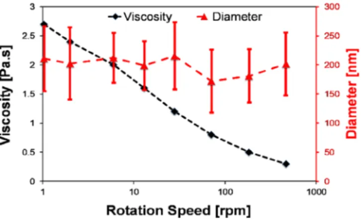
Figure 6 represents the relations between the rotation speed, the average diameter and the viscosity. We depicted the nonrotating spinneret at 1 rpm in the loga- rithmic scale to avoid zero and to take the solution flow speed into account this way. However, there is only a slight change in the average fiber diameters, the applied rotation speed influences the diameter distribution of the electrospun nanofibers.
Only from the average values, it is difficult to under- stand how the rotation speed influences the electrospun fiber diameters and morphology. Therefore, we investi- gated the diameter distributions in detail. The histograms obtained together with corresponding SEM images are presented in Figure 7.
The SEM images of nanofibers of the different rota- tion speeds show different fiber morphology in terms of fiber diameter and shape. For the nonrotating spinneret, there are fused fibers in the background that were not taken into account for the distribution calculations. How- ever, the applied rotation speed enhanced the jet forma- tion as well as the fiber separation. Obtained results show that the fiber diameter distributions look different in all the cases. The highest rate of thin fibers, below 150 nm, were obtained at 71 rpm, where the viscosity and the shear rate of the PEO solution was 0.8 Pas and 365.8 s−1, respectively. Here, the diameter reduced by 18% and besides, the produced nanofibers were defect- free (i.e., non-beaded, non-fractured).
To quantify the differences, we did statistical compar- ison of the distributions by two sample χ2 test. The p- values that have a diagonal axis of symmetry are given in Table 2. The p-values less than the level of significance (p < .05) mean significant difference as described in Method Section. Thep-values which are bigger than the level of significance are indicated by an asterisk (*) in Table 2. Theχ2value used to analyzep-values presented in this study is not valid when the cell values in the con- tingency table are equal to zero. These few zero-value cells were merged with the neighboring ones to avoid the issue that theχ2analysis only allows the comparison of nonzero values (see the Supporting Information for details). In theχ2analysis, it was found that in most cases the electrospun nanofiber distributions significantly dif- fer as the rotation speed of the spinneret varies.
For the nonrotating (0 rpm) case the distribution looks similar to those observed in capillary electrospinning.[41,42]
The distributions in the cases where rotation was applied look broadly like there were two different kinds of fibers formed, especially in Figure 7d. SEM images of Figure 8 reveals two groups of fibers with different diameters which are clearly separated.
F I G U R E 5 Variation of viscosity versus calculated rotation speeds at 25C [Color figure can be viewed at
wileyonlinelibrary.com]
F I G U R E 6 Variation of the average fiber diameter versus the variable rotation speeds [Color figure can be viewed at
wileyonlinelibrary.com]
Different fiber forming mechanisms took place simul- taneously. The spinneret presented in this work com- prises an orifice surrounded by the two edges, one of which is moving and the other which is fixed, while the Taylor-cones are formed from the liquid meniscus. There- fore, some of the cones are moving around together with the rotating edge, while some of the ones close to the fixed edge are stable and steady. The Taylor-cones, which rotate together with the inner edge get an extra accelera- tion from the rotation leading to further stretching and
so we can see a double-peak distribution. The electrospun fiber diameter distributions for other rotation speeds were not widely changed; therefore, the influence of this contradiction was found insignificant. Besides that, increasing the rotation speeds minimized the solution overflow, meaning that higher rotation speeds may con- tribute to higher throughput.
In order to investigate our assumptions with the for- ming of two types of jets, high-speed camera recordings were taken. As can be seen in Figure 9, some steady F I G U R E 7 SEM images and
diameter distribution of the produced electrospun nanofibers for various rotation speeds:
(a) 0 rpm, (b) 13 rpm, (c) 71 rpm, (d) 463 rpm
jets (S) are formed around the fixed edge while the spin- neret rotates. Obtained results show that these jets resulted in larger diameter fibers. In contrast, the
moving jets (M) around the annular orifice were formed to make fibers with smaller diameter. Visual and quali- tative analysis were carried out based on the number of T A B L E 2 p-values obtained byχ2two sample test
0 rpm 2 rpm 6 rpm 13 rpm 28 rpm 71 rpm 184 rpm 463 rpm
0 rpm 2.6E−02 2.9E−02 3.0E−02 7.7E−01* 6.7E−09 6.8E−03 2.9E−04
2 rpm 2.9E−07 2.4E−03 3.4E−02 6.3E−04 1.0E−02 1.5E−03
6 rpm 9.1E−06 5.5E−04 1.9E−13 7.7E−05 1.9E−06
13 rpm 1.6E−01* 5.2E−07 5.7E−02* 3.1E−02
28 rpm 3.1E−07 1.2E−02 1.0E−02
71 rpm 3.6E−03 5.1E−04
184 rpm 2.9E−02
463 rpm
F I G U R E 8 SEM images of produced electrospun nanofibers for the rotation speeds of spinneret (a) 6 rpm, (b) 71 rpm, and (c) 463 rpm [Color figure can be viewed at
wileyonlinelibrary.com]
formed jets and Taylor-cones which can be seen in Figure 10.
As can be seen from Figure 10, the polymer jets became thinner, then relatively invisible as the rotation speed of the spinneret increased. The shrinkage of initiated jets might be explained by the shearing of the solution. When there was no rotation, it was found that solution over- flowing from the spinneret edge caused the formation of larger Taylor-cones and jets. The number of jets and Taylor-cones increased along with the rotation speed.
Unfortunately, we were not able to see all the smaller jets clearly at higher rotation speeds. That was because of the
available optics and resolution of the camera combined with the distance we had to keep from the forming fibers and the high voltage spinneret. Still, we can see the ten- dency of enhanced Taylor-cone formation and smaller size of the jets initiated when shearing was applied.
3.2.2
|Single needle (capillary) electrospinning experiments
The diameter distributions and SEM images obtained from the single needle electrospinning experiments can F I G U R E 9 High-speed
camera images of formed moving (M) and steady (S) jets
F I G U R E 1 0 High-speed camera images of the novel spinneret for rotation speeds;
(a) 0 rpm, (b) 50 rpm, (c) 80 rpm, (d) 110 rpm, (e) 170 rpm, (f) 260 rpm, (g) 440 rpm, and (h) 730 rpm
be seen in Figure 11. The average nanofiber diameters and its deviation were changed from 145.8 ± 22 nm to 183.8 ± 24 nm for the flow rates of 0.5 and 1 ml/h, respectively, which is a 20% increase. The throughput of the small spinneret prototype was 15–30 times higher than that of single needle electrospinning. However, with the applied rotation speed, the average nanofiber diame- ters reduced around 6% and throughput rate increased eightfold than that obtained by the conventional method when PEO concentration (4.5%wt/wt) and all other parameters were set the same. And as the flow rate has a significant effect, one cannot compare the two methods directly.
Therefore, the influence of the solution viscosity on single needle electrospinning was investigated. The flow rate of the solution was set 0.5 mL/h, and all the other parameters were kept the same as before. The average diameters are given in Table 3, while the SEM images
and the diameter distributions are presented in Figure S7. The obtained results are in good agreement with theory and researches reported previously.[1,10,12,16]
Although single needle electrospinning is widely docu- mented in literature, still we needed the results for our specific material and processing parameters.
3.3
|Comparison of nanofibers obtained from shear-aided and single needle
(capillary) electrospinning
The nanofibers obtained by single needle electrospinning showed a great tendency of bead formation when the solution concentration decreased below a certain limit, as other researchers reported.[1,10,12,16,43]
Based on the rheometry (Figure 4) and the calculations (Table S1), the zero-shear viscosity of the 2.5% PEO solution is similar to that of the 4.5% PEO solution at a shear rate of 2,375 1/s. They are 0.27 and 0.30 Pa.s, respectively. All the other parameters were the same except for the flow rate, which was set to 15 and 0.5 ml/h, respectively for the needleless and the conventional setup. Despite the simi- lar solution viscosity, no beaded fibers were found in the case of the shear-aided electrospinning. On the contrary, that was not the case for the needle setup as shown in Figure 12a. The reason lies behind the change in the structure of the PEO solutions. When the polymer solu- tion was very dilute, the molecule chains have enough space to avoid any interaction and entanglements, which
F I G U R E 1 1 SEM images and diameter distributions of single needle electrospun fibers 0.51 mm and flow rates of (a) 0.5 ml/h and (b) 1 ml/h
T A B L E 3 Results of PEO electrospun nanofibers produced by the single needle electrospinning for variable viscosities
Concentration (%)
Viscosity (Pas)
Average diameter (nm)
SD (nm)
2.5 0.27 113.0 26.0
3.0 0.50 124.7 29.1
3.5 0.89 130.4 26.2
4.0 1.89 164.6 29.5
4.5 2.70 183.8 24.9
leads to beaded fiber formation. On the other hand, when the saturated polymer solution is subjected to shearing, the polymer chains are oriented and aligned in parallel which provides less flow resistance, thereby giving less viscosity, but still having enough chain entanglements between themselves to make continuous fibers, as shown in Figure 12b.
The average nanofiber diameters produced by the needleless method were slightly larger than those of the capillary method (Figure 13). It is worth mentioning that the increase in flow rate tends to generate thicker fibers with beads. There is no bead formation in nanofibers pro- duced by shear-aided electrospinning setup in spite of the 30-fold flow rate.
The productivities of the shear-aided spinneret and the single needle electrospinning were investigated.
Three electrospinning experiments were carried out for 5 min for each set of electrospinning parameters in order to determine the throughput rate. The flow rates of the solutions were set at 0.5 and at 15 ml/h for the single nee- dle and the shear-aided needleless electrospinning setup,
respectively (all other parameters were set the same). We experienced that flow rates lower than 15 ml/h did not result in a continuous electrospinning process for the shear-aided setup as the spinneret began to starve in a very short time. That resulted in greatly discontinuous operation with only short shots of jets. The flow rates for both shear-aided and conventional setup were chosen based on the applicable electrospinning process where continuous jet formation was observed. In the case of the shear-aided electrospinning, increasing rotation speed doubled the productivity of the electrospinning process (Figure 14). Besides, it was found that higher rotation speed leads to the formation of thin nanofibers and a high throughput process. The productivity of the single needle electrospinning was found to be in a linear corre- lation with the increase in solution viscosity (Figure S8).
4
|C O N C L U S I O N S
In this study, a novel approach for needleless electrospinning is introduced. Further mechanical F I G U R E 1 2 Comparison
of fiber morphologies for PEO solutions having similar viscosity produced by (a) single needle electrospinning, (b) needleless electrospinning at 463 rpm
F I G U R E 1 3 Variation of average diameter versus viscosity change for nanofibers produced by the shear-aided needleless and the single needle method [Color figure can be viewed at
wileyonlinelibrary.com]
F I G U R E 1 4 Variation of productivity respect to log rotation speed change for nanofibers produced by the shear-aided needleless [Color figure can be viewed at wileyonlinelibrary.com]
stresses, that is, shearing, is applied on the polymer solu- tion to generate nanofibers with enhanced production rate and desired morphology. The electrospun nanofiber diameters are manipulated by shearing, induced along an annular orifice by rotation. The viscosity of the shear- thinning solution was successfully reduced with the applied shear stresses through the annular orifice of the rotating spinneret. The distributions of electrospun nanofiber diameters were found significantly different as we increased the rotation speed. What is more, the rota- tion of the spinneret also reduced the overflow of the electrospinning solution. SEM images and related analy- sis showed that the average diameter of electrospun nanofiber mats produced by the conventional method was slightly smaller than those of the new setup. The extra acceleration provided by higher rotation speeds caused the different drawing rate and resulted in two sig- nificantly different fiber formations. This imperfection resulted in a two-peak distribution at the highest rotation speeds tested. This was also revealed in samples produced by smaller rotation speeds and found negligible since it did not dominantly influence the distribution. The nanofibers produced by the novel setup were bead free in all the cases. Besides, the small prototype spinneret had a 10-fold higher productivity than that of the single needle (Table S3 and Table S4). The results obtained by high- speed camera recordings revealed that the higher rotation speeds led to the formation of thinner jets. In addition to this, the applied rotation speeds precluded the fiber fusion (interfiber bonding) seen in the nonrotating condi- tion (0 rpm). The average diameter of the electrospun nanofibers decreased by 18% with the applied rotation speed, compared to those of the nonrotating condition (0 rpm). The manipulation of polymer solution viscosity, hence the electrospun fiber morphology, via shearing can contribute to further development of controlling fiber formation mechanisms.
A C K N O W L E D G M E N T S
This work was supported by the Higher Education Excellence Program of the Ministry of Human Capaci- ties in the framework of the Nanotechnology research area of the Budapest University of Technology and Economics (BME FIKP-NANO), and by the National Research, Development and Innovation Office (OTKA K116070 and FK 131882). Stipendium Hungaricum Scholarship of Tempus Közalapítvány, and China Scholarship Council (201700500073). Kolos Molnár would like to thank the János Bolyai Research Schol- arship of the Hungarian Academy of Sciences (MTA) and the ÚNKP-19-4 New National Excellence Program of the Ministry for Innovation and Technology.
O R C I D
Yahya Kara https://orcid.org/0000-0001-6939-4114 Haijun He https://orcid.org/0000-0003-2999-6430 Kolos Molnár https://orcid.org/0000-0002-9331-4652
R E F E R E N C E S
[1] J. M. Deitzel, J. Kleinmeyer, D. Harris, N. B. Tan, Polymer 2001,42, 261.
[2] N. A. M. Barakat, M. A. Kanjwal, F. A. Sheikh, H. Y. Kim, Polymer2009,50(18), 4389.
[3] T. C. Mokhena, N. V. Jacobs, A. S. Luyt,Express Polym Lett 2017,11, 652.
[4] E. Szabo, B. Demuth, B. Nagy, K. Molnar, A. Farkas, B. Szabo, A. Balogh, E. Hirsch, B. Nagy, G. Marosi, Z. K. Nagy,Express Polym Lett2018,12, 436.
[5] Y. K. Fuh, S. C. Li, C. Y. Chen, C. Y. Tsai,Express Polym Lett 2018,12, 136.
[6] S. Jiang, Y. Chen, G. Duan, C. Mei, A. Greiner, S. Agarwal, Polym. Chem.2018,9(20), 2685.
[7] M. Rasouli, S. Pirsalami, S. M. Zebarjad, Polym. Int. 2019, 68, 1610.
[8] F. Mikaeili, P. I. Gouma,Sci. Rep.2018,8, 12472.
[9] M. Jamali, A. Moghadam, H. V. Tafreshi, B. Pourdeyhimi, Appl. Surf. Sci.2018,456, 626.
[10] K. Molnar, Z. K. Nagy,Eur. Polym. J.2016,74, 279.
[11] Z.-M. Huang, Y. Z. Zhang, M. Kotaki, S. Ramakrishna,Com- pos. Sci. Technol.2003,63(15), 2223.
[12] Z. Li, C. Wang, in One-dimensional nanostructures (Ed:
M. W. Zhiming), Springer, New York2013, p. 15.
[13] C. Mit-uppatham, M. Nithitanakul, P. Supaphol, Macromol.
Chem. Phys.2004,205(17), 2327.
[14] T. Uyar, F. Besenbacher,Polymer2008,49(24), 5336.
[15] S. Mohammadzadehmoghadam, Y. Dong, S. Barbhuiya, L. Guo, D. Liu, R. Umer, X. Qi, Y. Tang, inNano-size Polymers (Ed: S. Fakirov), Springer, Cham, Switzerland2016, p. 89.
[16] G. Z. Yang, H. P. Li, J. H. Yang, J. Wan, D. G. Yu,Nanoscale Res. Lett.2017,12, 55.
[17] G. Yan, H. Niu, X. Zhao, H. Shao, H. Wang, H. Zhou, T. Lin, Ind. Eng. Chem. Res.2017,56(43), 12337.
[18] S. De Vrieze, T. Van Camp, A. Nelvig,
B. Hagström, P. Westbroek, K. De Clerck,J. Mater. Sci.2009, 44, 1357.
[19] C. Wang, H.-S. Chien, C.-H. Hsu, Y.-C. Wang, C.-T. Wang, H.- A. Lu,Macromolecules2007,40(22), 7973.
[20] F. Dupret, A. Couniot, O. Mal, L. Vanderschuren, O. Verhoyen, in Advances in the flow and rheology of non- Newtonian fluids (Eds: D. Siginer, D. Kee, R. Chhabra), Elsevier, Netherlands1999, p. 939.
[21] H. He, Y. Kara, K. Molnar,Resolut. Disc.2018.4(1), 7.
[22] C. Kuchi, G. S. Harish, P. S. Reddy,Ceram. Int.2018,44(5), 5266.
[23] X. Wang, H. Niu, T. Lin, X. Wang,Polym. Eng. Sci.2009,49(8), 1582.
[24] A. L. Yarin, E. Zussman,Polymer2004,45(9), 2977.
[25] M. Yu, R. H. Dong, X. Yan, G. F. Yu, M. H. You, X. Ning, Y. Z. Long,Macromol. Mater. Eng.2017,302, 1700002.
[26] Simm, W., Gosling, C., Bonart, R., Falkai, B. V. (Bayer Aktiengesellschaft) U.S. Patent 4,143,1961979.
[27] Y. Liu, J.-H. He,Int. J Nonline. Sci. Num. Simul.2007,8, 393.
[28] Jirsak, O., Sanetrnik, F., Lukas, D., Kotek, V., Martinova, L., Chaloupek, J. (Technicka Universita V Liberci) U.S. Patent 7,585,4372009.
[29] Andrady, A. L., Ensor, D. S., Newsome, R. J. (Research Trian- gle Institute) U.S. Patent 7,134,8572006.
[30] X. Wang, X. Wang, T. Lin,J. Ind. Text.2013,44, 463.
[31] S. Tang, Y. Zeng, X. Wang,Polym. Eng. Sci.2010,50(11), 2252.
[32] G. Jiang, S. Zhang, Y. Wang, X. Qin,Mater. Lett.2015,144, 22.
[33] H. Niu, T. Lin, X. Wang,J. Appl. Polym. Sci.2009,114(6), 3524.
[34] H. Niu, X. Wang, T. Lin,J. Text. Inst.2012,103, 787.
[35] Green, T. B., King, S. L., Li, L. (CLARCOR Inc) U.S. Patent 8,366,986,2013.
[36] J.-J. Ng, P. Supaphol,J. Polym. Res.2018,25, 155.
[37] H.-J. He, C.-K. Liu, K. Molnar,Fibers Polymers2018,19, 1472.
[38] K. M. Forward, G. C. Rutledge,Chem. Eng. J.2012,183, 492.
[39] Kolos, M., Gábor, K. U.S. Patent 62/765,216,2018.
[40] W. H. Press, S. A. Teukolsky, W. T. Vetterling, B. P. Flannery, Numerical recipes: The art of scientific computing, Cambridge university press, Cambridge2007, p. 620.
[41] S. H. Tan, R. Inai, M. Kotaki, S. Ramakrishna,Polymer2005, 46, 6128.
[42] J. Doshi, D. H. Reneker,J. Electrost.1995,35, 151.
[43] W. Zuo, M. Zhu, W. Yang, H. Yu, Y. Chen, Y. Zhang,Polym.
Eng. Sci.2005,45, 704.
S U P P O R T I N G I N F O R M A T I O N
Additional supporting information may be found online in the Supporting Information section at the end of this article.
How to cite this article:Kara Y, He H, Molnár K. Shear-aided high-throughput electrospinning: A needleless method with enhanced jet formation.J Appl Polym Sci. 2020;
e49104.https://doi.org/10.1002/app.49104