R E S E A R C H A R T I C L E
Revealing of process – structure – property relationships of fine polypropylene fiber mats generated via melt blowing
Yahya Kara
1| Kolos Molnár
1,21Department of Polymer Engineering, Faculty of Mechanical Engineering, Budapest University of Technology and Economics, Budapest, Hungary
2MTA–BME Research Group for Composite Science and Technology, Budapest, Hungary
Correspondence
Kolos Molnár, Department of Polymer Engineering, Faculty of Mechanical Engineering, Budapest University of Technology and Economics, Műegyetem rkp. 3., H-1111 Budapest, Hungary.
Email: molnar@pt.bme.hu
Funding information
Hungarian Academy of Sciences, Grant/Award Number: János Bolyai Research Scholarship;
Institutional Excellence Program, Grant/Award Number: TKP2020; New National Excellence Program of the Ministry for Innovation and Technology, Grant/Award Number: ÚNKP- 20-5; The National Research Development and Innovation Office in the field of
Nanotechnology and Materials Science, Grant/
Award Number: BME IE-NAT TKP2020
Abstract
In this study, we presented systematic and comparative investigations on the struc- ture of polypropylene fibers generated using different processing conditions via melt blowing. Increasing air pressure, die-to-collector distance, and air temperature reduced the average fiber diameter nearly 3-fold, 2-fold, and 1.75-fold, respectively.
An average of 1.4
μm Feret-diameter was observed as the smallest pore size, while the fiber mat solidities ranged from 8 to 13%. Differential scanning calorimetry results showed single melting peaks in the 1st heating cycle and double melting peaks in the second one, due to the phase transition at melt blowing. The fiber crystallin- ities varied between 43 and 52% by changing the processing conditions. The X-ray diffraction study revealed that the MB fibers exhibited
αand mesomorphic crystals depending on the processing parameters. The reference polypropylene sheet made of the same fiber grade polypropylene resin, on the other hand, exhibited a mix of
αand
γcrystalline forms. The polypropylene fiber mat tensile strength improved by 48% and by 13% with increasing air pressure and air temperature, respectively.
Decreasing fiber collection distances resulted in 2.5-fold higher tensile strength while strain at break reduced eightfold. A new factor, mat consolidation coefficient, was introduced and used to efficiently summarize melt-blown fiber mats' process
–prop- erty
–structure relationships. This study details how to control the melt blowing parameters to tailor the polypropylene fiber mat features for the respective applica- tion field. It also presents an insight into fiber formation mechanisms during melt blowing for generating self-bonded, defect-free, fine fiber mats.
K E Y W O R D S
DSC, fiber mat consolidation, melt-blown fiber, polymorphism, WAXD
1 | I N T R O D U C T I O N
Melt blowing is an extrusion-based, continuous, single-step process for making fine nonwoven webs with the aid of a hot air stream. The ability to form fiber webs directly from a molten polymer without an actual drawing mechanism gives the technology a distinct cost advan- tage. Besides, melt blowing has a much greater productivity than
electrospinning, solution blow spinning, and other micro- and nanofiber making methods.1-5Melt blowing was first developed in the 1950s at the U.S. Naval Research Laboratory to make sub-micron fibers to trap radioactive particles in the upper atmosphere.6These fibers show enormous potential in a wide variety of applications, including filtration (e.g., face masks and respirators),7,8sorbents,9scaf- folds for tissue engineering,10 drug delivery,11 superhydrophobic Received: 12 January 2021 Revised: 11 February 2021 Accepted: 12 February 2021
DOI: 10.1002/pat.5270
This is an open access article under the terms of the Creative Commons Attribution-NonCommercial License, which permits use, distribution and reproduction in any medium, provided the original work is properly cited and is not used for commercial purposes.
© 2021 The Authors.Polymers for Advanced Technologiespublished by John Wiley & Sons Ltd.
Polym Adv Technol.2021;1–17. wileyonlinelibrary.com/journal/pat 1
membranes,12wound dressing, smart clothing,13battery separator,14 and functional materials.15,16
The fiber morphology is very sensitive to processing parameters, therefore a precise control system is required. In general, increasing air temperature reduces melt-blown (MB) fiber diameters, since it reduces the polymer melt viscosity. Lee and Wadsworth17 demon- strated that increasing the blowing air temperature from roughly 210 to 240C led to a nearly 50% reduction in the average diameter of isotatic polypropylene (iPP) fibers, where the smallest they obtained was around 5μm. However, Xie et al18reported that higher air temperature does not always produce fibers with smaller diame- ters. They reported that increasing temperature causes the sticking (fiber fuse) of the molten fibers close to the die outlet, which may result in severe defects. Also reported that increasing air temperature from 300 to 330C decreased the average fiber diameter, but did not change the porosity of iPP webs.
In melt blowing, a higher air pressure (i.e., air velocity, air flow rate) results in a higher drag force and higher attenuation, which reduces the fiber diameter. Choi et al19reported that the stiffness of the homopolypropylene (h-PP) MB fiber mat decreased with increas- ing the air pressure. The pressurized hot air is appeared to be the major energy cost for the melt blowing. Therefore, both academics and industry's greatest interest has turned to generate MB nanofibers with optimally low air velocity. What is more, too high air pressures can break up fibers and generate loose and uncollected fibers known as flies. Such instabilities and defects are unfavorable for the melt blowing process and result in uneven fiber morphology (i.e. droplets, fiber shots, flies).20
The die-to-collector distance (DCD) also influences the fiber diameter since it correlates with the fiber attenuation rate resulting from both the aerodynamic drag and the fiber mingling (entangle- ment). Besides, the molecular orientation of polymeric fiber occurs during its travel along the collector.21The influence of DCD on MB fiber properties varies with the intrinsic material properties, i.e., viscosity, crystallization kinetics, and relaxation time. The average diameter of the fibers produced at large DCDs tends to decrease due to the greater deformation (high attenuation rate) provided by the high-speed hot air drag. It was reported that DCD directly correlates to the mat thickness, maximum and average pore size.22Guo et al.23 found that the porosity was influenced by the DCD: it increased from 70.8 to 99.0% with increasing DCD from 22 to 37 cm, while the fiber diameters were intact. Choi et al19 reported increasing DCD decreases Young's modulus of hPP MB fibers approximately by 65%
and results in an increase of elongation to break. Feng24 produced poly(lactic acid) (PLA) MB fiber mats, and he obtained that increasing DCD from 75 mm to 200 mm decreased the tensile strength around 55%. Peng et al25reported that increasing DCD from 250 to 350 mm increases the average diameter of MB polypropylene (PP) from 2.89 to 9.80μm.
The most common polymers for MB are polyolefins and particu- larly PP due to their physical properties, ease of processing (e.g., low viscosity), low cost, and versatility in making a wide range of products.
Up to date, four main crystal modifications were reported for isotactic
PP, including the monoclinicαphase, the trigonalβphase, the ortho- rhombicγphase, and the ordered mesomorphic mesophase.26-28Vari- ous research groups reported multiple distinct melting endotherms associated with different crystalline forms of PP, depending on the processing conditions.29-31 The related models explain the multiple melting endotherms in different ways, including the existence of pri- mary and secondary crystallization, two crystal phases of PP (e.g.,α and β), recrystallization and reorganization, crystalline perfection, development of the up/down disorder in the crystals of theαform, iPP degree of stereoregularity.26,32-36 However, very little work is done on the evaluation of the PP melt-blown fibers and their crystal- line structure development.
The fiber structure development is a complex phenomenon in MB since there is no controlled stretching.32,37 In practice, the fiber motion on the way to the collector possesses nonuniform characteris- tics (e.g., whipping, air flow turbulence, etc.) that could significantly affect the morphology. However, in theory, high-velocity hot air attenuates the fiber until the air and the fiber velocity becomes equal which is named the freezing point.38 However, after this freezing point, the morphology can still change because of the fiber-to-fiber contacts, fiber mingling, and whipping sourced by instabilities (e.g., air turbulence). Such phenomena can cause extensional stress to the fibers where the aerodynamic drag does not apply a uniform fiber attenuation. Therefore, the influence of the extensional stress sourced by aerodynamic drag must be determined in this route by analyzing the affecting processing conditions. Despite the broad literature knowledge on MB, the fiber formation mechanism still requires a more in-depth look into the processing conditions to analyze fiber structure development. The MB fiber formation mechanism and fiber structure development lie behind the process temperature fields and the drag force applied through hot air steam. For this purpose, we investigated the effect of four parameters (air pressure, air tempera- ture, DCD, and collector speed) on the fiber morphology, mechanical, and thermal properties. Melting temperature, melting enthalpy, and the crystallinity obtained using differential scanning calorimetry (DSC) technique as a function of melt blowing parameters. The crystallite size and crystal phase evaluations carried out using the peak parame- ters obtained by the curve fitting of the equatorial wide-angle X-ray diffraction (WAXD) profiles. In this study, we presented a systematic and comparative analysis of the processing parameters on the resul- tant fiber properties.
2 | M A T E R I A L S A N D M E T H O D S 2.1 | Melt blowing experiments
Borealis HL712FB type homopolymer polypropylene (h-PP, MFI = 1200 g/10 min at 230C, 2.16 kg,Tmelt= 160C,Mw= 125,700 ± 1700 g/mol39) was used for the preparation of nonwoven mats and a sheet used as reference.
For the melt-blowing experiments, a custom laboratory unit was built. A custom dual-slot melt blowing die (Figure S1a/7 and
Figure S1b) was mounted to a LE8-24C type single-screw laboratory extruder (Figure S1a/6) (LabTech, Thailand). The die had 40 fiber- forming capillaries, 330μm diameter each, arranged in a single row.
The die and extruder temperatures were kept constant and set to 225C. Various air pressures were set in the range of 1–2.5 bar. The temperatures of the four inline heaters (AHP-7562, Omega, UK) (Figure S1a/9]) were measured in line with two K type in line nozzle thermocouple. The hot air temperature was set between 125 and 300C and held constant with a PID controlling unit Figure S1a/4).
Besides the air heating, the die itself was heated by cartridge heaters.
An RTD Pt100 sensor and a PID control unit were used to heat up and control the temperature of the die (Figure S1a/5). The collector was a drum (Figure S1a/1). Its rotation speed, provided by a DC motor, was set by a PWM unit (Figure S1a/3). The collector's rotation speed was measured by a tachometer (Xinsite Digital Tachometer, China), and the circumferential velocity of the drum collector was cal- culated (details can be found in Supplementary Information) and var- ied between 12 and 105 m/min. The extruder screw speed was set constant at 1 rpm. The variable DCD (50–500 mm) was used to inves- tigate its influence on the fiber morphology. We prepared a design of experiments for systematic and comparative investigations that are given in Table S1.
2.2 | Preparing a reference PP sheet
50 g of h-PP was melted in a 55 cm3 Brabender internal mixer (Brabender Plasti-Corder, Brabender GmbH & Co. KG, Duisburg, Ger- many) equipped with counter-rotating rotors, operating at 50 rpm for 10 min at 200C. The resulting material was subsequently hot pressed in a laboratory press (Teach-Line Platen Press 200E, Dr. Collin GmbH, Munich, Germany) at 225C for 10 min under a pressure of 2.8 MPa applied on square plates of 140×140 mm. With the method used, we obtained a 0.8 mm thick h-PP sheet.
2.3 | Scanning electron microscopy
The morphology of the fibers was observed by using SEM (JEOL 6380 LA, Japan). We pasted MB fiber mats carefully onto metallic studs with double-sided conductive tape. The surface of the nanofiber mat samples was finely coated using JEOL JFC-1200 (Jeol Ltd., Japan) fine coater with gold in order to avoid their charging. We measured 100 fibers with ImageJ 1.51 k software for each sample.
2.4 | Fiber orientation measurement
The Fast Fourier Transformation method-based approach of ImageJ software transforms the gray scale intensity domain to a frequency spectrum as a function of the spatial variation in pixel intensities. With this aim, we examined the SEM images of the sample obtained from collector speed and air pressure tests.
We examined the degree of orientation of the MB fiber mats pro- duced at various collector speed and air pressure by using Herman's orientation factor (f) as defined in Equations (1) and (2).40,41
f=3cos2ϕ−1
2 ð1Þ
cos2ϕ= P
90 ϕ= 0
Ið Þϕcos2ϕsinϕ P
90 ϕ= 0
Ið Þϕsinϕ
ð2Þ
whereϕis the azimuthal angle, andI(ϕ) is the gray intensity along the angleϕ.franges from 0 to 1, suggesting random orientation to align- ment parallel to the fiber flow direction (e.g., machine direction). The Herman's factor defines the perfect orientation along the preferred direction when thefequals 1 (ϕ= 0), while thefequals 0 if fibers are randomly oriented. Thefequals to−0.5 (ϕ= 90) if the fibers are ori- ented perpendicular to the preferred direction.
2.5 | Characterization by differential scanning calorimetry and wide-angle X-ray diffraction
We determined the thermal properties of the fibers with a Q2000 DSC (TA Instruments, USA) device. The tests were performed on sam- ples with a mass of7–9 mg in an inert atmosphere (N2; 50 ml/min flow rate) with a heating and cooling rate (heat ramp) of 10C/min covering a temperature range of−50 to 220C. The degree of crystal- linity of the fibers (χ) was determined based on Equation (3). 207 J/g was taken for the heat of fusion of the 100% crystalline h-PP (ΔH0m)42 in the calculations (Equation 3).
χ=ΔHm
ΔH0m×100½ % ð3Þ
where,ΔHmis the experimental heat of fusion obtained by the DSC scans.
The crystal structure of the PP fiber and sheet samples was inves- tigated by X-ray line profile analysis. The XRD patterns were mea- sured by a RA-MultiMax9 (Rigaku, Japan) rotating anode diffractometer using CuKα1 radiation with a wavelength of λ= 0.15406 nm. We analyzed the distance between the lattice planes and the corresponding Miller indices [hkl] of the main Bragg reflec- tions relative to theα,β,γand mesomorphic forms of isotactic PP according to the literature data.35,43The related analysis method by the Scherrer and Bragg equations (Equation S1 and Equation S2) are given in the Supplementary Information.
2.6 | Density, porosity, and pore size measurement
The bulk density of each nonwoven was determined by measuring the mass and taking the dimensions with digital calipers (Fowler Promax).
KARAANDMOLNAR 3
Samples were cut to 4 x 2 cm rectangles. The fiber mat thicknesses were measured with using a micrometer (Louis Schopper Leipzig, Ger- many) with a precision of 0.01 mm. The density of the raw polymer was determined based on the Arrhenius principle, in methanol (Vegyszer Kereskedelmi Kft., Hungary) at 23C according to EN ISO 1183-1 by using a Sartorius Quintix 125D-1CEU (Sartorius, Germany) semi-micro scale. Porosity (P) and solidity (S) of the nonwovens were determined by using Equations (4–6).
ρf,m=mf,m vf,m
g=cm3
ð4Þ
P= 1−ρf,m
ρPP
x100½ % ð5Þ
S= BW
tf,mxρPP
x100½ % ð6Þ
whereρf,mis the fiber mat bulk density,mf,mis the fiber mat mass,vf,m
is the volume of the fiber mat,ρPPis the PP density, BW is the fiber mat basis weight,tf,mis the fiber mat thickness.
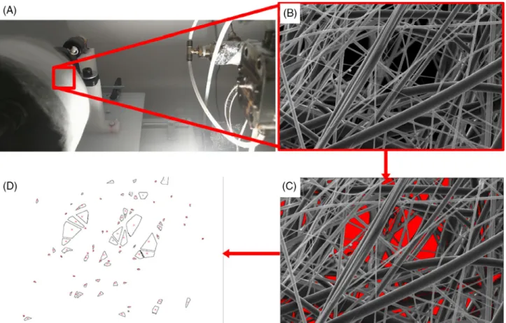
The pore size of the PP MB fiber mats was determined by using image analysis as shown in Figure 1. We tested five samples for each group. Five different images were captured for each fiber mat sample.
We counted 200 pores for each sample to analyze the MB fiber mat
average pore size distributions. A similar method has been applied by Xu44for the pore size analysis of nonwovens. The PP fiber mat samples were collected for 10 minutes for each group, and SEM tests were con- ducted for these samples. The Feret diameters were measured from the SEM images taken for each fiber mat by using ImageJ 1.51 k software.
2.7 | Tensile test
The tensile of the fiber mats was tested with a Zwick Z005 (Zwick, Ger- many) type universal tensile tester equipped with a 5 kN load cell. Rect- angular PP fiber mat samples (4 cm x 2 cm) were prepared for each test group, and the gage length was set at 2 cm and the test speed was set to 10 mm/min. The testing routine was performed five times for each sample group and the results were averaged. The tensile strength and strain at break were evaluated together with the standard deviation.
3 | R E S U L T S A N D D I S C U S S I O N 3.1 | Parameters affecting fiber morphology
Figure 2 shows the SEM images of the fibers collected at different DCDs. The figure also presents the fiber diameter distributions obtained from the image analysis.
F I G U R E 1 A step-by-step illustration of the pore size measurement by image analysis method. (A) the actual optical image of the fibers collected, (B) SEM image of the fibers, (C) automatic detection of the pores by color threshold analysis, (D) the pore map created by the software
The DCD has an effect on the fibers clearly visible. At small DCDs there is not enough time for the air to attenuate the fibers. Therefore, higher DCDs result in smaller fiber diameters in general. We found an exponential decay of the fiber diameters (Figure 3A) with a diameter of 1.48μm at infinite distance. A vast majority of fiber attenuation takes place close to the die, considering the fiber diameter is the same as fiber-forming capillary diameter (e.g., 330μm) and only a few microns or even less at the collector still it is the more important for small diameter fibers. As the attenuation stops as the crystallization completed, it is not reasonable to further increase DCD, in our case around 300–400 mm. An increase of the fiber spinline whipping amplitude with increasing DCDs and air velocity was considered as a major mechanism that took part in fiber attenuation.45,46
We investigated the influence of air temperature and air pressure on the fiber morphology. We found that lower air temperature and lower air pressure resulted in coarser fiber morphology as expected and as shown in Figure 3B,C. A temperature too high may cause stick- ing of the molten fibers (Figure 4).47
The fiber attenuation significantly depends on the air velocity (air pressure or airflow rate). Figure 3C shows the change in the average
fiber diameter and confidence interval with increasing air pressure. In theory, the fiber attenuation continues until the velocity of the air and fiber becomes equal.38 A higher air pressure attenuates the fiber more, since the air exerts a higher forwarding drag force on the fiber.48Figure 3C (Figure S2) shows that higher air pressure also leads to a narrower confidence interval.
We investigated the influence of six different collector speeds on the fiber morphology. The average fiber diameter did not change sig- nificantly by increasing collector speed, as shown in Figure 3D (Figure S3). On the other hand, high speeds resulted in fiber necking, breakage, and fuses as shown in Figure 5. The multiple necking mostly observed for the thin fibers, for example, fiber diameter less than a micron. On the other hand, fiber fuses might originate from the sepa- rate fibers stretching, which disrupt the particular fiber travel. In this phenomenon, some of the free molten polymer jets having larger diameter meet some thin fibers on the way to the collector, and they stick to each other before reaching the collector. These relatively low- velocity thick molten fibers accumulate the thin fibers around their surface. This phenomenon might occur at a very early stage of the fiber formation where fibers are close to the die and still have high F I G U R E 2 SEM images and related diameter distributions of melt blown PP fiber mats collected at different die-to-collector distances (DCD), (A)-(A') DCD = 50 mm; (B)-(B') DCD = 150 mm; DCD = (C)-(C') 400 mm
KARAANDMOLNAR 5
temperatures. What is more, higher collection speeds caused forma- tion of spherical particles which are called shot defect, as shown in Figure 5B. This defect formation mechanism sourced by the instabil- ities driven by the polymer surface tension that is resulted in fiber necking and break up.20 It is a similar imperfection seen at electrospinning due to the low solution viscosity.49Nevertheless, the fiber fuse, shot and fiber breakage might be due to the higher
collection speeds with lower collecting distance (DCD) and high air velocity and high air and melt temperatures.
We investigated the fiber orientation produced at various collec- tor speeds (Circumferential velocity) and air pressure as two factors dominating the fiber orientation. Since fibers are physically carried onto the collector surface toward the direction of collector rotation, it is intuitive to expect an orientation. In the case of high air pressure F I G U R E 3 Average fiber diameter and 95% confidence intervals versus variable (A) die-to-collector distance (DCD), (B) air temperature, (C) air pressure and (D) collector speed
F I G U R E 4 Scanning electron microscopy images of melt blown fiber imperfections, fiber fuses and fiber sticking. These imperfections formed at pressurized air temperatures of (A) 300C and (B) 125C
levels, narrower fiber flow approaching the rotating collector might provide an orientation toward the collector rotation direction. We found that only the highest collector speed (105.5 m/min) and high air pressure levels (2.25 and 2.5 bar) resulted in significant orientation (Figure S4), but at the same time it led to imperfections in the mor- phology. The results obtained are given in Table 1. The low level of orientation is considered as a result of high fiber velocity, which is believed to be faster than the collector velocity.
3.2 | Porosity and pore size
We tested density and porosity of the MB nonwoven produced at various DCD, air temperature, and air pressure. Results obtained are shown in Figure 6, while the measurement data are presented in the Supporting Information (Tables S2–S4).
We found that porosity and pore size of the PP MB nonwoven changes as a function of both the DCD, the air temperature, and the air pressure. Increasing DCD first decreases and then increases the porosity slightly. This is related to the projection of the fiber flow along with its travel from die to the collector.50,51Besides, the high air turbulence at longer DCDs causes the fibers to lay down over a wider area, decreasing fiber mat solidity (fiber packing density) and resulting
in a softer, fluffy structure.52Decreasing fiber diameter with increas- ing DCD until 200 mm resulted in a smaller pore size compared to the lowest DCD. However, fiber packing density decreased continuously with increasing DCD due to wider fiber flow projection and less fiber entanglement.
Rising the air temperature decreased the fiber diameter continu- ously, resulting in a decrease in the pore size with more fibers in- stack. However, the change in the fiber mat porosity fluctuated with increasing air temperature from 125 to 300C. Due to the fiber fuses mentioned earlies, the pores within the fiber mat became larger despite the thinner fiber diameters and the solidity decreased. The fiber mat thickness obtained at the lowest air temperature (125C) was very thin compared to those higher air temperature ones; there- fore, the resultant fiber mat exhibited higher porosity with thicker fibers and larger pore size.
On the other hand, increasing air pressure resulted in narrower fiber flow in-width. It rose the mat thickness above 2 bar. The mat thickness correlates with the fiber packing density, which is a primary factor in determining the pore size. Increasing air pressure slightly increases the fiber packing density, and this resulted in relatively smaller pores and increased mat thickness.
Results obtained from the porosity and pore size analysis were summarized in Figure 6D. In the most accepted models, the fiber mat F I G U R E 5 Scanning electron microscopy images of melt-blown fiber imperfections, -fuses, -sticking and -necking. These imperfections formed at (A) 80.4 m/min and (B) 105.5 m/min
T A B L E 1 Variation of the Herman's orientation factor for the air pressure and collector speed tests
Circumferential velocity [m/min] Herman's orientation factor [f] Air pressure [bar] Herman's orientation factor [f]
0 0.0135 1 0.0818
12.5 0.0930 1.5 0.0605
35.1 0.0597 2 0.0930
57.7 0.0774 2.25 0.1504
80.3 0.0612 2.5 0.1407
105.5 0.2343 - -
KARAANDMOLNAR 7
pore size decreases with decreasing fiber diameter.53-56The 2D col- ored contour plot illustrated in Figure 6D showed that pore size is highly dependent on the solidity which is in a good agreement with the literature.53However, processing parameters plays crucial role on the fiber mat pore size and solidity. Smaller fiber diameters are desired in order to produce a fiber mat with high packing density.57Highest air temperature and pressure applied showed relatively lower pore size with decreased fiber diameter. In the current study, the average pore size of the MB fiber mats decreased with decreasing fiber diame- ters except for the DCD test. In that case the solidity decreased that can explain the phenomenon. The widened fiber flow and increased air turbulence prior to collection resulted a larger pore size. On the other hand, the low air temperatures decreased the fiber entangle- ments and fiber to fiber contact (e.g., less fiber entanglement). This resulted in thicker fibers and large pores despite the relatively high solidity.
3.3 | Tensile properties
The experiments were conducted with the same samples once used for the porosity and density measurements, and we investigated sam- ples cut in the machine direction (Figure S5) only. The results obtained are given in Table S5 in detail. Melt-blowing typically generates self- bonding or self-penetrated fiber mats that derive their strength from fiber-to-fiber contacts besides the intrinsic material properties, for
example, crystallinity. Therefore, newly formed fibers ability to pene- trate to the fibers already on the collector affects the fiber mat's load- bearing capability upon applied stress. As a result, the tensile strength decreased continuously with increasing DCD.58Besides, higher DCDs possess less entanglements and reduces fiber packing density (Tables S2–S4); hence, the PP fiber mat tensile strength decreased, but strain at break increased with increasing DCD (Figure 7A).
Self-bonding of the fibers within the mat structure improved with increasing air temperature. In addition to this, the packing density of the PP fiber mats increased with increasing air temperature due to the higher fiber attenuation rates, which resulted in thinner fibers. The air temperature tests showed that decreasing fiber diameter and improved self-bonding enhanced the tensile strength as shown in Figure 7B.
Results showed that higher air pressure resulted in stronger PP fiber mats. This is because increasing fiber packing density and thinner fibers collected with increasing air pressure. The improved tensile strength is accompanied by a mechanically consolidated fiber mat structure. Nevertheless, slightly increased solidity with increasing air pressure resulted in more fiber entanglements and continuously lower the PP MB fiber mat strain at break. The slight decrease of the tensile strength over 2 bar air pressure is attributed due to the fast cooling of fibers with increased air velocity which resulted in frozen crystal segments.
We analyzed the influence of the average fiber diameter and the average pore size on the mechanical properties as a function of the F I G U R E 6 Variation of the porosity and pore size versus (A) die-to-collector distance, (B) air temperature, (C) air pressure. (D) 2D counter plot representing the influence of the average fiber diameter and fiber mat solidity on the average pore size
fiber mat solidity as shown in Figure 8. The results obtained showed that the fiber mat solidity and the average pore size were indicators for higher tensile strength considering the average fiber diameter. We found that larger pore sizes resulted in poor mechanical characteris- tics. The larger pores within the mat caused less fiber-to-fiber contact and deteriorated the mechanical properties as shown in Figure 8A and Figure S6. PP fiber mat collected at the lowest DCD with relatively larger fiber diameters had the highest tensile strength. This is attrib- uted to the improved crystallinity sourced by the slower cooling rate.26,59On the other hand, systematic investigations showed that
the PP fiber mat produced at optimum conditions could achieve high tensile strength (6 MPa) with an average fiber diameter of 2.5μm and 10% solidity. We found that the fiber packing density and the average fiber diameter cannot correlate to the MB fiber mat mechani- cal properties due to instabilities originating from the air drag and temperature field. But the fiber packing density and the average fiber diameter can give a raw estimation about the resultant fiber mat's mechanical properties. In addition to this, the mechanical properties depend on the crystalline structure, where the cooling rate is domi- nantly determined by the processing parameters.
F I G U R E 7 Variation of the tensile strength and strain at break for MB PP fiber mats versus various (A) die-to-collector distance (DCD), (B) air temperature and (C) air pressure
F I G U R E 8 2D counter plot representing the influence of melt-blown PP fiber mat solidity and tensile strength on the (A) average pore size and (B) the average fiber diameter
KARAANDMOLNAR 9
3.4 | Analysis of the fiber formation mechanism and the fiber structure development: DSC and WAXD tests
We investigated the influence of the parameters on the thermal prop- erties of the PP MB fibers and the sheet. DSC results showed that the crystalline melting characteristics of the fiber and the sheet exhibit different crystalline structure. The DSC results are shown in Figure 9, while the deconvoluted DSC thermograms are given in Figure 10. The DSC 1st heating cycle shows single melting peaks for the MB PP fiber samples, while the hot-pressed sheet shown a double melting peak.
On the other hand, the 2nd heating cycles (in which the fibers are tested in an already fused state) exhibited a similar, double endother- mic peak for all the samples, which confirms that the fiber structure clearly influences the crystalline phase domains.
The two peaks can be associated with different crystal forms, crystal perfections, isotropization, recrystallization, or reorganization of the crystalline domains.26,33,60The first heating gives more impor- tant information, since that corresponds to the crystalline structure gained by melt blowing at certain processing parameters. The single peak indicates a higher intrinsic orderliness (e.g., increasing orientation and alignment of the polymeric chains), which is restricted by the fiber boundary. In addition, we observed a slight increase (2C) in peak melt temperature of fiber samples compared to the sheet. In order to investigate the two melting endotherms and further analyze the influ- ence of the processing parameters, the heating curves were deconvoluted.
In addition, degree of crystallinity of the fibers varied between 43 and 52%, for which we observed the highest crystallinity at DCD of 50 mm. On the other hand, the lowest crystallinity observed for the fibers collected at DCD of 200 and 300 mm. The higher crystallin- ity for the fibers collected at DCD higher than 300 mm is related to decreasing fiber diameter (higher intrinsic orderliness) despite the increasing cooling rate and fiber velocity (Figure 11A). The air pres- sure test DSC scans (Figures S7 and S8) exhibited the same tendency seen for the DCD tests. We found that the crystallinity of the fibers
was decreased slightly with increased air pressure and air tempera- ture. It is because the higher air velocity can cool the fibers faster that hinders the crystallization (Figure 11B,C).
The DSC curves of air temperature tests, air pressure tests, and DCD tests were similar, and therefore, we present the DSC thermo- grams (Figures S9 and S10) and data in the Tables S6–S9. The degree of crystallinity of the PP MB fibers changed slightly (52–55%) at the air temperature tests. Increasing air temperature yields to the freer act of the polymeric chains. But the polymer chains did not have enough time to arrange themselves and complete full crystallization due to fast cooling, which becomes dominant with an increasing tem- perature difference between air and fibers. Therefore, PP MB fiber sample generated at higher air temperature resulted in lower crystal- linity. These results are in good agreement with the findings from DCD and air pressure tests.
We analyzed the DSC 1st and 2nd heating melting enthalpies of the fiber samples to determine the influence of air quenching as shown in Figure 12. The second heating melting enthalpies of each sample showed similar results with slight scattering. However, the cooling rate's influence resulted in a significant change between the first and second heating melting enthalpies. In the lowest DCD, the difference was small, where the fibers possess a relatively high- temperature field near the die. Increasing DCD resulted in the fast cooling of the fibers, and therefore the change in the first and second heating melting enthalpies is large. We found that the change became smaller over the DCD of 400 mm. Higher fiber crystallinity in this DCD range is attributed to the smaller fiber diameters and increased molecular orientation. On the other hand, the PP hot-pressed sheet crystallinity based on the DSC first and second heating were 49.3 and 53%, respectively, while the crystalline melting peak temperature did not change significantly. The slight change in DSC heating data of the PP hot-pressed sheet was found negligible.
The MB fiber mat porosity, fiber diameter, pore size, mechanical and thermal properties might be affected by many factors, including melt-blowing conditions and material properties. This revealed a dis- tinct relationship between process, property, and structure for
F I G U R E 9 The DSC thermograms of melt-blown PP fiber mats produced at various die-to-collector distances (DCD, data in mm) and the PP hot-pressed reference sheet at heat ramp of 10C/min; (A) first heating and (B) second heating
analyzing MB fiber mats overall. Results showed that high solidity, low porosity, and small pore size resulted in higher tensile strength, and the fiber diameter was directly related to these two properties.
Therefore, we introduced a new factor, namely, mat consolidation coefficient (MCC), to correlate the relationship between fiber mat solidity, porosity, average fiber diameter, and average pore size. The MCC is calculated by using Equation (7).
MCC =S×df,m
DPm ½ − ð7Þ
where df,mis the average fiber diameter andDPmis the average pore size. The MCC gives quantitative information on the fiber mat self- bonding quality considering fiber mat pore size, fiber diameter, and solidity. Therefore, it correlates the fiber mat tensile strength by tak- ing into account the influence of processing parameters. The MCC is a F I G U R E 1 0 Deconvoluted DSC thermograms of melt-blown PP fiber mats produced at various die-to-collector distances (DCD, data in mm) and the PP hot-pressed reference sheet at heat ramp of 10C/min; (A) first heating and (B) second heating
F I G U R E 1 1 The influence of various (A) die-to-collector distance, (B) air pressure and (C) air temperature on the fiber mat's crystal melting enthalpy and on the fiber diameter
KARAANDMOLNAR 11
dimensionless macroscopic factor that can only assume values in the range 0 < MCC < 1. Otherwise, the use of MMC to quantify mat properties has limitations. When MCC's value is 1, it means a solid
structure without any pore. Results obtained showed that MCC exhibits a linear tendency in the range of 0.07–0.27 versus the tensile strength. If the MCC is high, it describes finely self-bonding and good F I G U R E 1 2 The effects of various melt blowing parameters on the melt-blown PP fiber's crystalline melting enthalpies. Variation of the corresponding melting enthalpies obtained from the first and second heating versus various (A) die-to-collector distance (DCD), (B) air pressure and (C) air temperature
F I G U R E 1 3 The mat consolidation coefficient (MCC) analysis of the melt-blown fiber mats. (A) Relationship of MCC with the tensile strength. (B) 2D contour plot representing the correlation between MCC, tensile strength and melt-blown PP fiber crystalline melting enthalpy
mechanical properties, while low MCC defines a fiber mat with poor self-bonding and weak mechanical properties. Results showed that the measured fiber mat tensile strength data exhibit a well-fitted lin- ear function with the MCC's calculated data, as shown in Figure 13A.
In general, higher fiber crystallinity is associated with enhanced mechanical properties.61We found that the fiber-making parameters significantly influence the thermal properties of the MB fiber mats.
Besides, the processing conditions determine the fiber mat's physical properties (e.g., porosity, diameter, self-bonding quality); hence, it influences the fiber mat's mechanical properties. Therefore, we ana- lyzed the property-process-structure relationship through MCC, ten- sile strength, and crystalline melting enthalpy for MB fiber mat produced over a wide range of melt blowing conditions. The results obtained were illustrated by a 2D contour plot and shown in Figure 13B. The MB fiber mat tensile strength increased with increas- ing MCC. Besides, high MCC resulted in higher crystalline melting enthalpy. However, crystalline melting enthalpy did not exhibit any trend by either increasing or decreasing MCC. This fundamental dif- ference occurred due to the air quenching effect during the melt blowing process. The red zone, where the crystalline melting enthalpy is high, around MCC of 0.12, shows that the tensile strength is low.
This result represented the influence of processing conditions. High porosity and thick fibers resulted in a poor fiber mat consolidation despite the high fiber crystallinity due to the air annealing. On the other hand, the green zone in 2D contour at low MCC represents thin fibers, low porosity, and low fiber crystallinity caused by air
quenching. The higher MCC tended to higher fiber crystallinity and tensile strength. These results suggested that the MCC might be com- prehensively used to define the MB fiber mats' process-property- structure relationship.
The WAXD results showed that the crystalline phase transitions from theαphase (monoclinic) to the mesomorphic form took place at melt blowing. The mesomorphic mesophase can form at cooling rates high enough to prevent the crystallization of the more stable mono- clinic αform.27,35We investigated the crystal structure of the pro- duced MB fiber mats and hot-pressed sheet to analyze the influence of the processing conditions (Figure 14). The hot-pressed sheet showed Bragg reflection peaks (Figure 14A) at planes 14, 21.1, 21.7, 21.1, 27.2, and 28.5correspond to monoclinicαcrystal form on the planes of (110), (111), (041), (141,200,210), and (220), respec- tively. On the other hand, we observed X-ray diffraction peaks of the PP orthorhombicγcrystal form at 16.7, 18.4, 24.2, and 25.3corre- spond to index planes of (008), (022), (206), and (00 12), respectively.
The chain mobility is restricted by the fiber boundary. Unlike the fiber formation mechanism, the polymeric chains arranged themselves freely with high mobility during the processing of the PP hot-pressed sheet and that might in turn gives a different crystalline form. Results obtained by the WAXD analysis of the PP hot-pressed sheet suggest that lamellar branching occurred with two different crystal forms that suggestαcrystals act as a nucleus for theγcrystals. For this, we found that X-ray diffraction peaks consisted of the superposition of theαPP parent andγPP daughter crystals.43,62Besides, these results explain
F I G U R E 1 4 The wide-angle X-ray diffraction spectra of the samples tested. (A) reference PP hot-pressed sheet, melt-blown PP fiber mats produced at various melt blowing conditions; (B) die-to-collector distance (DCD; 50, 150, and 500 mm), (C) air temperature (125, 225, and 300C) and (D) air pressure (1, 2, and 2.5 bar)
KARAANDMOLNAR 13
the double melting peaks obtained by the DSC study. This phenome- non might be attributed to the low viscosity and low molecular weight of the PP fiber grade resin used.
Air drawing of the polymer jets in the melt blowing aligns PP mol- ecules; however, the subsequent air quenching could freeze crystal- line domains and render crystal phase transition. Findings showed that stress applied by high-speed hot air flow diminished theγ-phase, and transformed to theαand mesomorphic phase for the fiber sam- ples.63To have a better understanding of the crystal structure of the PP fibers, we tested higher heating and cooling rates (20C/min) in DSC for the samples obtained from the air temperature tests (Figure S11). Increasing heating and cooling rate in DSC resulted in a single melting peak for both fiber samples and the hot-pressed sheet except the PP MB fiber mat produced at the highest air temperature (300C). This sample exhibited a double melting endotherm in the sec- ond heat cycle. This change in melting characteristics is attributed to the high shearing and low viscosity when very high air temperature applied. On the other hand, higher heat ramp caused a small cold crys- tallization peak except the hot-pressed sheet at the 1st heating cycles.
The WAXD and DSC finding suggested that PP fibers cannot com- plete the crystallization during the melt blowing because of the intense air quenching. Besides, these results indicate different crystal forms in PP MB fibers compared to the hot-pressed sheet. The second heating thermograms showed that the double melting peak and there- fore,γcrystal form could be eliminated by increasing heating rates.
We found that the crystal phase transformation due to the fast cooling of the fiber resulted in decreasing mechanical properties for the higher air velocities applied. On the other hand, the mechanical characteristics of the PP MB fiber mats produced at lower air pres- sures were also influenced by phase transition and fiber packing den- sity and fiber entanglement.
Findings suggest that double meting peak sourced by theαandγ epitaxial growth was precluded in the case of the MB fiber samples due to restricted molecular motion by the fiber boundary. In addition, the smaller size of crystal with lower degree perfection for the fiber samples avoided the double melting peak formation (first heating cycle) observed in the DSC study. Upon second heating in DSC, both fiber and sheet samples exhibited the same crystal melting behavior.
The calculated crystal size and lattice spacing data through the WAXD analysis are given in Tables S10 and S11.
In the WAXD patterns, diffraction peaks slightly broaden as the crystallite size decreases by increasing air temperature and DCD.
Results showed that increasing DCD more emphasized the air quenching with larger fiber attenuation; therefore, the high-velocity fibers were cooled faster compared to the lower DCDs. This change in DCD caused a crystal phase transition from monoclinicαform to mesomorphic form as shown in Figure 14B. PP mesomorphic phase has been characterized as an ordered intermediate between the crys- talline and amorphous phases.64The PP MB fibers produced at DCD of 500 mm showed mesomorphic crystal peak diffractions around 2θ= 15 and 2θ= 22, which indicates the coupled effect of the air quenching and fiber attenuation on the fiber structure development.
Increasing air temperature significantly reduced the crystal size with
decreasing fiber diameter. We observed a slight shifting of theα(110) plane 2θBragg reflection and interplanar lattice spacing with increas- ing air temperature. This indicates a rise in the content of the meso- morphic phase in theαform. There is a definite change in PP MB fiber structure and is confirmed with WAXD analysis. The related data are given in Tables S10 and S11.
4 | C O N C L U S I O N
In this study, we explored the structure and morphology, thermal and mechanical properties and feasibility of producing self-bonded PP fiber mats by melt blowing. We found that fiber diameter decreases with increasing DCD, air pressure and air temperature while the influ- ence of the tested collector speeds on the fiber diameter was negligi- ble. Results showed that the effect of temperature difference between the forming fibers and pressurized air plays a crucial role. A large fiber attenuation occurred around 74% by increasing air temper- ature from 125 to 300C. Increasing air pressure from 1 to 2.5 bar and DCD from 50 to 500 mm reduced the average fiber diameter nearly threefold and twofold, respectively. However, changing collec- tor speed did not significantly affect the average fiber diameter, while higher collecting speeds developed fiber orientation in the collection direction. The fiber crystallinity slightly decreased (nearly 6%) with increasing air pressure and its influence became dominant when the air pressure rose over the 2 bar. On the other hand, the fiber crystal- linity decreased, associated with fast cooling of fibers, by around 16%
by increasing air temperature from 125 to 300C. On the other hand, increasing air pressure and DCD reduced fiber crystallinity by 6 and 8%, respectively. The fiber mat produced at an air pressure of 2 bar exhibited higher tensile strength around 36 and 20% compared to low and high air pressure test samples, respectively. The weakening of the mechanical properties over 2 bar air pressure is attributed due to the weak self-bonded fiber mat structure and fewer crystallinity sourced by the intense air quenching. Despite the smaller fibers obtained at higher DCDs, the fiber mat tensile behavior's weakening is attributed to the lower fiber solidity and fiber crystallinity. It is concluded that the applied low DCDs, low air velocities, and low air temperature yield a slower cooling rate and, hence, higher fiber crystallinities. However, it is revealed that the fiber mat tensile behavior primarily depends on the physical properties (e.g., pore size, solidity). Increasing air temper- ature from 125 to 300C enhanced the tensile strength around 48%
while increasing DCD from 50 to 500 mm decreased the tensile strength threefold. The tensile behavior of the PP fiber mats was transformed from ductile to brittle with increasing air temperature and air pressure, which indicates more fiber entanglements and change in the crystalline structure. On the contrary, decreasing DCD exhibited higher tensile strength and lower strain at break.
Despite slightly higher crystallinity of the fibers collected at the highest DCD, the tensile strength of the fiber mat decreased with increasing DCD due toα!mesomorphic phase transition. Increasing air pressure and DCD caused faster cooling; therefore, the resultant MB fibers exhibited less crystallinity due to frozen crystallite domains.
The WAXD analysis revealed that crystalline, amorphous, and meso- morphic phases were formed in the MB PP fiber's structure. The con- tent of those phases changed over a wide range depending on the processing conditions, the temperature field between the collector and die. The hot-pressed reference PP sheet showed the existence of theα–γepitaxial relationships, which is attributed to formation ofα PP lamellae (called parent) growing normal to the PP hot-pressed sheet surface, andγPP branches (called daughter) nucleated by these parents. The WAXD profile analysis showed that increasing air pres- sure and air temperature showed a slight increment in the fraction of the mesomorphic phase. Generating perfectly crystalline, hence high strength MB fibers require mainly minimizing the temperature gradi- ent between fiber and ambient. Besides, applying high air stretching necessary to enhance molecular orientation and form smaller crystal- lite sizes. Producing thinner fibers at the expense of the MB fiber mat's mechanical characteristics can down the pore size and higher solidities. However, applied high air pressure (2.5 bar) resulted in moderate tensile strength (5 MPa) and low pore size (1.4μm) while the fiber crystallinity was reduced due to the fast cooling of fibers.
These findings suggest that PP MB fiber structure development from micro to macroscale is significantly affected by melt blowing condi- tions. Results showed that the melt-blowing parameters do not go hand in hand producing thinner, high strength and porous fine MB fiber mat. We observed a close relation with fiber diameter, pore size, solidity and tensile strength, for which we introduced a factor of MCC. Findings proved that MCC can be used comprehensively to analyze fiber mat properties considering influence of processing parameters. The MB fiber mats used in various applications, such as masks, respirators and filtration, protective clothing, super- hydrophobic membrane, agriculture, composite structures, super- absorbent, etc., possess differing requirements. In this aspect, the results presented in this study provided a systematic and more-in- depth process-structure-property relationship on understanding the MB fiber formation and resultant fiber mat characteristics.
A C K N O W L E D G E M E N T S
The authors thank to Borealis Polymers N.V. and Henk van Paridon for supplying the raw material used in this work. Authors also thank Tamás Kolonits from the Eötvös Loránd University (ELTE), Depart- ment of Materials Physics for XRD measurements. This paper created at the Budapest University of Technology and Economics was supported by the“TKP2020, Institutional Excellence Program”of the National Research Development and Innovation Office in the field of Nanotechnology and Materials Science (BME IE-NAT TKP2020). This paper was also supported by the János Bolyai Research Scholarship of the Hungarian Academy of Sciences (MTA), the by the ÚNKP-20-5 New National Excellence Program of the Ministry for Innovation and Technology and the Stipendium Hungaricum Scholarship of Tempus Közalapítvány.
C O N F L I C T O F I N T E R E S T
The authors declare there is no conflict of interest.
D A T A A V A I L A B I L I T Y S T A T E M E N T
The data that support the findings of this study are available on request from the corresponding author. The data are not publicly available due to privacy or ethical restrictions.
O R C I D
Yahya Kara https://orcid.org/0000-0001-6939-4114 Kolos Molnár https://orcid.org/0000-0002-9331-4652
R E F E R E N C E S
1. Zuo F, Tan DH, Wang Z, Jeung S, Macosko CW, Bates FS. Nanofibers from melt blown fiber-in-fiber polymer blends.ACS Macro Lett. 2013;
2(4):301-305. https://doi.org/10.1021/mz400053n.
2. Hirsch E, Vass P, Démuth B, et al. Electrospinning scale-up and formu- lation development of PVA nanofibers aiming oral delivery of bio- pharmaceuticals.Express Polym Lett. 2019;13(7):590-603. http://doi.
org/10.3144/expresspolymlett.2019.50.
3. Shirwaiker RA, Fisher MB, Anderson B, et al. High-throughput manu- facture of 3D fiber scaffolds for regenerative medicine.Tissue Eng Part C Methods. 2020;26(7):364-374. https://doi.org/10.1089/ten.
tec.2020.0098.
4. Salehi MM, Hakkak F, Sadati Tilebon SM, Ataeefard M, Rafizadeh M.
Intelligently optimized electrospun polyacrylonitrile/poly(vinylidene fluo- ride) nanofiber: using artificial neural networks.Express Polym Lett. 2020;
14:1003-1017. https://doi.org/10.3144/expresspolymlett.2020.82.
5. Luiso S, Henry JJ, Pourdeyhimi B, Fedkiw PS. Fabrication and charac- terization of Meltblown poly (vinylidene difluoride) membranes.ACS Appl Polym Mater. 2020;2(7):2849-2857. https://doi.org/10.1021/
acsapm.0c00395.
6. Wente VA. Superfine thermoplastic fibers.Ind Eng Chem. 1956;48(8):
1342-1346. https://doi.org/10.1021/ie50560a034.
7. Xiao H, Gui J, Chen G, Xiao C. Study on correlation of filtration per- formance and charge behavior and crystalline structure for melt- blown polypropylene electret fabrics.J Appl Polym Sci. 2015;132(47):
1-6. https://doi.org/10.1002/app.42807.
8. Roh S, Park K, Kim J. Design of web-to-web Spacing for the reduced pressure drop and effective depth filtration.Polymer. 2020;11:1882.
https://doi.org/10.3390/polym11111822.
9. Li H, Huang H, Meng X, Zeng Y. Fabrication of helical microfibers from melt blown polymer blends.J Polym Sci B. 2018;56(13):970-977.
https://doi.org/10.1002/polb.24618.
10. Jenkins T, Meehan S, Pourdeyhimi B, Little D. Meltblown polymer fabrics as candidate scaffolds for rotator cuff tendon tissue engineer- ing.Tissue Eng Part A. 2017;23(17–18):958-967. https://doi.org/10.
1089/ten.tea.2016.0470.
11. Balogh A, Farkas B, Farago K, et al. Melt-blown and electrospun drug- loaded polymer fiber mats for dissolution enhancement: a compara- tive study.J Pharm Sci. 2015;104(5):1767-1776. https://doi.org/10.
1002/jps.24399.
12. Wang Z, Macosko CW, Bates FS. Fluorine-enriched melt-blown fibers from polymer blends of poly(butylene terephthalate) and a fluorinated multiblock Copolyester.ACS Appl Mater Interfaces. 2016;8(1):754- 761. https://doi.org/10.1021/acsami.5b09976.
13. Walczak J, Sobota M, Chrzanowski M, Krucinska I. Application of the melt-blown technique in the production of shape-memory nonwoven fabrics from a blend of poly(L-lactide) and atactic poly[(R,S)-3-hydroxy butyrate]. Text Res J. 2018;88(18):2141-2152. https://doi.org/10.
1177/0040517517716906.
14. Zhang C, Tian W, Li D, Quan L, Zhu C. The high performances of SiO2-coated melt-blown non-woven fabric for lithium-ion battery separator.J Textile Inst. 2018;109(9):1254-1261. https://doi.org/10.
1080/00405000.2017.1423004.
KARAANDMOLNAR 15
15. Vadas D, Kmetykó D, Marosi G, Bocz K. Application of melt-blown poly (lactic acid) fibres in self-reinforced composites.Polymer. 2018;
10(7):766. https://doi.org/10.3390/polym10070766.
16. Mijares JL, Agaliotis E, Bernal CR, Mollo M. Self-reinforced polypro- pylene composites based on low-cost commercial woven and non- woven fabrics.Polym Adv Technol. 2018;29(1):111-120. https://doi.
org/10.1002/pat.4093.
17. Lee Y, Wadsworth LC. Effects of melt-blowing process conditions on morphological and mechanical properties of polypropylene webs.
Polymer. 1992;33(6):1200-1209. https://doi.org/10.1016/0032-3861 (92)90764-N.
18. Xie S, Han W, Jiang G, Chen C. Turbulent air flow field in slot-die melt blowing for manufacturing microfibrous nonwoven materials.J Mater Sci. 2018;53(9):6991-7003. https://doi.org/10.1007/s10853-018- 2008-y.
19. Choi KJ, Spruiell JE, Fellers JF, Wadsworth LC. Strength properties of melt blown nonwoven webs. Polym Eng Sci. 1988;28(2):81-89.
https://doi.org/10.1002/pen.760280204.
20. Ellison CJ, Phatak A, Giles DW, Macosko CW, Bates FS. Melt blown nanofibers: fiber diameter distributions and onset of fiber breakup.
Polymer. 2007;48(11):3306-3316. https://doi.org/10.1016/j.polymer.
2007.04.005.
21. Yin H, Yan Z, Ko W-C, Bresee RR. Fundamental description of the melt blowing process. Int Nonwovens J Int Nonwovens J. 2000;
9(4):1558925000OS-90. https://doi.org/10.1177/1558925000OS- 900408.
22. Xu QY, Wang YM. The effects of processing parameter on melt- blown filtration materials.Adv Mater Res. 2013;650:78-84. https://
doi.org/10.4028/www.scientific.net/AMR.650.78.
23. Guo M, Liang H, Luo Z, Chen Q, Wei W. Study on melt-blown processing, web structure of polypropylene nonwovens and its BTX adsorption. Fibers Polym. 2016;17(2):257-265. https://doi.org/10.
1007/s12221-016-5592-y.
24. Feng J. Preparation and properties of poly (lactic acid) fiber melt blown non-woven disordered mats. Mater Lett. 2017;189:180-183.
https://doi.org/10.1016/j.matlet.2016.12.013.
25. Peng M, Jia H, Jiang L, Zhou Y, Ma J. Study on structure and property of PP/TPU melt-blown nonwovens. J Textile Inst. 2018;110(3):468- 475. https://doi.org/10.1080/00405000.2018.1485461.
26. Gradys A, Sajkiewicz P, Minakov A, et al. Crystallization of polypro- pylene at various cooling rates.Mater Sci Eng A. 2005;413:442-446.
https://doi.org/10.1016/j.msea.2005.08.167.
27. Pawlak A, Galeski A. Crystallization of polypropylene. In: Karger- Kocsis J, Bárány T, eds.Polypropylene Handbook: Morphology, Blends and Composites. Cham, Switzerland: Springer International Publishing;
2019:185-242. https://doi.org/10.1007/978-3-030-12903-3_4.
28. Wang J, Gahleitner M, Gloger D, Bernreitner K.β-Nucleation of iso- tactic polypropylene: chain structure effects on the effectiveness of two different nucleating agents. Express Polym Lett. 2020;14(5):
491-502. http://doi.org/10.3144/expresspolymlett.2020.39.
29. Nayak R, Kyratzis IL, Truong YB, et al. Fabrication and characterisa- tion of polypropylene nanofibres by meltblowing process using differ- ent fluids.J Mater Sci. 2012;48(1):273-281. https://doi.org/10.1007/
s10853-012-6742-2.
30. Passingham C, Hendra P, Cudby M, Zichy V, Weller M. The re- evaluation of multiple peaks in the DSC melting endotherm of isotac- tic polypropylene.Eur Polym J. 1990;26(6):631-638. https://doi.org/
10.1016/0014-3057(90)90219-T.
31. Corradini P, Napolitano R, Oliva L, Petraccone V, Pirozzi B, Guerra G. A possible structural interpretation of the two DSC melt- ing peaks of isotactic polypropylene in theα-modification.Makromol Chem Rapid. 1982;3(10):753-756. https://doi.org/10.1002/marc.
1982.030031018.
32. Nayak R, Kyratzis IL, Truong YB, et al. Fabrication and characterisa- tion of Nanofibres by Meltblowing and melt electrospinning. Adv
Mater Res. 2012;472–475:1294-1299. https://doi.org/10.4028/
www.scientific.net/AMR.472-475.1294.
33. Paukkeri R, Lehtinen A. Thermal behaviour of polypropylene frac- tions: 2. The multiple melting peaks. Polymer. 1993;34(19):4083- 4088. https://doi.org/10.1016/0032-3861(93)90670-6.
34. Auriemma F, de Ballesteros OR, De Rosa C, Corradini P. Structural disorder in the α form of isotactic polypropylene. Macromolecules.
2000;33(23):8764-8774. https://doi.org/10.1021/ma0002895.
35. Auriemma F, De Rosa C, Malafronte A, Scoti M, Di Girolamo R. Solid state polymorphism of isotactic and Syndiotactic polypropylene. In:
Karger-Kocsis J, Bárány T, eds. Polypropylene Handbook: Morphology, Blends and Composites. Cham, Switzerland: Springer International Pub- lishing; 2019:37-119. https://doi.org/10.1007/978-3-030-12903-3_2.
36. Martuscelli E, Pracella M, Crispino L. Crystallization behaviour of frac- tions of isotactic polypropylene with different degrees of stereoregu- larity. Polymer. 1983;24(6):693-699. https://doi.org/10.1016/0032- 3861(83)90005-8.
37. Uyttendaele MAJ, Shambaugh RL. Melt blowing: general equation development and experimental verification.AIChE J. 1990;36(2):175- 186. https://doi.org/10.1002/aic.690360203.
38. Shambaugh BR, Papavassiliou DV, Shambaugh RL. Next-generation modeling of melt blowing. Ind Eng Chem Res. 2011;50(21):12233- 12245. https://doi.org/10.1021/ie200836a.
39. Daenicke J, Lämmlein M, Steinhübl F, Schubert DW. Revealing key parameters to minimize the diameter of polypropylene fibers pro- duced in the melt electrospinning process. E-Polymers. 2019;19(1):
330-340. https://doi.org/10.1515/epoly-2019-0034.
40. He H, Wang Y, Farkas B, Nagy ZK, Molnar K. Analysis and prediction of the diameter and orientation of AC electrospun nanofibers by response surface methodology. Mater Des. 2020;108902:1-11.
https://doi.org/10.1016/j.matdes.2020.108902.
41. Warrier JKS, Munshi VG, Chidambareswaran PK. Calculating Herman's orientation factor.Text Res J. 1987;57(9):554-555. https://
doi.org/10.1177/004051758705700912.
42. Ehrenstein GW, Riedel G, Trawiel P.Thermal Analysis of Plastics: The- ory and Practice. München, Germany: Carl Hanser Verlag GmbH Co KG; 2012. https://doi.org/10.3139/9783446434141.fm.
43. Meille SV, Brückner S. X-ray scattering. In: Karger-Kocsis J, ed.Polypropylene: An A-Z reference. Netherlands: Springer; 1999:890- 895. https://doi.org/10.1007/978-94-011-4421-6.
44. Xu B. Measurement of pore characteristics in nonwoven fabrics using image analysis.Cloth Text Res J. 1996;14(1):81-88. https://doi.org/
10.1177/0887302X9601400110.
45. Chung C, Kumar S. Onset of whipping in the melt blowing process.
J Non-Newtonian Fluid Mech. 2013;192:37-47. https://doi.org/10.
1016/j.jnnfm.2012.10.005.
46. Xie S, Zeng Y. Online measurement of fiber whipping in the melt- blowing process.Ind Eng Chem Res. 2013;52(5):2116-2122. https://
doi.org/10.1021/ie3024615.
47. Xie S, Zheng Y, Zeng Y. Influence of die geometry on fiber motion and fiber attenuation in the melt-blowing process.Ind Eng Chem Res.
2014;53(32):12866-12871. https://doi.org/10.1021/ie5025529.
48. Chen T, Huang X. Air drawing of polymers in the melt blowing non- woven process: mathematical modelling. Model Simul Mater Sci Eng. 2004;12(3):381-388. https://doi.org/10.1088/0965-0393/12/
3/002.
49. Kara Y, He H, Molnár K. Shear-aided high-throughput electrospinning: a needleless method with enhanced jet formation.
J Appl Polym Sci. 2020;137(37):49104. https://doi.org/10.1002/app.
49104.
50. Hammonds RL, Gazzola WH, Benson RS. Physical and thermal char- acterization of polylactic acid meltblown nonwovens. J Appl Polym Sci. 2014;131(15):1-7. https://doi.org/10.1002/app.40593.
51. Hassan MA, Yeom BY, Wilkie A, Pourdeyhimi B, Khan SA. Fabrication of nanofiber meltblown membranes and their filtration properties.
J Membr Sci. 2013;427:336-344. https://doi.org/10.1016/j.memsci.
2012.09.050.
52. Bresee RR. Fiber motion near the collector during melt blowing part 1:
general considerations.Int Nonwovens J. 2002;11(2):1558925002OS- 01100207. https://doi.org/10.1177/1558925002OS-01100207.
53. Tsai P, Yan Y. The influence of fiber and fabric properties on nonwo- ven performance. In: Chapman RA, ed.Applications of Nonwovens in Technical Textiles. Cambridge, UK: Woodhead Publishing; 2010;18- 45. https://doi.org/10.1533/9781845699741.1.18.
54. PPY T. Theoretical and experimental investigation on the relationship between the nonwoven structure and the web properties.Int Nonwo- vens J. 2002;11(4):1558925002OS-01100408. https://doi.org/10.
1177/1558925002OS-01100408.
55. Simmonds GE, Bomberger JD, Bryner MA. Designing nonwovens to meet pore size specifications. J Eng Fibers Fabrics. 2007;2(1):155892 500700200101. https://doi.org/10.1177/155892500700200101.
56. Papkov D, Zou Y, Andalib MN, Goponenko A, Cheng SZ, Dzenis YA.
Simultaneously strong and tough ultrafine continuous nanofibers.ACS Nano. 2013;7(4):3324-3331. https://doi.org/10.1021/nn400028p.
57. Mao N, Russell SJ, Pourdeyhimi B. Characterisation, testing and modelling of nonwoven fabrics. In: Russell SJ, ed.Handbook of Non- wovens. Sawston, Cambridge: Woodhead Publishing; 2007:401-514.
https://doi.org/10.1533/9781845691998.401.
58. Begenir A, Michielsen S, Pourdeyhimi B. Melt-blowing thermoplastic polyurethane and polyether-block-amide elastomers: effect of processing conditions and crystallization on web properties. Polym Eng Sci. 2009;49(7):1340-1349. https://doi.org/10.1002/pen.21244.
59. Li J, Zhou C, Gang W. Study on nonisothermal crystallization of mal- eic anhydride grafted polypropylene/montmorillonite nanocomposite.
Polym Test. 2003;22(2):217-223. https://doi.org/10.1016/S0142- 9418(02)00085-5.
60. Mileva D, Androsch R, Zhuravlev E, Schick C, Wunderlich B.
Isotropization, perfection and reorganization of the mesophase of iso- tactic polypropylene. Thermochim Acta. 2011;522(1–2):100-109.
https://doi.org/10.1016/j.tca.2011.01.005.
61. Yao J, Bastiaansen CW, Peijs T. High strength and high modulus electrospun nanofibers. Fibers. 2014;2(2):158-186. https://doi.org/
10.3390/fib2020158.
62. Dean DM, Register RA. Orientedγ-isotactic polypropylene crystal- lized at atmospheric pressure.J Polym Sci B. 1998;36(15):2821-2827.
https://doi.org/10.1002/(SICI)1099-0488(19981115)36:15<2821::
AID-POLB16>3.0.CO;2-P.
63. Jones AT, Aizlewood JM, Beckett D. Crystalline forms of isotactic polypropylene. Die Makromolekulare Chem. 1964;75(1):134-158.
https://doi.org/10.1002/macp.1964.020750113.
64. Brückner S, Meille SV. Polymorphism in crystalline polypropylene. In:
Karger-Kocsis J, ed.Polypropylene: An A-Z reference. Netherlands: Springer;
1999:606-614. https://doi.org/10.1007/978-94-011-4421-6_82.
S U P P O R T I N G I N F O R M A T I O N
Additional supporting information may be found online in the Supporting Information section at the end of this article.
How to cite this article:Kara Y, Molnár K. Revealing of process–structure–property relationships of fine
polypropylene fiber mats generated via melt blowing.Polym Adv Technol. 2021;1–17.https://doi.org/10.1002/pat.5270
KARAANDMOLNAR 17