A review of processing strategies to generate melt-blown nano/microfiber mats for high-efficiency filtration applications
Kara Y., Molnár K.
Accepted for publication in Journal of Industrial Textiles Published in 2021
DOI: https://doi.org/10.1177/15280837211019488
Powered by TCPDF (www.tcpdf.org)
1
A review of processing strategies to generate melt-blown nano/microfiber mats for high-efficiency filtration applications
Yahya Kara
1and Kolos Molnár*
1,21. Budapest University of Technology and Economics, Faculty of Mechanical Engineering, Department of Polymer Engineering, Műegyetem rkp. 3., H-1111 Budapest, Hungary
2. MTA–BME Research Group for Composite Science and Technology, Műegyetem rkp. 3., H- 1111 Budapest, Hungary
Corresponding author: Kolos Molnár (molnar@pt.bme.hu)
Abstract
Protective masks – worn properly - have become the key to wither away the COVID-19 pandemic. Nowadays, the vast majority of these masks are made of nonwoven fabrics. High- quality products have mainly melt-blown filtering layers of nano/microfiber. Melt blowing produces very fine synthetic nonwovens from a wide range of polymers and allows a fair control of the fiber structure and morphology that makes it ideal for filtration purposes. Melt blowing has a high throughput, and the low price of the filter makes these products widely available for civil use. Although melt-blown fiber applications were rapidly growing in the last three decades, we still have limited knowledge on the processing parameters. In this regard, we detailed the melt blowing parameters to obtain a filter media with high particle capturing efficiency and a low- pressure drop. We summarized the melt-blown fiber mat characteristics with specific attention to the pore size, the porosity, the fiber diameter, the fiber packing density and the air permeability desired for highly efficient filtration. Even though we cannot estimate the future social effects and the trauma caused by the current pandemic, and protective masks might remain a part of everyday life for a long while. That also implies that near-future investments in wider manufacturing
2
capacities seem inevitable. This paper also aims to facilitate masks' production with improved filtration efficiency by reviewing the recent developments in melt blowing, the related applications, the effects of processing parameters on the structure and performance of the nonwoven products focusing on the filtration efficiency via knowledge.
Keywords: melt blowing, nonwoven, filter media, fiber structure, respiratory systems, COVID-19
Nomenclature
Notation Definition Notation Definition
MB melt-blown PLA Poly (lactic acid)
ES electrospun TPE Thermoplastic
elastomers
NPL needle-punched layer PVDF Polyvinylidene
fluoride
MBL melt-blown layer PTT Polytetramethylene
terephthalate
SMS spunbond/melt-blown/spunbond PMMA Poly(methyl
methacrylate) NIOSH the U.S. National Institute for
Occupational Safety and Health PVA Polyvinyl alcohol
ECS European Committee for
Standardization PAN Polyacrylonitrile
COVID-19, SARS-CoV-2
Severe acute respiratory syndrome
coronavirus 2 PCL Polycaprolactone
MFI melt flow index PPS Polyphenylene
sulfide
DCD die-to-collector distance PDI polydispersity index
FFP filtering facepiece NaCI sodium chloride
PET Polyethylene terephthalate MgSt Magnesium stearate
PS Polystyrene TiO2 Titanium dioxide
PA Polyamide BaTiO3 Barium titanate
PE Polyethylene Zeolite
imidazole ZIF
PBT Poly (butylene terephthalate) SAP superabsorbent
polymer
PC Polycarbonate WAXD wide-angle X-ray
diffraction
3
PU Polyurethane DOP dioctyl phthalate
PCTFE Polytrifluorochloroethene TBC tributyl citrate
PMP Polymethylpentene UV Ultraviolet
PP Polypropylene CV coefficient of
variation 1. Introduction
Melt blowing is a simple, versatile and cost-effective extrusion-based technology that generates continuous nano/microfibers, forming in most cases a randomly oriented web. The fiber mat is formed continuously, the polymer melt is drawn by pressurized hot air. No special additives or binders are required, and there is no need for secondary processes like thermal bonding of the fibers. A variety of additives can be admixed to the base polymer to enhance end properties, similar to any other extrusion-based polymer processing techniques. Melt-blown (MB) fiber mats have high surface area per unit weight, and moderate stiffness and tunable permeability. These properties make them excellent candidates for making high quality filters, surgical drapes and gowns, protective apparel 1-9. In addition to these, MB nonwovens can also be utilized in a wide range of applications including drug delivery, membrane separation, battery separators, skin and wound dressing and reinforced composite materials 10-16 and they play a crucial role in the fight against the COVID-19 pandemic 17, 18 as the most common filtering media in face masks.
MB fiber mats are formed directly from a molten polymer without controlled stretching. This renders a distinct cost advantage and high production rate in comparison with other micro- and nanofiber generating techniques (e.g. electrospinning) 19-23. Besides, melt blowing is a solvent-free process that makes it economically and environmentally friendly. Moreover, melt blowing is compatible with a broad type of polymers 4. The properties of the polymer materials have to be optimized to meet the requirements of certain applications. These features may include but not limited to: hydrophobicity/hydrophilicity, piezoelectric or antistatic properties, biocompatibility
4
or biodegradability, high filtration efficiency or absorbency of liquid matters, possess a high modulus and strength, etc. Often a combination of multiple properties is desired, and that can be achieved with precisely engineered equipment operated within a rather narrow processing window, accurately designed processing parameters, or combination of two or more synthetic materials 24,
25.
The COVID-19 pandemic raised a discussion in both scientific and industrial environments on the high-throughput fine fiber making methods for producing high-efficiency filtering facepiece (FFP) protection and related respiratory systems. Notably, the respiratory devices and related applications of the MB fiber mats are the great interest of both industry and research environments.
Melt blowing is often employed in mass production to create such respiratory systems with high quality and high filtration efficiency 26. Filters made of MB fibers are widely used to capture and filter solid and liquid aerosols27 and therefore became one of the most essential protective equipment in fighting COVID-19. Respirators made of fiber mats are standardized with different codes (grades) in different countries according to their filtration efficiency. For example, they are represented as N95, N99 and N100 in the USA and KN90, KN95 and KN100 in China 28, 29. The numbers refer to the minimum filtration efficiency in percent’s (90%, 95%, 99% and 99.97%) for a standard aerosol particle size of 0.3 μm (300 nm) 30-32. In Europe, respirators are coded as FFP1, FFP2 and FFP3 having filtration efficiency of at least 80%, 94% and 99.95%, respectively 33. Respirators are also designated with N, R, P codes, which stand for not oil resistant, moderately oil resistant, and highly resistant to oil (oil proof), respectively 29. There are regulations and standards for respirators designation respectively prepared by the U.S. National Institute for Occupational Safety and Health (NIOSH) and by the European Committee for Standardization (ECS) for approval label and related requirements 29, 30, 33, 34. Approval labels provide essential
5
information to determine whether a respirator is configured in a manner consistent with conditions determined by the NIOSH and EN 149:2001+A1:2009 and EN 13274-7:2008 and GB 2626-2019 standards. The filtration efficiency ratings of the particulate respirators according to these standards are summarized in Table 1. The allowable breathing resistance (e.g., inhalation and exhalation resistance) is another key feature since it is closely related to the respiratory device's performance and comfort. Therefore, the filter media breathing resistance is standardized according to the graded filtration efficiency. For example, the EN 149:2001 breathing resistance with the inhalation flow of 95 l/min designated 210 Pa, 240 Pa, and 300 Pa for FFP1, FFP2 and FFP3, respectively, while exhalation resistance for all grades limited to 300 Pa with the flow rate of 160 l/min. On the other hand, the GB 2626-2019 standard for disposable facemask (without valve) under the same inhalation and exhalation flow rate of 85 l/min specified the breathing resistance (both inhalation and exhalation) of 170 Pa, 210 Pa and 240 Pa for KN90, KN95 and KN100, respectively. The ECS recently released a guide for face coverings. It is indicated that air permeability must be greater than or equal to 96 l/s/m2 for a vacuum pressure of 100 Pa 35. An airborne virus mostly consists of a lipid (fats and oils) sheath; however, the amount of lipid in the virion (floating virus particle) is low; therefore, it does not significantly affect the filtration performance of N series respirators. The actual size of the COVID-19 (SARS-CoV-2) virus is reported around 150 nm, and the 𝜂 ≥ 95% respirators are able to protect against particles in that range36. Thus, at least N95, KN95, FFP2 or equivalent respirators are recommended for the protection against the airborne viruses such as the SARS-CoV-2 new coronavirus for those in high risk environments 30, 37.
Table 1. Summary of the particulate respirator efficiency ratings and corresponding standards Standard
6 Particulate respirator
efficiency ratings Description NIOSH- 42CFR84
GB 2626-
2019
EN
149:2001+A1:2009 100 captures 99.97 particles
out of every 100 N100 KN100 FFP3
99 captures 99 particles out
of every 100 N99 KN99 N/A
95 captures 95 particles out
of every 100 N95 KN95 FFP2
90 captures 90 particles out
of every 100 N90 KN90 FFP1
The high barrier properties against fluids, breathability and efficient particulate and droplet filtration are essential features for the respirators made of nonwovens 38, 39. The fundamental problem in respiratory filtration systems is ensuring and selecting an appropriate structure of the fiber mats. The filter media is expected to provide high efficiency for various types of conditions
40. Choosing appropriate processing parameters in generating fiber mats could significantly enhance the end properties of MB fiber mats, hence the filtering properties. Filtration is a complex process that consists of transportation mechanisms and the deposition of particles on the fiber media. In practice, nonwoven filters are expected to have features like low energy consumption of manufacturing, longer service time, mechanical durability, high filtration capacity, easy cleanability and easier maintenance. The filtration efficiency of the MB fiber mats depends on the geometric dimensions of the fibers, thickness, porosity (or packing density) and besides, the nature of the aerosol, the particle size, and environmental conditions such as temperature, relative humidity and air velocity also influence the filtration efficiency 1, 8, 41-43.
Pore size or pore diameter is very important in determining the filtration efficiency of a nonwoven filter. Pore size is directly related to the fiber diameter, the solidity (fiber packing density) and the thickness of the mat. Solidity is the volume of fibers per unit volume of fiber mat,
7
and it depends on the fiber diameter and geometry within the fibrous structure (i.e., fiber mat). The relationship between pore size, solidity and fiber diameter is given by Eqs 1 and 2 38, 44.
𝜒 =𝑉𝑉𝑓
𝑓𝑚 = (
𝜌𝑏𝑢𝑙𝑘𝑚𝑓𝑚
𝑡𝑓𝑚𝐴𝑓𝑚) = 1 − ε (1)
D̅ =g(𝜒)𝑑𝑓 g(𝜒) = 1
[2(1−𝜒)2𝜒1.5(1+56𝜒3)1 ]0.5
(2)
where, 𝜒 is the solidity, 𝑉𝑓𝑚is the volume of the fiber mat (or medium), 𝑉𝑓is the volume of the fibers, 𝑡𝑓𝑚 is the thickness of the fiber mat, 𝑑𝑓 is the fiber diameter, 𝜌𝑏𝑢𝑙𝑘 is the bulk density of the polymer, 𝑚𝑓𝑚 is the mass of the fiber mat (or medium), 𝐴𝑓𝑚is the area of the fiber mat, ε is porosity and D̅ is the average circular capillary-equivalent pore size (derived from the modified Hagen–Poiseuille law).
The fiber mat thickness (e.g., filter depth) and areal density (i.e., surface area per unit mass) are directly related to the filtration performance. Increasing fiber mat thickness and areal density may increase the filtration efficiency. However, this often worsens the filter media properties, such as pressure drop, air permeability, inhalation/exhalation comfort, etc. 38, 45, 46. Therefore, reducing the fiber diameter and pore size might be a good strategy to adjust the fiber mat thickness and areal density, and so filtration efficiency. Finer the fiber diameter increases the specific surface area, and that in turn gives decreasing pore size 46. Besides, finer fibers resulted in thinner fiber mat thickness and increases fiber-specific surface area 19. Decreasing fiber diameter increases fiber- specific surface area, decreases the filter media pressure drop in parallel 47.The pore size also decreases due to the fiber entanglements. With larger diameter fibers, due to their higher bending
8
stiffness, entanglements will be relatively less. Therefore, generally, nonwovens have no structural barriers restricting their use as filters. The filter pressure drop characteristic is related to the filter thickness, fiber diameter, fiber packing density and filter media’s rigidity. However, decreasing fiber diameter results in thinner filter thickness, which might weaken the filter media’s mechanical properties 27, 48. Filter media strength to maintain its structural integrity against the pressure of the fluid flowing through it which is crucial for its operational use.
Although MB fiber mats exhibit high filtration performance, they suffer from weak mechanical properties and poor abrasion resistance. A filter media made of fine fiber (e.g., electrospun or MB) mats are reinforced with external layers to provide structural integrity in facemask applications49. These layered structures (i.e., composite) provide density and porosity gradient filtration. Each successive layer provides a high efficiency for capturing smaller particles when the liquid and particle flow through the filter50. The SMS (spunbond/melt-blown/spunbond) process and variations are commonly implemented in producing filters due to their good mechanical properties and feasible production on a large-scale51, 52. Air permeability is another property which determines the filtration efficiency and quality of the nonwovens. It is defined as the rate of airflow passing perpendicularly through a known area of the filter under a certain pressure difference between the two sides of the filter 53. It provides a measure of nonwoven porosity and relates directly to its thickness and density. Low air permeability filter media are desired for efficient filtration considering particle capturing in the air more effectively. However, too low air permeability is not favorable for air filter media, because it reduces the inhalation and exhalation quality and people wear the mask less-likely. On the other hand, higher air permeability gives, in turn, better breathability. When the air permeability is high, the exhaled air might go through filter media smoothly, and the user comfort will be better in terms of inhalation and exhalation. The
9
COVID-19 outbreak revealed that the user’s comfort related to air permeability is one of the biggest challenges in making face masks (e.g. N95, KN95, FFP3) made of MB fiber mats.
Therefore, air permeability in terms of filtration application needs a systematic optimization for high-quality filter media. Despite the higher air permeability render a good barrier property of fiber mats, it is not favorable for applications such as respiratory devices since it reduces filtration efficiency.
There is a close relationship between the pore diameter, the fiber diameter and the air permeability, which are crucial for filtration efficiency 54, 55. However, these properties do not go hand in hand, one has to compromise to get the parameters close to the desired. However, high bulk density and air high permeability with the smallest pore sizes are expected for highly efficient nonwoven filters. Smaller fibers yield small pore size and high filtration efficiency. On the other hand, larger fibers might provide bulky media and improved permeability, but that could, in turn, give a significant loss in filtration efficiency 3.
Up to date, a massive effort has been dedicated to fundamentally understand and to improve the filtration efficiency of MB fiber mats and the fiber formation process itself. In the present study, we aim to detail the current scientific and technological advances in melt blowing, and MB fibers used in filtration applications. Our other goal is to develop an overall and more in-depth understanding of the relationships of the melt blowing process, the structure and the filtration performance.
2. Melt Blowing Process and Related Polymeric Materials
In melt blowing, the polymer melt is extruded through a die containing numerous small capillaries then stretched via a jet of hot air. The ratio of high velocity air versus the lower velocity polymer provides a drag force that rapidly attenuates the forming fibers. Then, the fibers are
10
collected on the surface of a collector in the form of a random web. The method was first developed in the 1950s at the U.S. Naval Research Laboratory by Wente with the goal of making sub-micron fibers to trap radioactive particles in the upper atmosphere 56. Wente was able to generate polyamide and polyester fibers with a diameter of less than 1 micron and as thin as 100 nanometers by hot air steam. The concept of Wente is consisted of a ram extruder that forced a molten polymer through a row of capillary holes directly into high velocity heated air. The fibers formed through the gas steam when cooler ambient air solidified the molten polymer towards the collector. This concept was quite similar to the manufacturing of mineral wool patented by John Player 57 in 1870.
The patented process involved blowing a strong stream of air across a falling flow of liquid iron slag. When a powerful blast of steam met the liquid slag, that separated the melt into long filaments. The industrialization of a similar method was carried out by another patent by Charles Corydon Hall 58 in 1902 to produce a highly porous mineral-wool felt. The idea of applying hot air steam for fiber generation had been followed by another patent authored by John H. Thomas of the Owens-Corning Fiberglass Corporation 59 in 1940 to manufacture glass wools. After the first steps of Wente in the 50’s, today's well-known companies like DuPont 60, Exxon 61, Kimberly- Clark 62, Johnson & Johnson 63, 3M 64 and many others 65-68 took an active part in developments and industrialization of melt blowing and MB fibers in the subsequent years 69. Wente reported nanofibers of PET, PA6 and PA6/10 polymers with an average diameter of 500 nm achieved the production rates of 0.54 – 1.62 kg/h/m of die width. Later on, a 36-inch-wide (914 mm) die based on this concept was developed by Exxon Company 70. Exxon was able to improve the technology to commercially attractive throughput rates of 2.15 – 40 kg/h/m of die width 71. Nowadays, Reicofil Reifenhauser provides multi-row melt blowing lines having 12,000 nozzles per meter and fibers ranging from 1-25 microns and a throughput rate up to 150 kg/h/m 72. Among the other methods
11
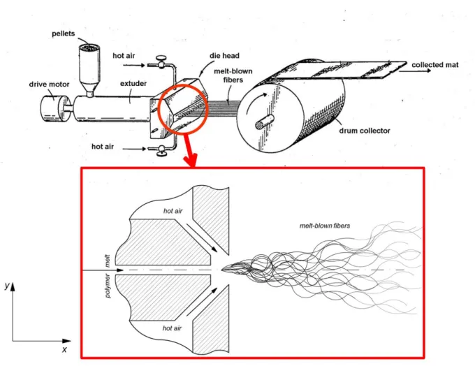
like electrospinning, melt blowing is now one of the fastest growing, high throughput and most modern methods of manufacturing of sub-micron and nano fiber mats. A typical melt blowing setup (Figure 1) consists of four main parts, which are: an extruder, melt blowing die head, hot air feed and a collector that comprises a drum, continuous band or a fixed part.
Figure 1. Schematic of a typical melt blowing system 73 and illustration of the melt blowing fiber formation at the die
A broad range of polymers and polymer blends are compatible with melt blowing. In order to obtain MB fibers, the molecular weight (Mw) associated with the melt flow index (MFI) [g/10 min]
needs to be proper. The most common polymers for melt blowing are polyolefins (especially PP) due to their physical properties, ease of processing, low cost and versatility in making a wide range
12
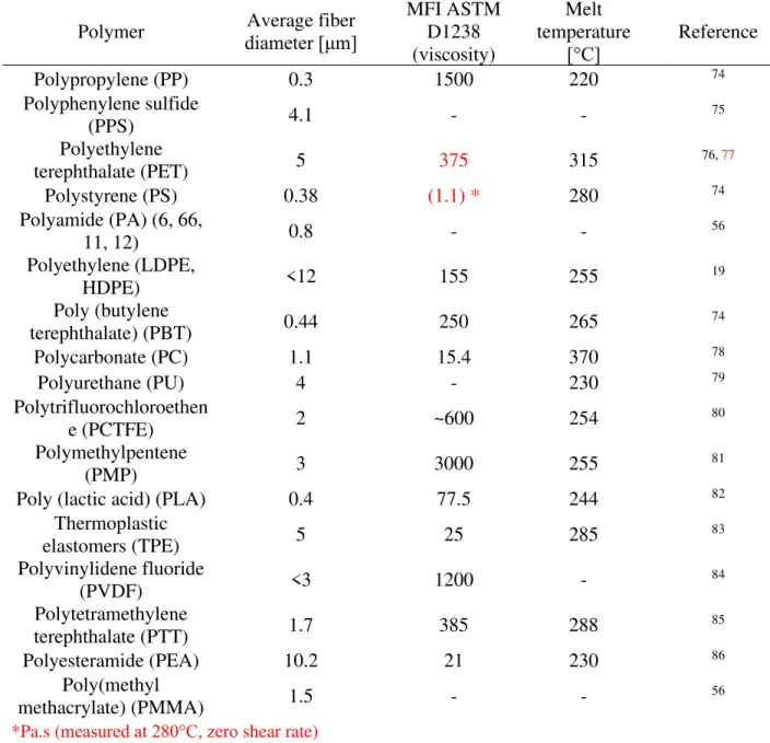
of products. Polymers commonly used to produce micro/nano fibers by using MB technology are given in Table 2 with details.
Table 2. A summary of polymers and corresponding fiber diameter, melt flow index and melt temperature utilized in the melt blowing technology
Polymer Average fiber
diameter [μm]
MFI ASTM D1238 (viscosity)
Melt temperature
[°C] Reference
Polypropylene (PP) 0.3 1500 220 74
Polyphenylene sulfide
(PPS) 4.1 - - 75
Polyethylene
terephthalate (PET) 5 375 315 76, 77
Polystyrene (PS) 0.38 (1.1) * 280 74
Polyamide (PA) (6, 66,
11, 12) 0.8 - - 56
Polyethylene (LDPE,
HDPE) <12 155 255 19
Poly (butylene
terephthalate) (PBT) 0.44 250 265 74
Polycarbonate (PC) 1.1 15.4 370 78
Polyurethane (PU) 4 - 230 79
Polytrifluorochloroethen
e (PCTFE) 2 ~600 254 80
Polymethylpentene
(PMP) 3 3000 255 81
Poly (lactic acid) (PLA) 0.4 77.5 244 82
Thermoplastic
elastomers (TPE) 5 25 285 83
Polyvinylidene fluoride
(PVDF) <3 1200 - 84
Polytetramethylene
terephthalate (PTT) 1.7 385 288 85
Polyesteramide (PEA) 10.2 21 230 86
Poly(methyl
methacrylate) (PMMA) 1.5 - - 56
*Pa.s (measured at 280°C, zero shear rate)
In general, a low Mw corresponding to a low viscosity and a high MFI is desired, because it can lower the processing temperature and thus decrease the manufacturing cost. The low viscosity and
13
high MFI provide a more uniform web with thinner fibers in the melt blowing process due to higher attenuation applied through hot air steam. In the literature, it is suggested that the suitable range of MFI for polymers used in melt blowing is 15-3,000 g/10 min 4, 56, 87, 88 as a rule of a thumb. The high polymer viscosity and i.e. low MFI yields formation of larger fibers; hence, the advantage of the process in forming ultra-fine fibers is lost 87. Besides, the average Mw and the narrow molecular weight distribution is important to obtain MB fibers. The melt flow rate of the polymeric resins depends upon the molecular weight and its distribution. The narrower molecular weight distribution renders a high melt flow rate. Lower viscosity is an essential requirement of the polymeric resins used in melt blowing. A narrow molecular weight distribution reduces the melt elasticity and melt strength of the polymer so that the melt stream can be drawn into fine fibers without excessive draw force 88, 89. However, a wide molecular weight distribution increases melt elasticity and melt strength and result in fiber breaks and flaws due to melt instabilities 4, 74. The decrease in elongation causes the increase in fiber diameter and fewer fiber entanglements. Tan et.
al. 90 reported that increasing melt elasticity increased the fiber diameter and decreased the coefficient of variation (CV) (also known as normalized width of the fiber diameter distribution) while increasing viscosity did not significantly affect the CV. Drabek and Zatloukal 91 reported that polymer molecules chain branching could lower the CV of fiber diameter distribution, while they stated chain branching did not significantly influence the average fiber diameter. In general, decreasing molecular weight or increasing melt temperature increases (e.g., due to the decreasing reptation-mode relaxation time) the CV of fiber diameter distribution. They also found that the CV of fiber diameter distribution significantly decreases due to the extensional strain hardening at the post die zone 92. They stated that increased strain hardening in uniaxial extension at post die zone
14
could withstand inhomogeneous stretching in the post-die area, which reduces CV of fiber diameter distribution.
A measure of the breadth of the molecular weight distribution is given by the ratios of molecular weight and number mass averages (𝑀𝑤
𝑀𝑛), called the polydispersity index (PDI). Jones 93 studied the influence of polydispersity on the mechanical characteristics of polypropylene (PP) MB webs. The mechanical properties of PP MB webs are slightly affected by the changes in PDI.
The strength of web decreases with the increasing degrees of PDI.
3. Processing Parameters Affecting the Fiber Mat Characteristics and Filtration Efficiency
Considering engineering and medical applications, MB fiber mats provide advantages of high filtration efficiency and low air resistance besides many other advantages 6, 94, 95. Thanks to the very high surface area to volume ratio, highly porous structure with moderate mechanical strength, and the high surface cohesion, the MB fiber mat filters can capture tiny particles less than a micron.
Moreover, the filtration efficiency can be improved further with optimizing processing parameters based on the requirements that can go up to less than 0.3 µm.
The filtration efficiency of the MB fiber mats highly depends on the processing parameters which directly relates the structure (e.g., fineness and evenness), pore size, strength, fiber diameter, thickness (packing density) and the air permeability (resistance) across the filter. The diameters of polymeric fibers can be drawn in the high-speed hot air in the range from nanometers to micrometers if appropriate parameters of the process are maintained. The MB fibers are susceptible to the processing parameters set, and they can either improve or drop the nonwoven
15
characteristics. Therefore, examining the suitable processing parameters is necessary for the MB fiber mat to fulfill the requirements of the related application field.
3.1. Polymer throughput rate
The polymer flow rate plays key roles in the resulting diameters of MB fibers. The polymer flow rate (throughput) at a given setup can be increased by increasing the extruder screw speed.
Increasing polymer throughput rate while keeping the other processing conditions unchanged results in an increase in the average fiber diameter 96. It is because the same drag force from the air jet acts on a higher polymer mass. In general, increasing polymer flow rate can increase the fiber diameter and that in turn gives a coarser fiber morphology and decrease of quality of the MB fiber mat. Zhang et. al. 97 found that increasing polymer throughput rate from 03 g/h/m to 1.5 g/h/m increased the Poly (trimethylene terephthalate) (PTT) MB fiber diameter around 20%.
Xu and Wang 95 reported that air permeability, fiber diameter, area density and surface density unevenness of PP fiber mats increases with increasing the polymer throughput rate. They stated that increase in the air permeability is due to the increased fiber diameter and it leads to big pore sizes between the fibers, therefore it results in a good air permeability of the PP fiber mats.
Typically for MB fiber mats with all the other conditions being same, increasing polymer throughput rate tends to increase fiber diameter and obviously the areal density. Increasing the throughput rate causes broader fiber diameter distributions and a coarse fiber morphology (e.g.
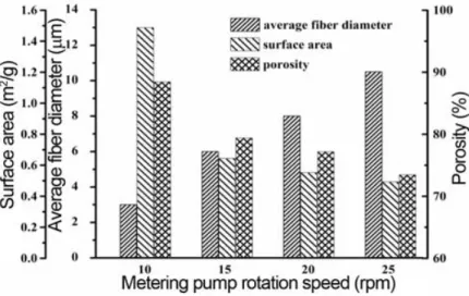
defect formation, larger pores and larger basis weight), which is unfavorable 98, 99. Guo et. al.100 demonstrated that increasing polymer throughput rate increases PP (MFI= 1200 g/10 min
@230 °C, 2.16 kg) fiber diameter from 3 to 10.5 µm while porosity and surface are decreases from 90% to 75% and 1.5 m2/g to 0.5 m2/g (Figure 2).
16
Figure 2. Influence of polymer throughput rate on PP fiber mat porosity and surface area and average fiber diameter 100
Marla and Shambaugh 101 concluded that lower polymer flow rates results in smaller fibers that causes the rapid cooling of MB isotactic polypropylene (iPP) fibers (MFI= 88 g/10 min @230 °C, 2.16 kg). It is because of the lower thermal inertia of the thinner fibers increases the cooling rate.
On the other hand, a lower polymer feed rate provides longer residence time in the extruder, which might cause the thermal degradation of the polymer. Nevertheless, various research groups reported that a decrease in the polymer flow rate leads to obtaining thinner fibers 96, 102
3.2. Air Pressure (Air flow rate or Air velocity)
Air pressure and air velocity, which are related to the air flow rate, influence the morphology.
In melt blowing, a higher air velocity results in a higher attenuation and a smaller fiber diameter.
The compressed hot air used in melt blowing was revealed to be the major energy cost. Using very high air velocity might result in a fiber break up and short, fragmented fibers. And this defect is often called fly. It occurs because of the strong cooling effect on the thinned fibers 81. In contrary, at too low air velocities, the polymer mostly would not form a fibrous mat but would fuse into a film-like body on the collector 103. The increase of the air velocity, usually achieved by increasing
17
the air pressure, can break up fibers and generate fiber loose. It was reported that such instabilities cause the fiber jet break by the increase of air pressure. 74. Drabek and Zatloukal104 summarized these flow instabilities and defect formation mechanisms at the melt blowing process. We refer the reader to their study for an in-depth understanding of such phenomenon, including whipping, die drool, onset fiber breakup, melt spraying, flies, shots, jam, etc.
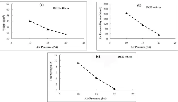
Yeşil 105 reported that increasing air pressure decreases the basis weight and air permeability of TPU MB fiber mats (Figure 3 (a)-(b)). Decreasing basis weight can be associated with the reduced fiber diameter with increased air drawing rate. In general, the lower air permeability translates to higher filtration efficiency, which means less particle and fluid to pass through the filtering media. Besides, he reported that tear strength decreased with increasing air pressure (Figure 3 (c)) due to the air quenching, which reduces fiber to fiber bond strength.
Figure 3. Effect of air pressure on the MB fiber mat (a) basis weight, (b) air permeability and (c) tear strength (DCD: die-to-collector distance)105
18
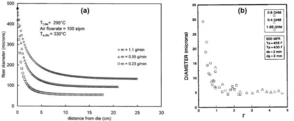
Milligan and Haynes 106 worked on melt blowing of a different types of PP (MFI varied between 500-900 g/10 min @230 °C, 2.16 kg). They reported that a ratio of air to polymer mass fluxes (Γ) provides an approximate description of the fiber size for a wide range of processing conditions (Eqs. 3). They found that increasing Γ results in a decrease in the average fiber diameter of the MB fiber, as shown in Figure 4.
𝛤 =𝑄̇𝑄̇𝑎𝑝⁄𝐴𝑎𝑒
𝐴𝑝𝑒
⁄ (3)
where, 𝑄̇𝑎 is the air flow rate [m3/s], 𝐴𝑎𝑒 is the air outlet area [m2], 𝑄̇𝑝 is the polymer flow rate [m3/s] and 𝐴𝑝𝑒 is the polymer melt outlet area [m2]. On the other hand, increasing Γ broadens the fiber diameter distribution’s CV due to the increase in the turbulence of the air flow field. But, the fluctuation of air flow (turbulence) can decrease the evenness of the MB fiber mat 107.
Figure 4. (a) The effect of polymer flow rate on fiber attenuation 101and (b) the average fiber diameter versus air to mass ratio for three throughputs 106
Higher air velocity attenuates the fibers more since the air exerts a higher forwarding drag force on the fibers. Uppal et al. 108 reported that the average diameter of the PP fibers produced by melt
19
blowing pilot line reduced by about 70 nm (from 590 nm to 520 nm) with the increase of air flow pressure from 70 to 140 kPa in the case of the die used. Milligan et al. 109 worked on the influence of an additional unheated air flow namely crossflow on the MB fiber morphology. They used two crossflow chambers placed parallel next to the melt blowing die. In their study, the influence of various crossflow angle, which is between spinline and slit (e.g.,45°, 20°, 10°), were investigated. They concluded that applying a crossflow can decrease the average fiber diameter of MB hPP (MFI= 800 g/10 min @230 °C, 2.16 kg) fibers around 45% (from ~11 μm to ~6 μm) when the slit angle was 20°. Xie et al. 107 concluded that the air velocity attenuates the fibers in their molten state. Otherwise, there is no contribution of high air velocity to fiber attenuation after the fiber solidified. Therefore, the further increase in air velocity can cool the fiber faster and hence, the attenuation process slows.
However, higher air pressure can translate air flow regime from laminar to turbulence, and further increasing air velocity could increase the CV of fiber diameter, which is unfavorable 110,
111. Tan et. al. 90 reported that increasing airflow rate from ~147 l/min to ~272 l/min increased the CV of fiber diameter from 10% to 20% while the fiber diameter decreased around 40%. Choi et al. 112 found that the stiffness of the different grade homopolypropylene (hPP) (MFI= 300-35-12.7 g/10 min @230 °C, 2.16 kg) MB fiber webs decreased as the air pressure increased. They also reported that increase in the air pressure causes a reduction in both fiber diameter and inter filament (fiber fuse) bonding.
The hydrostatic head is another factor: the measure of fiber mat resistance against the liquid pressure. When the fiber mat hydrostatic head is high, it translates to a greater barrier to liquid penetration. With this regard, a high hydrostatic head means small pores and thin fibers in the fiber mat structure, indicating favorable physical properties. Yesil and Bhat39 found that when the air
20
pressure is increased from 20 to 35 kPa, the mean flow pore diameter and air permeability decrease, and they reported the reduction could be attributed to the fiber diameter (Figure 5) that also decreases with increasing air pressure. However, they did not find a significant change in air permeability and mean pore diameter for the further increase in air pressure. In addition to these, increasing air pressure from 20 to 35 kPa resulted in the increasing of the hydrostatic head of fiber mats in a range between 54 and 97%. And they reported a slight decrease in the hydrostatic head with a further increase in air pressure. Decrease in the average pore size translates the increasing resistance of the fiber mat against fluids, so the penetration or passing of the fluid through the fiber mat media becomes hindered. As a result, the hydrostatic head of the fiber mat was increased.
Figure 5. SEM images of PE MB fiber mats produced at various air pressure; (a) 20 kPa, (b) 35 kPa, (c) 70 kPa (red-colored scale bars on the bottom left of the figures represent 20 µm) 5
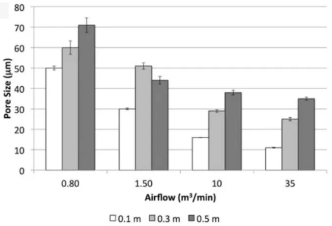
Bresee et. al. 113 reported that increasing air pressure reduces the size and the number of pores in MB fiber mats. Increasing air velocity also reduces the aspect ratio of pores. The reduction in pore size is attributed to the decrease in fiber entanglements and to the reduced fiber diameter as the airflow increases. Hammonds et. al. 82 studied the influence of air flow rate (i.e. air pressure) and DCD on the pore size distribution of the PLA MB micro and nano fiber mats. They found that increasing air flow rate and decreasing the DCD reduced the pore size of PLA fiber mat as shown in Figure 6. They also reported that the tensile strength of the PLA microfiber and nanofiber mats
21
increased with increasing airflow. Increased tensile strength of the PLA fiber mat is associated with the preferred molecular orientation by large air attenuation and fiber orientation onto the collector.
In general, MB fiber mat thickness decreases with increasing air pressure. A decrease in fiber diameter with increasing air pressure results in longer collection times in order to achieve the same basis weight. Long collection time translates more fibers and so thicker layers. With increasing air pressure, this phenomenon causes decreasing mat thickness and makes smaller pores with higher packing density 1, 82.
Figure 6. Variation of the mean pore size with respect to air flow rate and DCD 82
Tyagi and Shambaugh 114 studied oscillating (whipping) air jets to produce PP (MFI = 75 g/10 min @230 °C, 2.16 kg) fibers by melt blowing. They found that oscillating air jets resulted in finer fibers than those produced by using the classical, steady air jets. The attenuation of molten fiber jets in supersonic airflow created by a de Laval nozzle is effective for fine fiber production via melt blowing 107. Tan et al. 115 studied the effect of increasing inlet air pressure in the melt blowing die and the effect of a de Laval nozzle attached to the die face. Increasing air inlet pressure leads to a transition from subsonic to the supersonic flow at inlet pressures greater than approximately 1 bar. However, they observed that the de Laval nozzle's use suppresses compression waves
22
sourced by the unstable airflow field that causes defect formation (e.g. fly) up to certain air pressure. The corresponding centerline air velocity increases with increasing air pressure until reaching supersonic flow where the fiber spinline begins to oscillate. This phenomenon can lead to defects and probably significant whipping of the fiber jet. Violent vibrations can cause fiber breakage, shots and sticking 74. However, Xie et al. 116 reported that the spiral path of whipping close to the die plays an important role in fiber attenuation. In general, increasing the air velocity can reduce the average MB fiber diameter. But it has not been favored by industries since it significantly increases the cost of production.
The air pressure controls the fiber attenuation mechanism, the entanglements, the uniformity and also influences the defects of the fiber mats 117. Besides, the higher air velocity can lead to faster cooling of the forming fibers. A slight decrease in the crystalline fraction of the MB fibers is expected in the case of semi-crystalline polymers due to the rapid cooling of the polymeric fibers as a nature of the melt blowing techniques 76, 118. Higher air pressures were mostly suggested in the literature to achieve thinner fibers. However, air pressure has to be carefully controlled since higher air velocity can cause breakage of the spin-line and result in shot, fly imperfection and relatively larger fiber diameters due to fiber fuse 119.
3.3.The Effect of Melt and Air Temperature
Increasing air temperature and melt temperature leads to a reduced polymer viscosity which increases the attenuation. The air drag generates a higher stretching on the polymer between the processing temperature and the solidification temperature (crystallization temperature for semi- crystalline polymers that are typically used at melt blowing). In general, the higher temperatures are not favorable in melt blowing with respect to the degradation of the polymer. In this regard, Drabek et. al.120 reported that an hour of residence time at the processing temperature (combined
23
with medium high shear rate level) resulted in nearly 40% decrease in the PP resin’s (MFI = 1200 g/10 min at 230 °C, 2.16 kg) molecular weight due to chain scission. Lee and Wadsworth 121 demonstrated that increasing the air temperature from roughly 210 °C to 240 °C led to a nearly 50% reduction in the average fiber diameter of iPP (MFI = 700 g/10 min @230 °C, 2.16 kg), where the smallest fiber diameter they obtained was around 5 μm.
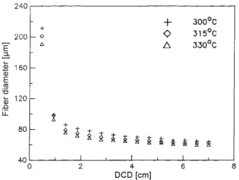
Bansal and Shambaugh 102 carried out a series of melt blowing experiments of PP (MFI = 75 g/10 min @230 °C, 2.16 kg) at different air temperatures with an experimental melt blowing slot die. Their results show that increasing the air temperature causes an increase in the attenuation rate of the fiber and produces a finer fiber (71.7 µm →62.5 µm) as shown in Figure 7. Guo et. al. 100 investigated the relationship between the melt blowing process parameters and the PP fiber mat structure. They reported that the porosity of the PP fiber mat did not change with increasing air temperature from 300 to 330 °C in spite of the finding that increasing air temperature resulted in decreasing the average fiber diameter. On the other hand, Xie et al. 107, 122 reported that higher air temperature does not always produce fine fibers with even diameter distribution. They obtained that increasing temperature might cause thicker fibers and defect formation due to the turbulent flow by increasing air temperature. Besides, the air cools down very fast when it exits the die due to the low ambient temperature. This effect depends on the polymer melting temperature and the air-fiber temperature gradient towards the collector. Air temperature usually just slightly influences fiber morphology for high DCDs, in many cases its effect on the fiber diameter is negligible.
24
Figure 7. Change in fiber diameter as a function of DCD with air temperatures between 315-330
°C 102
Moore et al. 123 reported that the temperature of the melt blowing die (and therefore the melt) plays a crucial role in the fiber attenuation and affects the fiber diameters and pore sizes significantly. They found that increasing the die temperature from 250 °C to 300 °C decreases the average fiber diameter of the MB fibers around 50% (from 12 to 6 μm). On the other hand, Marla and Shambaugh 101 reported that the further increase in polymer temperature would result only in a slight decrease in the fiber diameter.
Yesil and Bhat 5 studied the influence of the die temperature on PE (MFI = 155 g/10 min @190
°C, 2.16 kg) fiber mat’s porosity and barrier properties. They reported that the mean pore diameter of the MB fiber mats produced at 255 °C is slightly lower (~15%) than those processed at 240 °C. However, they found that the effect of the die temperature on the air permeability is negligible. In the same study, the hydrostatic head of PE fiber mat increased by increasing the die temperature.
The higher die temperatures not only result in smaller pore diameter and higher hydrostatic head, but also finer fibers were obtained. However, Xu and Wang 95 reported that in the case of PP, increasing air temperature from 170 °C to 230 °C decreases air permeability from 1054 mm/s to
25
689 mm/s. This improvement is attributed to that finer fibers were produced at higher temperatures. During melt blowing non-isothermal crystallization occurs due to the large temperature difference between the die and ambient temperature. Lower crystallinity is expected due to rapid cooling, which causes reduced polymer chain segment motions. Therefore, the collected MB fibers exhibit relatively low crystallinity due to the effect of quenching 82.
There are no reports on achieving greatly thinner fibers by simply increasing polymer or air temperature which is possibly because of the risk that high temperature is likely to cause thermal degradation. Nevertheless, the high temperatures can be considered for producing fine fibers as long as the extra production expenses are acceptable, and there is no oxidation of the polymer occur and no defect formed e.g., fiber fuse, fiber breakage, shot, fly, etc.
3.4.The Effect of Die-to-Collector Distance (DCD)
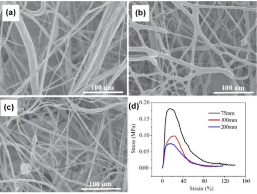
The die-to-collector distance (DCD) influences the fiber diameters since it correlates with the dwell time of the fiber attenuation. This results in changes in both the aerodynamic drag and fiber- fiber entanglements and their fused bonds. Besides, as fiber jet travels along the collector the molecules become oriented 124. The typical DCD at melt blowing is in between 50 - 500 mm.
The DCD can have various effects depending on the material due to the intrinsic properties, i.e. crystallization behavior, molecular weight, relaxation time, etc. The average diameter of the fibers produced at a greater DCD tends to decrease due to the more time of the attenuation as shown in Figure 8 106, 119, 121, 122.
26
Figure 8. Optical microscopic images of PP MB fibers produced at (a) DCD = 25 mm and (b) DCD = 50 mm 122
Increasing DCD translates the fibers travel longer distances, and that might result in an altered crystallization kinetics, e.g. change in the degree of crystallinity. However, higher DCDs may result in diminished interfiber adhesion and web strength originating from the lower fiber contact temperatures 125. Feng 126 reported that increasing DCD decreases the PLA fiber mat web strength despite the thinner fiber produced at larger DCDs as shown in Figure 9. Yesil and Bhat 19 reported increasing DCD resulted in a looser web structure and so poor mechanical properties due to reduced fiber entanglement.
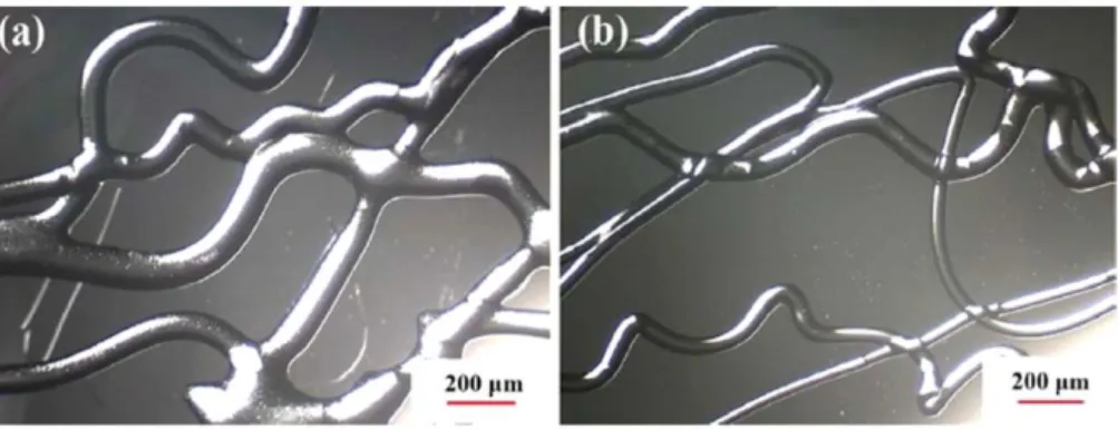
27
Figure 9. SEM images at DCD of (a) 75mm, (b),100mm (c) 200mm and (d) stress–strain curve of the PLA fiber mats collected at various DCDs 126
Increasing DCD results in fiber collection over a wider area. It also results in a softer, fluffier structure, so increasing DCD decreased fiber mat solidity 95, 127. The effect of the increased deposition area is smaller than the effect of decreased fiber mat solidity and that results in a thicker fiber mat. The mat thickness correlates to the packing density, which is a crucial factor in determining the pore size. Denser fiber packing can be reached with a thicker layer of fibers that will result in higher efficiency of the filter 42, 128 with an increased pressure drop. Therefore, the mat thickness and packing density has to be optimized and DCD is the key parameter in that.
Slightly finer fibers at higher DCD can be obtained due to the deformation of hot uncrystallized fibers 108. Chen et al. 129 obtained that PBT (MFI = 62 g/10 min @ 250°C, 2.16 kg) fiber diameter decreases 13% as the DCD increase from 100 to 140 mm. However, they reported that the fiber diameter only decreases slightly when the DCD is larger than that. Uppal et. al. 108 generated MB
28
PP fibers and investigated the influence of relatively large DCD (250 mm to 350 mm) on the fiber mat characteristics. They produced PP fiber mat samples with the same basis weight (~25 𝑔/𝑚2) while the mat thickness increased from 0.44 mm to 0.53 mm with increasing DCD. They found that the pore diameter decreases from 10.4 μm to 6.5 μm with an increase of DCD from 250 to 350 mm while the fiber diameter and air permeability of the fiber mats decrease slightly. The reduced pore size is related to a higher degree of fiber entanglement. This is because of the improved self- bonding of the thinner and continuous MB fibers produced for the same basis weight. As a consequence, the resistance to the penetration of liquid through the MB fiber filter media increases, and that in turn increases hydrodynamic head as shown in Figure 10. The pressure drop of the filter media first increased from 49 Pa to 55 Pa with increasing DCD then it became constant due to reduced pore size. However, the filtration efficiency is slightly improved from 80% to 82% due to the smaller pore size as well as greater specific surface area of the finer fibers produced at higher DCD. The slight increase of these properties indicates smaller pores, greater specific surface area of the thin and continuous fibers and higher degree of fiber entanglements.
Figure 10. Influence of DCD on the PP web (a) pore size and (b) hydrostatic head characteristics
108
Choi et al. 112 reported that increasing DCD improves tenacity and decreases Young’s modulus of hPP (MFI= 300-35-12.7 g/10 min @230 °C, 2.16 kg) fiber mats and results in increased
29
elongation at break. Besides, they found that an increase in DCD reduces the bonding of the fibers (fuses) without much effect on the fiber diameter. Bresee and Qureshi 130 studied the effect of DCD on the diameter MB PP (MFI = 1,259 g/10 min @230 °C, 2.16 kg) fibers with commercial and experimental melt blowing lines. They found that the average fiber diameter decreases with the increase of DCD, but the influence is very weak. The average fiber diameter reduced by nearly 11% for the experimental line and 15 % for the commercial line with 600 mm increase of DCD from 200 to 800 mm. They also stated that the maximum fiber diameter and its CV increase with the increase of DCD due to the fusion of fibers.
In another study, Bo 131 reported that upon increasing DCD the diameter of PP (MFI = 34.2 g/10 min @ 230°C, 2.16 kg) fibers first decreases and the attenuation stops in a certain DCD and the diameters starts increasing again (Figure 11). He stated that after this point, long time travelled fibers begin severely entangled and stick to each other and that in turn gives an increase in fiber diameter and uneven structure for very long DCDs (above 1000 mm).
Figure 11. Change in fiber diameter respect to very high DCDs 119
30
Lee and Wadsworth 121 studied the influence of processing parameters on melt blowing of iPP (MFI = 700 g/10 min @ 230°C, 2.16 kg). They reported that decreasing DCD increases the degree of fiber entanglements but does not affect the average fiber diameter. On the other hand, as the DCD increases the fibers are laid down with less air drag force and the effect of air pressure is reduced. Also, air turbulence is high at the collector drum and longer DCDs allow the fibers to be laid down over a wider area as shown in Figure 12 127. In the case of polyolefin polymer fibers like PP, lower DCD results in less time for fibers to contact each other. So, fibers become less entangled before reaching the collector. In addition to this, decreasing DCD results in increasing fiber separation in a high air flow and could turn in reducing the number of fiber entanglements
127.
Figure 12. Fiber flow in (a) horizontal (drum collector) and (b) vertical (flat conveyor belt) melt blowing line 132
Peng et al. 133, reported that increasing DCD resulted in an increase of the average diameter of MB PP (MFI= 800 g/10 min @230°C, 2.16 kg) and PP/TPU (MFI = 73 g/10 min @230°C, 2.16 kg) fibers and decreases the CV. They also found that the elastic recovery rate and bulkiness (solidity or fiber packing density) increase and softness decreases, while DCD increases. Another
31
research group reported a similar result on MB TPU fiber mats, in which fiber diameters continuously increase with increasing DCD 134. In this study, MB TPU fibers are found to be less entangled at shorter DCDs; however, the fibers collected on the rotating drum collector are oriented with increasing DCD instead of being randomly distributed as shown in Figure 13. The different fiber diameter formation and attenuation mechanisms during the melt blowing process may have been due to the differences in the thermal and elastic relaxations of TPU compared to commonly used polyolefins such as PP.
Figure 13. Distribution of the MB TPU fiber bundle orientation at various DCDs 134
The fiber formation mechanism and the fiber structure developments highly dependent on the DCD beyond doubt. In general, lower DCDs yields thicker fiber diameter and lower porosity of the MB fibers. When DCD increases, fibers undergo higher attenuation, and therefore fiber diameter and porosity decrease while too large DCDs might cause severe imperfections. However, thermoplastic elastomers exhibit phenomenologically different fiber formation mechanism considering DCD conditions due to their thermal and elastic relaxation behavior (rubbery
32
characteristics). Consequently, the structure and properties of MB fiber mats can be controlled and optimized through DCD.
4. Developments of filter media made of MB nano/microfibers for filtration
The outbreak of the coronavirus (COVID-19) pandemic revealed that respiratory protection plays a vital role in the present world and the development of ultrafine polymeric fiber mats highly efficient filters allowing filtration of a wide range of particles, viruses, and aerosol is necessary 135,
136. MB filters are the classic filtration media of good-quality masks, independent from the pandemic. Bioaerosols that are living or originate from living organisms might include microorganisms and fragments, toxins, and particulate waste from all varieties of living bodies 137. These biologically hazardous substances or bioaerosols might be transferred through the air, and they could cause severe health effects because of their ability to incubate, grow, multiply, and produce toxic substances 138. The efficient inhaled air filtration and cleaning off such hazardous particles, as well as the destruction of the inhibition of that bioaerosol development, are the matter of respiratory protection systems made of nonwovens filters. Many particulate respirators use a filter media made of MB fiber mats to capture these types of particles. We summarized the MB fiber mats and related properties in Table 3 reported for high-efficiency fiber mats produced via melt blowing technology.
Table 3. Some essential filtration properties of MB fiber mat filter medias reported in the literature
Material
Average fiber diameter
[µm]
Average pore size
[µm]
Porosity [%]
Pressure drop [Pa]
(loading speed)
Filtration efficiency
[%]
Reference
PP 0.55 6.5 N/A 54.9 (32
L/min) 81.9 108
33
PP 2.8 N/A 85.6 55.9 (0.053
m/s) 88.6 139
PP 2.4 9.3 N/A 37.4 95.91 46
2 layers PP MB + 3 layers
PP Needle Punched (NP)
2.07 (MB) 15.5 (MB)
N/A 136.87 (85
L/min) 99.52 140
17.9 (NP) 70.1 (NP)
PP 0.47 N/A N/A 20.27 (0.05
m/s) 91.19 141
0.5 wt% MgSt
additive PP 1.63 ~15 89.3 82.32 (85
L/min) 99.03 142
1 wt% MgSt
additive PP ~2 14.2 90.1 53.1 (85
L/min) 92.57 143
PP MB +
PVA ES 0.208 N/A N/A 34 (3.4
m3/h) 96.5 144
PP / PS 3 ~9 ~90 37.73 (32
L/ min) 99.87 94
Spunbond (PET/PE) / +
TiO2/Ag additive MB
PP
4-16 3.3-3.8 N/A ~80 (85 L/
min) ~ 95 52
PP 2.64 ~17 N/A
22.45 (0.053 m/s)
@50 °C 98.46
145
19.45 (0.053 m/s)
@110 °C ~60
PP 2.1 11.2 89 120 (0.141
m/s) 99.65 146
PP / PEG 1-6 N/A 88 55.53
(0.053 m/s) 85.33 147
PP 1–2 3-14 89.94 38.7 (32
L/min) 98.35 8
10 %wt BaTiO3
additive PP
~3 N/A 65 95 (0.053
m/s) 99.97 148
3 wt% TiO2
additive PP 6.73 N/A N/A 40 (85 L/
min) 96.32 149
PP / PC 0.63 N/A N/A 59 (3.4
m3/h) 95.9 150
34
PLA 0.1–3.0 N/A N/A 40.8 (0.053
m/s) 88.5 151
PLA / PCL 3.3 N/A N/A N/A (0.053
m/s) 95 152
PLA 3.1 N/A 88.5 38.2 (0.053
m/s) 93.2 139
In order to fulfill various requirements considering an efficient filtration, multi-layer or laminated filtering systems are preferred, in which every layer meets different tasks. The MB fiber mats are often used as stacks that consists of several layers of the separate fiber mats and stacking of layers with another woven or nonwoven or a film 153, 154. The additional layer for the filter is selected to impart additional or complementary properties to fulfill required features, such as tear resistance, strength, biocompatibility, air permeability and filtration properties. The laminated structures are highly suitable not only for respiratory devices but also for various application field including protective garments, drapes, medical gowns, covers for diapers, adult care products, sanitary napkins, etc. 155.
Roh et. al. 156 prepared and tested the filtration efficiency of multi-layered nonwoven filters made of electret PP MB fiber mat and PET nonwoven to lower the pressure drop, improve the quality and extend the service life for various filtration application. In their study, various filters were constructed with and without an air gap between the layers either by inserting a 5 mm thick acrylic plate (Air gap) or 5.5 mm thick-spacer web (S-gap) (Figure 14). The pressure drop across the filter media is a function of the particle loading speed; when loading speed increases, pressure drop increases. They reported that pressure drop decreases dramatically with NaCI particle loading when the air gap is inserted between layers. The designed air gap acted as the active flow channel between fiber mat stacks. However, the pressure drop with the loading did not effectively reduce
35
even increased for the tested the two layers construction spacer web inserted filter because of the thick spacer web inhibited airflow.
Figure 14. Schematic overview of the study (a) Filtering media layer construction, (b) Pressure drops of different layer-constructions for face velocity of 15 cm/s, (c) computational model for
the pressure drop behavior of different stack and (d) Filter media morphology of different constructions after NaCI aerosol loading 156
For the four-layer constructions, either the air gap or the spacer web insertion is found beneficial in reducing the pressure drop. Even, the effect was more significant when the loading velocity increased from 15 to 20 m/s. They obtained that spacer web insertion between the filter layers is more effective in reducing the pressure drop compared to using bulk air gap. Results obtained by the researchers showed that the inserted spacer web took place effectively distributing the airflow and pressure drop over the filter media because the thick spacer web acted as a direct airflow channel. A significant change in filtration efficiency and pressure drop occurs when the solid particles are accumulated inside a fiber mat medium. The pores of the fiber mats could be clogged with increasing pressure drop by the dendritic structure forming due to the captured solid particles.
This is related to the pressure drop development, which goes faster for the solid aerosol particles
36
compared to the liquid aerosol of the filtering media 45. They reported that layered filter design delays the clogging compared to the single layer MB fiber mats. However, increasing NaCI aerosol particle loading velocity from 15 cm/s to 20 cm/s increased the pressure drop and resulted in faster clogging of the filtering media. On the other hand, four-layered stacks showed promising results that successfully lowered the pressure drop and increased the service life of filter media by inserting either a spacer web or bulk air gap. Their results showed that the four-layered web spacer gap design has the most effective load share of solid particles via the uniform airflow distribution, besides no particle appeared in the bottom 4th layer (Figure 15). Furthermore, they determined that the four-layered web spacer gap design the loaded NaCI particles are shared from the 1st, 2nd, and 3rd MB layers with 87.7%, 9%, 3.3%, respectively.
Figure 15. Four-layered stacks with spacer webs; (a) 1st MB layer (b) 1st spacer web layer, (c) 2nd MB layer, (d) 2nd spacer web layer, (e) 3rd MB layer, (f) 3rd spacer web layer, (g) 4th MB
layer 156
Li et. 144 developed a hierarchical fibrous structure made of PP MB and polyvinyl alcohol (PVA)/zeolite imidazole (ZIF) electrospun (ES) fibers. They produced PP MB and PVA/ZIF ES fiber mats separately, then they compressed the fiber mats to obtain composite fibrous structure.
37
The average fiber diameter of the hierarchical fibrous structure was around 0.209±0.058 µm in the most successive case. They observed that the hierarchical PM2.5 filtration performance improved to 96.5% while the pristine PP MB fiber mat had 21%. The hierarchical filter structure with finer fibers effectively intercepts the particles to acquire better adsorption, resulting in improved filtration efficiency. They also reported that composite filter media had higher tensile strength than that of the pristine fiber mats. This is associated with high friction and good fiber adhesion between the MB and ES fiber mats.
PP is the most widely used polymer for producing MB fiber mats 96 because of the fair mechanical properties and cheap price. It is a non-polar polymer having a very large band gap above 8 eV, which makes PP fiber mat a good electric insulator. This also makes PP less attractive for capturing tiny particles that is clearly a disadvantage. Admixing various charge enhancer additives (e.g., barium titanate, stearate, calcium carbonate, etc.) are suggested to overcome this issue and hence improve the filtration performance 148, 157. In addition, environmental conditions (e.g., air humidity, moisture) and applied decontamination methods (e.g., sanitizing with alcohol) may favor the degradation of the charge that reduces filtration performance 158. Therefore, the ability to maintain charges is fundamental for various in-use scenarios such as in respiratory protective devices 27. Electrostatic charging is frequently applied to nonwoven filters to enhance their tendency to capture smaller microorganisms. This is typical for particles smaller than a micron that can potentially penetrate into the respiratory system 159, 160. These systems involving charged filter media are often called electret filters. Imparting electrostatic charge on the filter medium has been successfully applied in the last three decades to the fiber mats to improve filtration characteristics without compromising other properties (e.g., dimension and structure).
Particularly, the ionic species generated by the negative polarity through the corona-charging is