Human Behavior Model Based Control Program for ACC Mobile Robot
Claudiu Pozna, Fritz Troester
University Transilvania Brasov, Romania, cp@unitbv.ro
University of Applied Science Heilbronn, Germany, troester@hs-heilbronn.de
Abstract: Present work is a part of the ACC autonomous car project. This paper will focus on the control program architecture. To design this architecture we will start from the human driver behavior model. Using this model we have constructed a three level control program. Preliminary results are presented.
Keywords: Control Program, Behavior model, Autonomous car, Mobile robot
1 Introduction
One of the main projects of Applied Sciences University Heilbronn, Germany is named ‘The Automotive Competence Centre (ACC)’. The aim of this project is to improve knowledge in the field of the car locomotion control engineering. More precisely, we intend to develop control algorithms which can be used to control an entire autonomous car. To achieve our purpose, we have transformed a car into a mobile robot [16], [17]. Knowing several results from this area ([9]...[14]), this development is made on the background of our institution’s (University of Applied Sciences Heilbronn) main aim: the education of the future engineer.
Based on these remarks, we briefly sum up our conclusions concerning the developments of autonomous cars:
- Robust and intelligent algorithms have been developed to control an autonomous car. These algorithms involve a high level of mathematical resource, which must be implemented in real time applications;
- There are many projects made by powerful car companies. The results of these projects are: ‘it can be done but it is too expensive’, moreover, much knowledge of these projects can be used in the development of new systems;
After these conclusions, it is important to mention what kinds of benefit can be expected from our project. We can sum these up as follows:
- Information which will be used in the education of the future engineers by the University Heilbronn,
- Information about the design of a low price driving robot,
- Information about the implementations of high level control algorithms in real time applications,
- Development, design and testing of simple manoeuvres in real car driving like parking, etc.
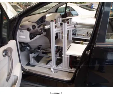
In [16] we have presented the mechanical and electronically construction of the ACC mobile robot (see Figure 1).
Figure 1 The driving robot
The structure of the robot is presented in Figure 2 where the actuators (rectangles) and the sensors (circles) of the driving robot are plotted. More precisely: 1 is the actuator or the sensor for braking subsystem; 2 is the actuator or the sensor for steering subsystem; 3 is the actuator or the sensor for the gear level; 4 is the actuator respectively the sensor for ignition key; 5 is the actuator or the sensor for the gas; 6 is the ultrasonic sensor; 7 is the GPS. The robot ECU is the Electronic Control Unit which control the robot via CAN bus. In fact we replace the human driver by a mechatronic structure which is able to recognize the environment (with the extra sensors: ultrasonic sensor, GPS, etc.) and to drive the car (with the mentioned actuators, sensors and with the car ECU’s).
Figure 2 The robot structure
The next level in our project was to imagine and implement the soft which will control the robot under changeable driving circumstances. Present work focuses on the control program architecture design. The idea is to imagine architecture based on human driver decisions model.
2 The Driver’s Behaviour Model
Some discussions about other ideas are necessary. From the references ([1]...[8]) we know that the ‘Driver’s Behaviour’ model is used in the simulation field [3], [4] and also in autonomous or mixed manual and autonomous field [2]. The first researches on the subject started in 1950 [3] and began with the ‘Skill-based driving model’, continued with the ‘Motivational model’ which considers the drivers emotional state (from this class we can enumerate the ‘Risk compensation’; ‘Risk avoidance’ and ‘Risk threshold models’) and in the last years is developed in a ‘Hierarchical control structure’ (by Milchon). The
‘Hierarchical control structure’ divides driving into three levels of control: a strategic level which establishes the goal of the driving; a tactical level which finds the solution to accomplish the goal; an operational level that implements this solution on the low level control of the vehicle. Behind this ‘Hierarchical control structure’ many scientific papers consider and develop problems like:
‘Longitudinal behaviours models’ [2]; ‘Lateral behaviours model’ [5], [1]; ‘Brake behaviour’ [2] etc. The solutions of these problems are varied: ‘Linear optimal Control’, ‘Heuristic human driver models’, ‘Adaptive control strategy’, ‘Neuronal Network and fuzzy logic’, ‘Mental models’, etc.
Because we intended to make a heuristic approach, we were interested to find control programs architectures which model the human behaviour. Such architecture is presented in [3] and [4]. Some conclusions about these briefly overviews are the following:
Robot ECU
1 2
3
1 2
3
5
4 4
5 7
Car ECU
In the scientific literature referring to ‘Driver Behaviour Model’ we have found several results which can be adapted and used in the ACC robot control;
Recent works accept the Milchon three levels architecture;
Many papers are focusing in developing the tactical level where the program must find the solutions in condition of changeable driving circumstance.
Model design is a possible solution of this problem. In this case the model is the
‘human driver behaviour’. Our idea starts from this point: we consider that is more suitable to model, and implement the ‘human driver decisions act’ than the
‘human driver actions’.
To obtain the model of human driver behaviour a preliminary analyze must answer to the following questions: ‘how a common driver acts, or what is a driving behaviour?’; ‘can we obtain some fundamental true about this behaviour and use them in our construction?’ and more ‘can we identify tools to transpose this behaviour in soft?’
To answer to the first question we must give the definition of the ‘behaviour’ by underlining the semantic characteristics of ‘Driving behaviour’. First it is important to establish the category tree of this word: from [15] we have {act → activity → (behaviour, practice,...)}. According to this the behaviour is: ‘an action or a set of actions performed by a person under specified circumstances that reveal some skill, knowledge or attitude’. From the scientific literature which concern the driving behaviour ([1]...[8]) and from our experience the driving behaviour has a special character. To describe this character we focus on the word
‘custom’ which is from the same category tree {act → activity → practice → custom,.} and which is defined like: ‘accepted or habitual practice’. In many situations these customs have a special nature: automatism: any reaction that occurs automatically without conscious thought or reflection. Now we can present what we understand by ‘Driving Behaviour’: an action or a set of actions performed by a person under driving circumstances, action which tend to be transformed in customs and even in automatisms; in fact the ‘Driving Behaviour’
is composed from a collection of behaviours (the driver’s behaviour when he makes the ignition, the driver’s behaviour when he stops the car, ...).
From the same theoretical and practical research, we establish the following
‘fundamental truth’ for the ‘Driving Behaviour’:
1 A priori the driver establishes the current driving goal;
2 A behaviour is a set of actions;
3 These behaviours are linked together creating a system which allows to obtain solutions in the driving circumstance;
4 The translation from one behaviour to other is triggered by brow casting an event;
5 This system is developed by learning - experience;
6 Behaviours presume decisions with an incomplete set of information;
7 In time, these set of actions tend to be transformed in customs and automatisms.
These propositions are in accord with the well known three level architecture of Milchon: the strategically level where the driver establishes his goal, the tactical level where the driver finds the solution to accomplish the goal and the operational level where the driver implements these solutions. Using these propositions we can focus on the tactical level and model (approximate) the ‘Human Driving Behaviour’ by a collection of high linked programs (behaviours) which are stored in a memory. The decision to run a certain program is made by a manager program. This decision is based on the goal of driving and acknowledging about the environment (driving circumstance). Each program (behaviour) is a succession of instructions (action) which impose parameters and trigger actuators. For a better understanding of this concept we will compare it with the well know Lego toys concept where several buildings (goals) can be made (solve the driving circumstance) using a finite type of bricks (program - behaviour). Using this analogy we will underline that it is very important to provide the interconnections of the bricks, and have an appropriate collection of them.
In what concerns the soft implementation, starting from these seven propositions, we can imagine the utility of state machine for handling the behaviours, fuzzy logic to enable the decisions based on incomplete information, or in describing the environment, and neuronal network to implement the learning processes.
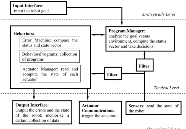
After we have answer to the analyze questions a graphical representation of all these results will make our concept more understandable (see Figure 3)
Some explanations are necessary:
- The strategically level, where the robot must compute his goal is replaced with an interface where the human operator imposes the goal;
- The ‘Program Manager’ analyzes the goal in the driving circumstances which are obtained from the sensors; the result of this process is the status vector of the robot (the desired position, velocity, etc.) and the decision to run certain program from the ‘Behaviours’ subsystem;
- The ‘Behaviours’ are composed by three parts:
o The ‘Error Machine’ which compares the status vector with state vector (the positions, velocity, etc. obtained from the sensors);
o The ‘Behaviours Programs’: is a collection of programs (bricks);
each program is able to solve a special environment situation (ignition, emergency stop, zero position, errors....);
o The ‘Actuators Manager’ which manage the actuators of the robot;
- The ‘Output Interface’ allows to the human operator to read the state vector and the errors of the robot and also memorizes the robot state history;
- The ‘Actuators Communications’ outputs data to the microcontrollers of each actuator.
Figure 3 The program architecture
To build the ‘Behaviours’ subsystem it is important to imagine the structure of the programs (bricks). Understanding that this subsystem can, and will, be enriched in Figure 4 we propose three different structures, named: ‘basic behaviours’, ‘error behaviour’ and ‘simple behaviour’. The main differences between these bricks are the connection type (P previous, N next, E error, QI quick in, QO quick out) and also the direction of information flow.
Program Manager:
analyze the goal versus
environment, compute the status vector and take decisions Behaviors:
BehaviorsPrograms: collection of programs
Error Machine: compare the status and state vector
Actuator Manager: read and compute the state of each actuator
Sensors: read the state of the robot
Actuator
Communications:
trigger the actuators Input Interface:
input the robot goal
Output Interface:
Output the errors and the state of the robot; memorize a certain collection of data
Strategically Level
Tactical Level
Operational Level Filter
Filter
Figure 4
The behaviors structure (bricks)
In the ‘Behaviours’ subsystem an ‘Error Machine’ program is running. The aim of this program is to compare de ‘status vector’ (the desired variable of the robot: car speed, steering angle etc.) with the ‘state vector’ (the real variable read from the sensors: car speed, steering angle etc.). The decisions, about which brick must be connected, are made by the ‘Program Manager’. This program compares the goal of the robot with the driving circumstance; establishes the status vector and enables the brick which must run. After these decisions the program continues to compare the robot goal with driving circumstance. If the result is acceptable, nothing is changed (the same brick is run), in contrary, a ‘Crisis’ or a ‘Failure’
event is broadcast. ‘Crisis’ means that a new behaviour is needed, so the status vector as well as the brick is changed. ‘Failure’ means that we don’t have solutions (behaviours) to solve the problem and we must stop safely the robot. We present these processes using the diagram from Figure 5.
Conclusions about the program architecture are necessary:
The structure of the program is a Milchon type structure;
In this case the goal of the robot is imposed by the human operator via the
‘Input interface’;
The tactical level finds solution, linking several programs (bricks). A brick is a succession of action; an action sets up parameters and trigger actuators;
The human behaviour approximation consist in modelling the human decision process and not the human acting process;
There are two control loops:
o A high level control solved by the ‘Manager Program’: goal versus robot performance;
Action 1 E
Action N
Basic behavior Error behavior
Action 1
E
Action N
Action 1
E
Action N
QIn QO
Simple behavior
o Operational level control, low level control solved by each actuator microcontroller, desired value versus current value.
Figure 5
The Program Manager structure
3 Preliminary Results
This paper presents only partial results on our control program construction. The control program is made in Matlab and use the xPC toolbox. In order to interact via CAN with the already made mechanical and electronically parts we have started by creating the communication tools (see Figure 6). Using these tools we have created the operational level.
OK
CRISIS
FAILURE Continue to run
the brick
Stop the Robot
Establish the status vector
Establish the brick which will be run
Establish the parameters of the brick Robot Goal
Driving Circumstance
Figure 6
The ACC Robot communication library
In order to implement the ‘Behaviours’ structure in MATLAB we choose the
‘Stateflow’ toolbox. Some result is presented in Figure 7 where the three subsystems ‘Error Machine’, ‘Behaviours’ and ‘Actuators Manager’ are captured.
The ‘Error Machine’ checks element by element the relation between the state and status vector. In the ‘Behaviours Programs’ are (in this stage of development) for bricks:
‘Basic Behaviours’: Initialization of actuators (the aim of this program is to enable the MAXXON actuators); Start (start the ignition of the car, and to change the gear level position from P to D); ZeroGo (put in zero position all the actuators: release the gas pedal; brake the car; turn the steer in position zero, change the gear level into position P; turn off the ignition key);
‘Error Behaviours’: ZeroE (put in the zero position all the actuators when an error event is brow cast).
These bricks build up a linked structure. In actual state of development the bricks are connected in a statically structure, the only possibility that the information flow change is an error event. Because the connections between the brick are already created, the aim of the future ‘Program Manager’ will be to enable the appropriate connection between the bricks.
The MAXXON communication library
The MAXXON Steering library The ACC Robot communication library
The ‘Actuators Manager’ it is a parallel structure which permit the parallel use of all the actuators.
Ma si nae roarE
1
Ex ec uti E
3
Gand irE
2
WaiT
Sta i Ero arE
e ntry: Con tE=C on tE +c on tE , ER ROR Ve rifica_E ro area
ZeroG O
Sta rT En ea bl E
U ra t or uL ZeroE
Ch eiE
1
Cu tiE
2
Vo l aN
3
Fra nA
4
{co ntE=0}
[co ntE==0 ]
Ve rifica Da
{Da }
Figure 7
The actual state of construction of the ‘Behaviours’
The control program is plotted in Figure 8. In this picture it can be seen the connection between the state machine (‘Behaviours’) and the subsystems from the operational level named ‘Sensor Communication’ and ‘Actuators Communication’.
“Behaviours”
Error Machine
Behaviours Programs
Actuators Manager Bricks
Figure 8
The control program made from Stateflow and Simulink objects
Conclusions
The aim of the paper was to present the control program architecture that we have imagined for the ACC mobile robot. After we have designed and realized the mechanical and electrically subsystem of the robot the next challenge was to implement the control program. Because the control task is complex, we intend to solve it approximating the human driver behaviour. More precisely we don’t intend to model how the driver is steering, pushing the gas pedal etc. Our intention is to model the driver decisions process: the human (robot) decides to brake; the human (robot) driver decides to steer etc.
In actual state of work only a part of this construction is made: de operational level and the structure of the ‘Behaviours’ (a part of the tactical level). In this system we implemented several behaviours (bricks): start the car, enable the motor, put the car in zero position, etc. Future developments are focus in the tactical level: creating new bricks, creating the program manager, the filters etc.
‘Behaviours’
“Actuators Communications”
‘Sensors Communications’
References
[1] Mizukami, R.: Development of Autonomous Ground Vehicle Design of Control System. www.ee.ualberta.ca
[2] Bengtsson, J.: Adaptive Cruise Control and Driver Modeling. Department of Automatic Control Lund Institute of Technology Lund, November 2001 [3] Al-Shihabi, T., Mourant, R.: A Framework for Modeling Human-like
Driving Behaviors for Autonomous Vehicle in Driving Simulators.
Proceedings 5th International Conference on Autonomous Agents, June 2001, 286-291
[4] Quispel, L.: Automan, a Psychologically Based Model of Human Driver.
Experimental and Work Pscychology. Department of Psychology, University of Groningen Grote Kruisstraat 2/1, 9751 MN Groningen
[5] Ungoren, A.: An Adaptive Lateral Preview Driver Model. Vehicle System Dynamic
[6] Liu, A.: Modeling and Prediction of Human Driver Behavior. Proc. of the 9th International Conference on Human Computer Interaction, Aug, 2001 [7] Huang, S.: Design and Performance Evaluation of Mixed Manual and
Automated Control Traffic. IEEE Transaction on Systems Man and Cybernetics Nov. 2000
[8] Salvucci, D.: Modeling Driver Behavior in a Cognitive Architecture. In Press, Human Factors, February 16, 2005
[9] Dobrescu, R.: Autovehicule Inteligente, Editura MATRIX ROM Bucuresti 1995
[10] Antsalkis, P.: An Introduction to Intelligent and Autonomous Control, Kluver Academic Publisher Norwell, 1993
[11] Ackerman, J.: Robust Control for Automatic Steering, Proc. Amer. Conf., San Diego, CA, 1990, pp. 795-800
[12] Layne, J. K.: Fuzzy Learning Control for Antiskid Braking System, IEEE Trans. on Control Systems Techn. Vol. 1, No. 2, June 1993, pp. 122-129 [13] Jang, J.: Neuro-Fuzzy and Soft Computing, Prentice Hall, 1997
[14] Kosko, B.: Neural Network and Fuzzy Systems, Prentice Hall, 1992 [15] http://www.wordreference.com/definition/behavior
[16] Troester, F.: The ACC Fahrautomat Project. The International Conference Robotica Timisoara 2004
[17] Pozna, C., Troester, F.: Simulate the Inverse Cinematic of the ACC Mobile Robot. SYROM 2005, Bucharest, 2005