The Modular Robots Kinematics
Claudiu Pozna
Department of Product Design and Robotics, University Transilvania of Brasov Bd. Eroilor 28, 500036 Brasov, Romania
E-mail: cp@unitbv.ro
1 Introduction
The present paper intention is to develop a kinematical foundation for our next works in industrial robots (IR) modular design. The goal of this works is to develop cheap and improved robots which are adapted to the costumer needs. In order to achieve the mentioned goal, in [43], we have started a bibliographical research of the main modular design aspects. The mentioned analyze of the actual results in modular robots design gives us the possibility to establish our research program. The idea of this paper is to develop a kinematical formalism which will be use in the next dedicated to this subject.
The structure of the paper contains a presentation of our ideas about modular robots design, which will be followed by the presentation of our researches direction. From these directions we will focus on the implication of the modularity on robots kinematics and we will propose a new formalism.
2 Research Direction in Modular Robotics
The previous description of the actual knowledge, concerning the robots modular design, point out the following problems [1-42]:
- The scientific papers point out the importance of the modular design as a complementary direction of the integral design. The main benefits of this design method are: minimizing the time of design, increasing the number of configurations, an easy maintenance, a fall in prices, etc;
- There have been proposed principals of the modular design (generally) which has conducted to methodologies of design used in industry; this methodologies follow a certain type of modulating, which concerns the producer. Here do not raise the problem that a user can modify the product;
- In the case of modular robots, modulating refers at the user possibility to reconfigure the robot;
- Modularity of the Industrial Robots refers at the same time to the hardware and software aspects. We speck her about the possibility of the mechanical structure modification by combining certain hard modules as well about the possibility of redefining the architecture of the control program by using some programs modules;
- The impact of the modularization in the industrial robotic field is very small. We explain this fact by the complexity of the reconfiguration steps which must made by the user;
- In purpose of raising the configurations performance, the specialty writings mention the need of imagining some methods which incorporate optimization;
- The virtual prototyping represents a base which allows the using of optimization methods.
If we join all this considerations we notice the existence of tow main research directions:
- The implementation of the optimizing procedure in the modular design of industrial robots, the possibility of obtaining an optimal configuration for a certain type of tasks;
- The development of some friendly methodologies of reconfiguration:
reducing the computing time, usage of some interface that can allow a natural language of programming, reducing the task of the user relishing him from the low level interfacing problems, etc.
If we associate the two directions of research we can observe the following: the implementation of the optimizing techniques supposes a rise of the complexity of design methodologies, implicitly of the reconfiguration process, while the development of some friendly methodologies of reconfiguration involves the simplification of this process.
We underlined that by robots modularity we understand a modularity which is taken upon oneself by the user. This idea belongs to the following scenario: the user buys a particular platform composed by several modules; chooses the appropriate configuration of the robot; constructs the robot from the modules. The user is a task specialist and not a robotic specialist, for these reasons the whole idea is based on the possibility to transfer knowledge from the robots manufacturer to the robots user. This means that, in order to create an ataractic concept of industrial modular robots, we must provide friendly interfaces. These interfaces are dedicated to obtain the robot configuration to assemble this configuration into a robot and to use this robot. For these reasons we have imposed the following design functions:
- The user interface must allow the robot construction:
o Obtain an optimal configuration related to this task;
o Configuration self recognition;
o Model building (kinematics and dynamics);
o Translate the user task into a robotic task;
o Control law building;
o Structure and sensors calibration;
- The user interface must allow the robot employment:
o Program the robot;
o Allow the robot maintenance.
In conclusion, the idea to use the user modular concept is possible only if appropriate interfaces are designed. We have considered that the first step on this direction is to imagine a kinematical tool which is able to describe the mentioned modularity. More precisely we intend to construct a formalism which will describe the kinematics of all particular construction which can be obtained from the main platform.
3 Modular Robots Kinematics
The kinematics researches are important because they offer the possibility to solve problems like: direct kinematics where we impose the desired movements in the robot joints and we obtain the effector’s movements; inverse kinematics where we impose the effector’s movement and we compute the joint movements; the working volume, where we can obtain the space where the robot task can be accomplish etc. We will mention here that the kinematics is a staring point for the dynamic analyze and the control system design. Our results are based on homogenous transformations described in [44]. Because we focus on the direct kinematical problem, our goal is to obtain a formalism which allows the kinematical description of the robot effectors (gripper, tools etc.) for each possible combination between the links and the joints. In order to do this we will construct the mathematical representation of the links and joints connections. The second step will be the construction of a graph which describes the links and joints connection possibilities. The third step will be to describe from mathematical point of view the previous graphical construction. In the end we will systematize our results in to an algorithm.
The Connection between Joints and Links
From the beginning we will mention that our study focuses only in robots with rotation joints which are reciprocally perpendicularly or parallel. The generality of our results is based on the robotic links (brackets) forms and on the various possibilities to attach joints to these brackets.
In Figure 1 we present the imagined general form of the mentioned links. Each link allows the connection with the previous joint at the referential Ox1By1Bz1B and with the follower joint on faces F1...6Bat the referentialOx2By2Bz2B. Using this form we can describe all the possible reciprocally orientation between the two joint which are connected to the bracket. More precisely, if the first connection (between the joint j and the bracket) is limited to one face, the second connection can be one of the combination between the bracket faces (F1…6B) and the joint j+1 faces (F1…5A).
Figure 1 The link form
The link geometry, the positions and orientations of the connections faces, is defined relative to the first referentialOx1By1Bz1B. Because of the initial assumptions (the joint are reciprocally perpendicular or parallel) the faces conserve the first referential orientation. That is the reason that from kinematical point of view the relation between the first referential and the faces referential are translations. If we use homogenous operators [44] we obtain the following equations:
⎥⎥
⎥⎥
⎥
⎦
⎤
⎢⎢
⎢⎢
⎢
⎣
⎡
⋅
=
1 0 0
0 1 0
0 0 1
0 0 0 1
, , ,
Bk z FiB Bk
y FiB Bk
x Bk FiB Bk FiB
l l P l
P (1)
where:PFiBBk is the position, orientation of the face i, which belong to the link k;
x1B
y1B
z1B
F1B
y2B
x2B
z2B
F2B
F5B
F1A
F2A
F5A x2A
z1A
y2A
x2A
z2A
F2A
F5A x2A
z1A
y2A
x2A
z2A
Joint j
Joint j+1 Bracket
PBk is the position, orientation of k link referential (relative to the main referential system);
Bk z y x
lFiB,, , are the coordinate of the face FiB center in the Ox1By1Bz1B referential system
n
k=1... is the links type (there are several types of links);
6 ...
=1
i is the face number
According to figure 1 each bracket has two connections: the first with joint j, and the second with joint j+1. For the first connection we have identified six possibilities which are presented in Figure 2.
a), b), c)
d), e), f)
Figure 2
The six possibilities of the connections between joint j and link Bk
We intend to measure the bracket dimensions (the position and orientation of the F1…6B faces) in the Ox2Ay2Az2Areferential system, which belongs to the joint j.
Because the geometry of the link is defined in the Ox1By1Bz1Breferential system
x1B
Bk
z1B
y1B
x2A
z2A
y2A
j x2A
y2A
z2A
y1B
z1B
j x1B
Bk x2A
y2A
z2A
x1B
y1B
z1B
j
Bk
z1B
x1B
Bk y1B
x2A
z2A
y2A
j
x2A
y2A
z2A
y1B
z1B
j x1B
Bk
x2A
y2A
z2A
x1B
y1B
z1B
j
Bk
we must transform these geometrical data in conformity with the orientation of the joint connection. For this reason we can use the following transformations:
[ ] [
Bk FiBBk z]
Ty FiB Bk
x FiB T j
Bk FiB Bk FiB Bk
FiB Y Z S l l l
X = βX,βY,βZ , , , (2)
where: lFiBBk,x,y,z are the coordinate of the face FiB center in the Ox1By1Bz1B referential system;
Bk
ZFiB
Y
X, , are the coordinate of the face FiBcenter in the Ox2Ay2Az2A referential system;
Z Y
S X
j β ,β ,β is the rotation matrix (applied at joint j); βX,Y,Z∈
{
−1,0,1}
:• for the case presented in Figure 2a
3 0 , 0 ,
1 I
jS = (3)
• for the case presented in Figure 2b
⎥⎥
⎥
⎦
⎤
⎢⎢
⎢
⎣
⎡
−
=
1 0 0
0 0 1
0 1 0
0 , 1 ,
S0
j (4)
• for the case presented in Figure 2c
⎥⎥
⎥
⎦
⎤
⎢⎢
⎢
⎣
⎡
−
=
0 0 1
0 1 0
1 0 0
1 , 0 ,
S0
j (5)
• for the case presented in Figure 2d
⎥⎥
⎥
⎦
⎤
⎢⎢
⎢
⎣
⎡
−
−
− =
1 0 0
0 1 0
0 0 1
0 , 0 ,
S1
j (6)
• for the case presented in Figure 2e
⎥⎥
⎥
⎦
⎤
⎢⎢
⎢
⎣
⎡
−
−
−
− =
1 0 0
0 1 1
0 1 0
0 , 1 ,
S0
j (7)
• for the case presented in Figure 2f
⎥⎥
⎥
⎦
⎤
⎢⎢
⎢
⎣
⎡ −
− =
0 0 1
0 1 0
1 0 0
1 , 0 ,
S0
j (8)
In the second extremity of the link we have 30 connection types with joint j+1. In Figure 3 we have presented two of these connections. More precisely in Figure 3a the named connection is between the link face F5B and the joint (j+1) face F1A; in Figure 3b the named connection is between the link face F6B and the joint (j+1) face F1A.
From kinematical point of view to describe these contacts means to use rotations operators. For example in Figure 3a we must apply a rotation right round z axes in order to superpose Ox2By2Bz2B onOx1Ay1Az1A:
⎥⎥
⎥
⎦
⎤
⎢⎢
⎢
⎣
⎡ −
+ =
1 0 0
. 0 0 1
0 1 0
1 , 5
1 Bk
A F B F
j R (9)
For the connection presented in Figure 3b we must apply a rotation right round y axes in order to superpose Ox2By2Bz2B onOx1Ay1Az1A:
⎥⎥
⎥
⎦
⎤
⎢⎢
⎢
⎣
⎡
−
−
+ =
1 0 0
. 0 1 0
0 0 1
1 , 6
1 Bk
A F B F
j R (10)
The conclusion is that for each connection type we must know the rotation operator which describes the contact. We will define this operator by RFpBBk,FqA:
⎥⎥
⎥
⎦
⎤
⎢⎢
⎢
⎣
⎡
+ =
33 31
13 11
, 1
...
. . .
...
r r
r r
RFpBBk FqA
j ; (11)
where: j+1RFiBBk,FiAis the rotation matrix which describe the contact between the face FpB and the face FqA; r1…3,1…3 are the element of this matrix; j+1 is the joint number; p,q=1...6.
It is important to underline that these kinds of matrixes are known for each bracket and for each connection type.
Figure 3
Two of the thirty possible connections between the link Bk and joint j+1
The Connection Graph
The next step of our analyze focuses on a graphical description of the modularity.
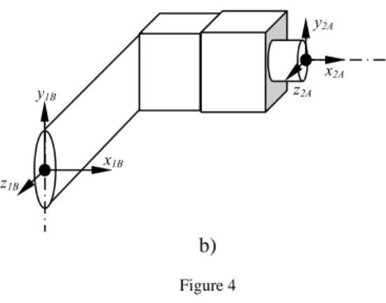
More precisely we intend to offer a picture of the modular robot construction from the previous discussed connection point of view. This graphical representation must contain all the possible connection and must bring out the chosen connection. Never the less the graphical construction is a graph which allow a future mathematical representation.
We have presented this graph in Figure 4a and for a better understanding in Figure 4b we have presented the picture of the chosen connection.
a)
y2B
z2B
x2A
x2B
F5B
y2A
z2A
F1A
x1A
y1A
z1A
y2B
z2B
x2B
F6B
z1A
x2A
y2A
z2A
x1A
y1A
F1A
BK
Bn
F1B
Aj-1,j
F2B
F3B
F4B
F5B
F6B
F1A
F2A
F3A
F4A
F5A
(βX; βY; βZ ) (Xk; Yk; Zk ) B1
Aj,i+1 Aj+1,j+2
b)
Figure 4 The connection graph
The graph (see Figure 4a) shows that we can choose one of the n available brackets and one of the thirty connections between this bracket and the follower joint. The goal is to find a mathematical form which contain implicitly all these possibilities.
The Homogenous Transformation between Joint j and Joint j+1
Using the graph from Figure 4a we propose the following homogenous transformation between joint j and joint j+1:
⎥⎥
⎥⎥
⎥
⎦
⎤
⎢⎢
⎢⎢
⎢
⎣
⎡
+ +
−
− +
+
− +
= +
+ +
+
+ +
+
+ +
+ +
Z i Y X i
X i
y k
i X i
Z X Y i
Z k
i y i
Z i
Z Y X k j j
q q
q Z
q q
q Y
q q
q A X
β β
β β
β
β β
β β β
β β
β β β
) cos(
) (
) sin(
) sin(
) sin(
) cos(
) (
) sin(
) sin(
) sin(
) cos(
) (
0 0
0 1
1 1
1
1 1
1
1 1
1 1
,
(12)
Some comments are necessary:
• The homogenous transformation Aj,j+1give us the position and the orientation of referential Ox2Ay2Az2A relative to the referential
B B By z
Ox1 1 1 (see also Figure 4b);
• The k index means that we have choused the link Bk in order to lie joint j to the joint j+1;
• βX,Y,Zare coefficients which define the direction of joint j+1 relative to the main referential system of the robot. More precisely
{
1,0,1}
, ,YZ∈ −
βX , βI =−1 if joint j+1 has the direction – I, βI =0 if joint j+1 has the not the direction – I orI, βI =1 if joint j+1 has the direction I. The mathematical expression of these coefficients can be obtained from the following equation:
x1B
y1B
z1B
y2A
x2A
z2A
[ ]
j[ ]
Tp
Bk FiA FiB T p
Z Y
X R 1 0 0
0 ,
∏
1=
+ ⋅
β = β
β (13)
• The position is defined by the coordinate Xk,Yk,Zkwhich are computed with equations (2), were we use jSβX,βY,βZ matrix from equation (3-8) according to the value of βX,Y,Z coefficients;
• qj+1is the rotation angle in joint j+1;
Using these transformations (12) we can compute the position, orientation of the robot end point:
∏
−= +
= 1
0 1 , m
j j j
E A
P (14)
The Algorithm
If we summaries the previous results we can propose the following algorithm for the kinematical description of the modular robot:
• choosing a configuration means to choose a succession of brackets which are connected in a desired way to the joint;
• choosing a particular bracket means to know his dimensions lFiBBk,x,y,z;
• a desired connection between the bracket and the joint allows us to know the rotation matrix j+1RFpBBk,FqA, which describes this connection (11);
• knowing this matrix we can compute βX,Y,Z coefficients (13);
• with these coefficients we can choose jSβX,βY,βZ matrix (3-8) and compute Xk,Yk,Zkdimensions (2);
• in the meantime these coefficients give us the possibility to compute the homogenous transformation between two successive joints (12);
• after we have defined our robot configuration we will obtain an equation which lies the joint rotation with position, orientation of the robot end (14);
• this equation can be used to solve kinematics problems (direct, indirect etc).
Conclusions
Present paper develops the research on modular robots. If in [1] we have made a bibliographical research, and we have presented our work strategy, in this paper we have started the kinematical analysis of the modular robots. This research focuses only on robots with rotation joints which are reciprocally perpendicularly or parallel. The generality of our study have been ensured by the general form of the link which lies two successive joint and the generality of the connection type between the link and the joint.
The main result that we have achieved is the algorithm which allows the mathematical construction of the homogenous transformation between the modular robots joint. This formalism gives us the possibility to solve the direct kinematics problem: to obtain the position and orientation of the modular robot end point when we impose desired trajectories in the robot joints.
We will continue this study by focusing in the inverse kinematics problem, in the working volume etc.
Acknowledgements
This research work is supported by the Romanian Ministry of Education and Research trough CNCSIS project 895/2007.
References
[1] Bi, M., Zhang, W., Modularity Technology in Manufacturing: Taxonomy and Issuses, International Journal of Advance Manufacturing and Technology, 381-390,2001
[2] Huang, C.-C., Kusiak, A. Modularity in Design of Products and Systems.
IEEE Transactions on Systems, Man and Cybernetics, Part-A: Systems and Humans, 28(1), 66-77, 1998
[3] Ulrich, T. K., Eppinger, S. D. Product Design and Development, 2nd edition, New York:McGraw-Hill, Inc. 2001
[4] Thyssen, J., Hansen, P. K., Impacts for Modularization. International Conference on Engineering Design (ICED) 01 Glasgow, 21-23 August 2001
[5] Stake, R., A Hierarchical Classification of the Reasons for Dividing Products into Modules: a Theoretical Analysis of Module Drivers, Licentiate thesis, Royal Institute of Technology, Stockholm, Sweden, 2000 [6] Siddique, Z., Rosen, D., Product Platform Design: a Graph Grammar
Approach, Proceeding of DETC’99: 1999 ASME Design Engineering Technical Conferences, Las Vegas, Nevada, DETC99/DTM-8762, 12-16 September 1999
[7] Dobrescu, G., Reich, Y., Design of a Gradual Modular Platform and Variants for a Layout Product Family. International Conference on Engineering Design (ICED) 01 Glasgow, 21-23 August 2001
[8] Jiao, J., Tseng, M., A Methodology of Developing Product Family Architecture for Mass Customization, Journal of Intelligent Manufacturing, 10, pp. 3-20, 2001
[9] Otto, K., Identyfing Product Family Architecture Modularity Using Function and Variety Heristics. PaperWork Center for Innovation on Product Development, Massachusetts Institute of Technology, Cambridge, MA, 02139, USA, 2001
[10] Jose, A., Tollenaere, M., Using Modules and Platforms for Product Family Development: Design and Organizational Implications. Fifth International Conference in Integrated Design and Manufacturing in Mechnaical Engineering (IDMME), University of Bath, Bath United Kingdom, 2004 [11] Hata, T., Kimura, F., Design of Product Modularity for Life Cycle
Management, Department of precition Engineering, University of Tokio, Hongo, pp. 7-3-1, 2001
[12] Chakrabarti, A., Sharing in Design—Categories, Importance, and Issues.
International Conference on Engineering Design (ICED) 01 Glasgow, 21- 23 August 2001
[13] Agard, B. (2002) Contribution a` une me´thodologie de conception de produits a` forte diversite´. Ph.D. Thesis, INPG, Grenoble France. 2002 [14] Venkat, A., Rahul, R., Module-based Multiple Product Design. IIE
Proceedings, IERC, Sustainable Design Lab Engineering Management Department, University of Missouri-Rolla Rolla, MO-65401, 2002
[15] Pedersen, K., Allen, V., Mistree, F., Numerical Taxonomy—a Systematic Approach to Identifyngpotential Product Platforms. International Conference on Engineering Design (ICED) 01 Glasgow, 21-23 August 2001
[16] Mikkola J., Modularization in New Product Development: Implications for product Architectures, Supply Chain Management, and Industry Structures.
Ph.D. Thesis, School of Technologies of Managing, Copenhagen Business School, Denmark, 2003
[17] Dahmus, J. B., Gonzalez-Zugasti, J. P., Otto, K. N., Modular Product Architecture. Design Studies, 22(5), 409-424, 2001
[18] Chidambaram, B., Agogino, A., Catalog-based Customization, Proceeding of DETC’99: 1999 ASME Design Engineering Technical Conferences, Las Vegas, Nevada, DETC99/DAC-8675, 12-16 September 1999
[19] Sand, J. C. House of Modular Enhancement (Home): a Design Tool for Product Modularization, University of Saskachetwan, Master thesis, 1999
[20] Jose, A., Tollenaere M., Modular and Platform Methods for Product Family Design: Literature Analysis, Journal of Intelligent Manufacturing 16, 371- 390, 2005
[21] Xu, H., Brussel, H., A Behaviour-based Arhitecture with Attention Control, Journal of Inteligent Manufacturing 1998,9,97-106
[22] Young K, Hybrid Control for Authonomus Mobile robot Navigation Using Neuronal Network-based Behaviour Modules and Environement Clasification, 2003 Authonomus Robots 15, 193-206, Kluwer Academic Publishers, 2003
[23] Mehmet O., Adaptive Fuzzy Sliding Mode Control for a Class of Bipartite Modular Robotic Systems Journal of Electrical and Electronice Engineering, Vol. 3 645-661, 2003
[24] R. Fitch, Z. Butler, Z., 3D Rectilinear Motion Planning with Minimum Bend Paths. In Proc. of the Int’l Conf. on Intelligent Robots and Systems, 2001
[25] Murata, S., Hardware Design of Modular Robotic System, IEEE-RSJ Int.
Conf. on Intelligent Robots and System 2000
[26] Yoshida, E Miniaturization of Self–Reconfigurable Robotic System using Shape Memory Alloy Actuators, J. of Robotics and Mechatronics, Vol. 12 No. 2, 96-102, 2002
[27] Fromherz, M., Hogg, T., Shang, Y., Jackson, W., Modular Robot Control and Continuous Constraint Satisfaction IJCAI-01 Workshop on Modelling and Solving Problems with Constrains, 2001
[28] www.lego.com
[29] Chen, I., Yang, G., Automatic Generation of Dynamics for Modular Robots with Hybrid Geometry. In IEEE ICRA, pp. 2288-2293, 1999
[30] Farritor, S., On Modular Design and Planning for Field Robotic Systems, Ph.D. Thesis, Massachusetts Institute of Technology, May 1998
[31] R. Sinha, V. C. Liang, Modeling and Simulation Methods for Design of Engineering Systems, Journal of Computing and Information Science in Engineering. Vol. 1, pp. 84-91, 2001
[32] Farritor, S., On Modular Design of Field Robotic System, Autonomous Robots 10, 57-65, 2001 Kluwer Academic Publishers. Manufactured in The Netherlands 2001
[33] Chen, I., Burdick, J, Determining Task Optimal Robot Assembly Configurations. In IEEE Intl. Conf. on Robotics and Automation, pp. 132- 137; 2002
[34] Soshi, I., Paredis, J., Khosla, K., Interactive Multi-Modal Robot Programming, IEEE International Conference on Robotics and Automation Washington DC 2002
[35] Kang, S-H., Pryor, M., Tesar, D., Kinematic Model and Metrology System for Modular Robot Calibration, 2005
[36] S. Shin, D. Tesar, “Analytical Integration of Tolerances in Designing Precision Interfaces for Modular Robotics,” Ph.D. Dissertation, The University of Texas at Austin, 2004
[37] Cameron, T., Legault, J., Cox, D., Tesar, D., Configuration Management for Modular Flexible Small Automation System: A Case Study; 2004 [38] Cox, D., Legault, J., Turner, C., Tesar, D., Automated Plutonium
Processing Work Cell Technology, UAmerican Nuclear Society Proceedings of the 7UPUthUPU Topical meeting on Robotics and Remote SystemsU, April 1999
[39] Legault, J., Tesar, D. Reducing Complexity of Automated Systems Through Configuration Management, Masters Thesis, The University of Texas at Austin, 2000
[40] Slotine, J. J., Aplied Nonlinear Control Prentince Hall 2000 [41] Dorf, R., Bishop, R., Modern Control Systems Prentince Hall 2004
[42] Hung Vu, Dynamic Systems: Modeling and Analysis, Ed. McGraw Hill, 1997
[43] Pozna, C., Modular Robots Design Concepts and Research Directions. In Proceedings of 5th International Symphosium on Inteligent Systems and Informatics. IEEE Catalog Number 07EX1865C, ISBN 1-4244-1443-1 [44] Gogu, G., Representation du mouvement des corps solides, Hermes, Paris
1996