IAUNCH-ON-TIME ANALYSIS FOR SPACE MISSIONS C. E . Kohlhase1
Jet Propulsion Laboratory, California Institute of Technology ABSTRACT
Lunar and interplanetary trajectories are dependent on time of launch as a result of the relative motion between the launch site and destination* It is therefore essential to understand the geometric aspects of this dependency in order to establish the guidance criteria necessary to correctly direct the vehicle in the presence of firing-time delays that may occur at the launching complex.
The launch-on-time problem is analyzed by realizing that the primary defining quantities for deep-space missions are the pseudo-asymptote and energy of the departure conic (coast tra- jectory). The goal of the injection guidance system is there- fore to steer the vehicle so that at injection (when final burning is terminated) the coast trajectory will exhibit the desired energy and pseudo-asymptotic direction. Practical tra- jectories for deep-space missions will generally use parking orbits in order to relieve geometric constraints. The launch- on-time problem can be handled by changing the firing azimuth and parking-orbit coasting arc. This eliminates the necessity for any dramatic vehicle maneuvers that would result in per- formance degradation. It is this consideration that severely limits the firing window (allowable launch delay) for direct- ascent missions, as the direct-ascent vehicle must fly a steeper flight path in order to compensate for launch-time delay.
INTRODUCTION
Trajectory dependency on time of launch is present when- ever there is relative motion between the launch site and destination. This situation does not arise for ballistic-
Presented at ARS Guidance, Control, and Navigation Confer- ence, Stanford University, Stanford, Calif., Aug. 7-9, 1961;
this paper gives results of one phase of research carried out at the Jet Propulsion Laboratory, California Institute of Technology, under Contract NASw-6, sponsored by NASA.
"^Research Engineer, Systems Analysis Section.
missile or Earth-satellite trajectories, but for lunar and planetary missions, the geometry between the launch site and
destination continuously change6with time, due, primarily, to Earth's rotation about its axis and, secondarily, to the motion of the target body relative to Earth. It is therefore important to understand trajectory behavior with launch time in order to establish the guidance criteria necessary to prop- erly direct the vehicle in the presence of unforeseen firing- time delays that may occur at the launching complex during an attempt to launch at some preselected standard firing time.
G U I D A N C E E L E M E N T S
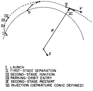
It has been shownjay other authors (1,2)2 that the out- ward radial direction S (also termed the pseudo-asymptote) and the departure conic energy3 C3 are the primary defining quan- tities for lunar and planetary trajectories. In view of this important dependency, the goal of the injection guidance sys- tem will be to steer the vehicle so that the prescribed asymp- tote and energy will be achieved at injection. As can^be seen from Fig. 1 , for planetary missions, the unit vector S lies along the asymptote to the standard departure hyperbola and, for lunar missions, S lies along the position vector of the
"massless" Moon at the predicted time of lunar encounter.^It can usually be assumed that over a period of a few hours S and C3 remain essentially constant for planetary missions, and S moves with the Moon for lunar missions.
In order to satisfy the asymptote-energy requirements, the guidance system could employ:
1) Yaw steering to force the vehicle plane of motion to contain S;
2) pitch steering to properly orient the departure conic trajectory within the vehicle plane of motion;
3) termination of final-stage burning upon reaching the nominal** value of C3.
^Numbers in parentheses indicate References at end of paper.
3The departure conic energy is twice the total energy per unit mass.
^For lunar trajectories, this is essentially equivalent to maintaining the nominal flight time, so that the vehicle will encounter the Moon late by the amount of the launch-time
delay.
Figs. 2 and 3 illustrate the in-plane points of interest for parking-orbit and direct-ascent powered-flight trajectory pro- files for a two-stage vehicle with second-stage restart capa- bility. Point Β represents the position of the launch site after Earth has rotated during the launch-time-delay interval.
Yaw steering may be accomplished by nulling a signal propor- tional to S χ V · S. Because of aerodynamic (and other) con- straints, the first portion of the booster stage is usually flown "open loop"; that is, in a preprogrammed manner without guidance steering. When truly guided flight begins, the vehicle might well be off course, requiring a significant maneuver to return to the proper plane of motion. If the inte- gral of thrust acceleration in the plane of motion is to be maintained at some fixed value, then it is very important that the vehicle not be required to execute any large yaw maneuvers.
Launch-time delays can be compensated more conveniently and efficiently with parking-orbit trajectories than with direct-ascent trajectories. In the former case, it is a simple matter to vary the parking-orbit interval in order to maintain the proper in-plane orientation of the departure conic, but in the latter case, injection must occur at larger values of true anomaly and can only be accomplished by flying a steeper flight path with its associated reduction in vehicle perform- ance ( 3 ) ·
FIRING AZIMUTH FROM NONROTATING SPHERICAL EARTH
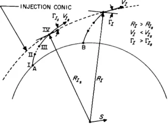
Although the guidance system could, in theory, achieve the desired injection conic regardless of the initial direc- tion in which the vehicle is launched, from a practical stand- point it is mandatory that the vehicle not be required to execute any dramatic maneuvers. For this reason, it makes sense to determine an initial firing azimuth that corresponds to the desired vehicle plane of motion. An approximate value of the desired launch azimuth can be obtained analytically by considering the simple model of a nonrotating spherical Earth (fixed at the instant of lift-off) shown in Fig. U.
Normally, the vehicle roll axis is erected along the plumb line or geodetic vertical at the launching complex, and the firing azimuth is then the angle measured clockwise from north to the projection of the vehicle thrust vector (as soon as the vehicle is pitched over from the vertical) onto the local geodetic horizontal plane. For the simple spherical- Earth model of Fig. k the geodetic and geocentric verticals are coincident.
The unit vector rj,, which points from the center of Earth through the launching site, is given by
? L β i c o s V L c o s ® L • "j cos ^ L s i n ®L • k sin* L [l]
where ψ χ, and ® L a1*6 ^ e geocentric latitude and right ascen- sion of the launch site, and i, j, k are unit vectors defined by a space fixed, equatorial, rectangular coordinate system with the x-axis towards the vernal equinox ( Τ ) . The unit vec- tor a, pointing down the firing azimuth, is given by
a = |[k χ rL] sin aL - [(k χ rL) x T L ] COS aLj > sec ψ L [2]
The unit normal vector Ν to the plane of motion is given by
? L χ a and, for a nonrotating, spherical Earth, the correct firing azimuth may be obtained by solving the equation Ν · S « 0 for σι
σι - t a n "1
Sx s i n ®L - Sy c o s ©L -, ( Sx c o s ( H )L + Sy s i n Q pL) sin <//L- Sz cos ψ^ Μ
Because of Earth rotation, the right ascension of the launch site ® L is related to the launch-time delay Δ t^ by
® L - ® L +" eA tL S
where ® is the launch-site right ascension at the standard firing time, and ωβ is the average angular velocity of the Earth.
A situation is imagined that is defined by assuming
® Ls " °f Ψ ΐ β 2^ · 3 ° (Atlantic Missile Range)^ and S » -i cos ψ£ • k sin ψ2, where ψ 5 is the declination of S. This situa- tion is described by Fig. which illustrates firing azimuth behavior with launch time for several values of ψ5 . Although Eq. 3 admits two possible firing azimuths for any given firing time, only the easterly values ( 0< σ^ < ΐ 8 0 ° ) have been shown in Fig# 5. The curves exhibit two characteristic patterns, with the critical boundary occurring at Β I + L I * ^ I I F
noted that for)*// s| < |Ψ^|, it is possible to fire at all
azimuths (within range-safety limits), but for | ψ31 > a symmetric band of firing azimuths about due east is eliminated (3· U)# Launch-on-time considerations generally favor launch- ing when the rate of change of firing azimuth with launch time is a minimum, if possible, as the associated firing windows are usually longer and the tracking geometry varies at the slowest possible rate. Accordingly, it is least desirable to select a nominal firing time for which the daj/dt^ is very
large. Although Fig. $ illustrates firing-azimuth behavior with launch time for what appears (from the symmetry involved) to be a very special situation, it is actually representative of any real situation (for ψγ = 28.3°) by a simple translation of the launch-time axis. This is apparent when it is realized that any S vector may be expressed in the form assumed for Fig.
5 by performing a rotation of the equatorial coordinate axes in order to null Sy.
Fig. $ is very useful in determining the expected firing- window5 width, given the limiting azimuths for adequate
tracking coverage. For example, good tracking facilities exist for trajectories launched to the southeast from the Atlantic Missile Range from about 95 to 110°. For most lunar and planetary missions, this would correspond to a firing window of between one and three hours during each day.
ROTATING SPHERICAL EARTH
The curves of Fig. $ have assumed that, at the instant of launch, Earth is nonrotating. The actual firing azimuth from a rotating Earth will, in general, lie slightly away from east of the azimuth given by Eq. 3· This deviation is essentially due to the initial crossrange-rate component present at launch. Fig. 6 displays an inertial, rectangular, launch-site coordinate system, defined at the instant of^launch. IT is perpendicular to the spherical Earth model, XL points along the downrange or azimuthal heading, and Z^ » Χ^ χ Ϋ^.
•
If expressions are developed for Z^ and Zj^, then the amount by which Ν has been rotated may be determined. If drag is neglected and the assumption is made that vehicle thrust is maintained parallel to the plane, then
where Κ may be thought of as a time-averaged value of over thejpowered flight from launch to the point where the rotation of Ν is to be determined. Integration of Eq. U leads to
ZL - Z ^ cos (K2t)
[5]
^The firing window refers to that period of time during which the vehicle may be launched without violating any of
several constraints.
ZL = K"2 Zj^ sin (K*t)
[6j
where 2]^ is equal to the product of Earth's eastward surface velocity at the launch site and the cosine of the firing azimuth
It is imagined that the vehicle is launched from a nonrotating Earth, flown to some point, and then an instanta- neous Z L is applied. This would have^the effect of rotating the plane of motion negatively about R by an amount Z L
(V cos Γ )"•*·· The application of an instantaneous Z L would be equivalent to a rotation of Z L ( R COS Γ about a line through the center of Earth and parallel to v\ It would ^ , therefore seem appropriate to define the rotation vector ρ
Ρ = c ^1 ( ZL V - Z L R ) [7]
where the angularjroomentum s R V cos Γ. Eq. 7 is a valid approximation as ρ is a small rotation. An inertial observer located far above the launch site and looking in the -Ϋ^
direction would observe the trajectory curving to the right (for a southeast firing) as the vehicle accelerates downrange, after being launched with an eastward inertial velocity
imparted by Earth rotation. In order that the actual plane of motion defined at injection contain the desired S, it is necessary that
(N
ρ
χ Ν) · S » 0[8]
Solution of Eq. 8 for yields the same expression as Eq. 3 with Sx, Sy, Sz replaced by S£, S£, S£, where
Si • Sx + Sy f>z - Sz Py
sy - sy + sz Px - sx Pz
H
" Sz + sx Py * sy PxFig. 7 illustrates the effect of Earth rotation (initial cross- range rate) upon firing azimuth for a typical firing situation.
An approximate method for determining ρ is given in the Appendix.
8
As might have been expected, there is no rotation of the plane of motion for trajectories fired due east (or west) from a spherical Earth and maximum rotation for those launched due south (or north). The quantity Δ σ ^ represents the additional amount by which the firing axirauth must be rotated away from east in order to compensate for initial crossrange rate and attain the desired plane of motion at injection. Experience has shown that the value of computed for a rotating, spherical Earth is very close (within 0·$°) to the actual value for a rotating, oblate Earth. There is no need to
conduct a detailed analysis of the effects of oblateness in order to obtain an exact value for σ^9 as guidance system yaw steering will achieve the desired plane of motion with
negligible loss in vehicle performance.
It should be noted that changing launch azimuth away from due east causes a performance loss because of the diminished component of "Earth's rate" in the plane of motion. The launch site is moving with speed * ω β κΙ , c o s^ L r elat i v e to the center of Earth, and this contributes to meeting the inertial energy requirements at first-stage burnout. The component of in the plane of motion is
sin s ^e^L c os ^ L s*n °"L
which implies that additional thrusting is required if is changed away from 90°.
COAST-TIME CORRECTION
The second part of the launch-on-time problem, from the guidance point of view, is controlling the orientation of the departure conic in the plane of motion. This can be handled rather simply for trajectories with parking orbits by assuming that the last burn profile will stay essentially fixed (the departure conic will be standard) and by igniting the last stage at the proper place in inertial space by varying the parking-orbit interval (see Fig. 2). JThis^can be done by initiating last burn when the signal Rg · Ss - R * ^ goes to zero in the guidance computer, thereby causing the in-plane angle between the beginning of the last burn and 3? to have the standard value. The coast-time variation A tc is given by
A tc - RCVC
where Rc and are the parking-orbit radius and velocity. If t*t > 0 for r and rT, the coast-time correction is given by
cos 1 (S, cos (rT
0]
- Δ tc as defined by Eq. 9· For lunar trajectories and launch- time delays not in excess of a few hours, S varies approxi- mately as
^ R ms + A tL Vra
s
[10]
Κ +A tLVr a s|
where ^ ms and ^ms are the geocentric position and velocity of the "massless" Moon at the standard time of expected encounter.
Eq. 10 has assumed that since the standard injection energy is maintained, the flight time from injection to lunar encounter does not change appreciably for nominal launch-time delays.
Eq. 10 also neglects A tc, which is small ( A tc^ - 0 . 0 £ A t . ) in comparison with Δ t ^ . For planetary missions, S ^ Ss, trie asymptote to the standard departing geofocal hyperbola.
Strictly speaking, the heliocentric geometry has undergone a small change after the passage of a launch-time delay, but during the.short time associated with a^typical firing window, negligible' error is made by assuming S s Ss. In actual practice, however, several trajectories from launch to planet encounter would be run (on an accurate digital computer trajectory program) at launch-time intervals every fifteen minutes or so after the nominal firing time, over the firing window. Then a simple § ( Δ ^ ) fit would be obtained from the trajectory data and used in the asymptote-guidance equations.
Fig. 8 illustrates coast-time variation (based upon 100-n mi circular parking orbit) with launch time for the symmetric situation described by Fig. The discontinuity at Δ ^ = 12 results from considering only the easterly firing azimuths ( 0^ o ^ < l 8 0 ° ) . Fig. 8 further assumes that whenever the downrange angle from Γ τ to § is less than l80°, then the vehicle must coast around Earth before departure. The value of this minimum downrange angle is dependent upon the type of vehicle and the particular mission (l). For many of the current vehicles and anticipated missions, this angle may vary from about l£0 to 200°, and 180° was merely chosen as a typical value. For all possible parking-orbit trajectories,
0 < I a tc/dtjj< cjçRçVç-1. Typically, d tç/ d tL^ - 0 . 0 5 about the nominal firing time for many of the envisaged space missions that employ the parking-orbit technique.
^That is, negligible in comparison with target dispersions that result from component error sources in the injection
guidance system.
Attaining the proper in-plane orientation of the departure conic for direct-ascent trajectories cannot be achieved in the same manner as for parking-orbit missions.
Since there is no coast interval to vary, the equivalent com- pensation for a direct-ascent trajectory must be accomplished by varying the true anomaly at injection; that is, by injecting at a different point on the coast trajectory (see Fig. 3)·
Since the optimum injection point (near perigee) usually corresponds to a launching time close to the nominal, it follows that the last stage must be pitched up for a late launching. This causes a loss in vehicle performance because of the less efficient flight path. It is for this reason that the firing window is shorter for direct-ascent than for
parking-orbit trajectories.
CONCLUSIONS
It has been shown that launch-time variations may be compensated very simply by changing the firing azimuth and coasting arc for parking-orbit trajectories. The allowable firing-time delay for direct-ascent missions is severely limited, however, due to the necessity of flying a steeper and less efficient flight path.
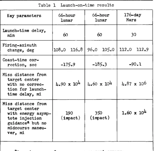
In order to verify the efficacy of energy-asymptote guidance, several standard parking-orbit trajectories were rerun (with launch-time variations) on the IBM 70U digital computer. The results of three typical missions have been summarized in Table 10
APPENDIX
The amount of rotation of the powered-flight plane of motion depends upon the firing azimuth. Neglecting oblateness, there would be no rotation for trajectories fired due east or west and maximum rotation for those launched due north or
south. Therefore, in order to compute σ^, ρ must be known, but in order to determine ρ, στ must be known. This situation may be handled without difficulty by first computing the firing azimuth from Eq. 3· Use of this equation is consistent with the assumption that the vehicle is flown to some point
(Earth-fixed at instant of lift-off) and that instantaneous Z L and Zj, are then applied to determine the rotation of the
£owered-flight plane of motion. If it is desired to determine ρ at injection
Pi "
"αϊ*
(ZL! *i - \V
where C^j is simply the standard injection angular momentum, and Ri and Vj may be determined approximately by utilizing the norrotating spherical Earth model. For parking-orbit trajec- tories, it can be assumed that injection occurs at the standard in-plane angle from S. Fig. 9 illustrates the in-plane quanti- ties.
It can be seen that
Kl "RIS (S cos α • Τ sin α ) [AI]
Vj = Vj (S sin β - Τ cos β) [A2]
where
α» cos-^Rlg · jj* ) , β - α + ΓΙ β,
and
î ( rL' S ) S - ; L
[A3]
If a · S > 0, it will be necessary to use -T as defined by Eq. A3. Finally, it is necessary to determine Ζ τ and ZLj«
In Eqs.
5
and6
Zj^ 3 UQR'I, COSI/ZL cos a L £aUJ where R^ is the radius of Earth at the launch site and may
be computed from Eq. 3· The time from launch to injection tj is given by
where Δ tc is given by Eq. 9.
NOMENCLATURE
a « unit vector along azimuthal heading at launch Cj « angular momentum defined by RV cos Γ
C«3 » twice total energy per unit mass and equal to V2 - 2/ x R "1
Κ « time-averaged value of /xR"3 over powered flight
^ from launch to point where 'p is desired
Ν » unit vector normal to vehicle (launched from non- rotating Earth) plane of motion
R β position vector of vehicle Rc * circular parking-orbit radius
Rm s s position vector of "massless" Moon at time of expected lunar encounter
r^ « unit vector pointing from center of Earth through
^ launching site
S s unit vector along asymptote to departure hyperbola, for interplanetary missions; lies along lunar posi- tion vector at time of predicted encounter with
"massless" Moon, for lunar missions t » time measured from lift-off
Τ - unit vector normal to S in plane of motion
^ V » inertial velocity of vehicle
Vra « inertial velocity (relative to Earth's center) of
^ A f Moon at standard time of predicted lunar encounter Χ,Υ,Ζ » space fixed, equatorial rectangular coordinate sys- tem with X-axis toward vernal equinox; prescribes
^ ^ ^ unit vectors Î , J, k
^L'^L'^L * *n e rk i a l launch site coordinate system, defined at
# instant of launch
Z]>ZL * vehicle crossrange and crossrange rate for simpli- fied mathematical model of Fig. 6
α β nominal downrange angle from injection to pseudo- asymptote, for parking-orbit missions
ß 88 α •
Γι
Γ s angle from local horizontal plane to inertial velocity vector
A tc « parking-orbit coast-time correction
Δΐ-τ « launch-time variation (positive for late launch) (φ m right ascension
μ β gravitational constant for Earth ( G Me)
jo a rotation vector of powered-flight plane of motion σι * firing azimuth measured clockwise from north
ψ * geocentric latitude or declination we « average angular velocity of Earth SUBSCRIPTS
c * circular parking-orbit conditions I « injection values
L = launch site m » lunar quantities
s s values associated with the standard, no launch time variation trajectory
S « pseudo-asymptote
x,y,ζ β components in Χ, Υ, Ζ coordinate system ο β initial value of given parameter
REFERENCES
1 Clarke, V. C , "Design of lunar and interplanetary ascent trajectories,11 Jet Propulsion Lab. Tech. Rept. 32-30, Calif. Instit. Technology, Pasadena, Calif., July 26, I 9 6 0 .
2 Sauer, C G., Jr., "Interplanetary injection guidance,"
Jet Propulsion Lab. Tech. Rept. 3U-88, Calif. Instit.
Technology, Pasadena, Calif., Oct. 25, I 9 6 0 .
3 Seifert, Howard S . , Space Technology (John Wiley and Sons, Inc., New York, 1 9 5 9 ) , Chap. 8, pp. 8 8 - 9 0 .
U "Lunar probe flight; introduction to flight geometry and accuracy problems," ABMA DA Tech. Note No. 58-58, Redstone Arsenal, Ala., Aug. 22, 1958, pp. 1 7 - 2 2 .
Table 1 Launch-on-time results Key parameters 66-hour
lunar
66-hour lunar
176-day Mars Launch-time delay,
min 60 60 30
Firing-azimuth
change, deg 108.0 116.8 96.0 105.0 112.0 1 1 2 . 9 Coast-time cor-
rection, sec -175.9 -185-3 -90.1 Miss distance from
target center with no correc- tion for launch- time delay, mi
U.90 χ 101* U.60 χ ΙΟ1* U.87 χ 106
Miss distance from target center with energy asymp- tote injection guidancea but no midcourse maneu- ver, mi
190 (impact)
350 (impact)
1.60 χ 10^
aAssuming no performance or component errors
LUNAR M I S S I O N S
Fig. 1 Psuedo-asymptotic direction
I LAUNCH
U F I R S T - S T A G E SEPARATION ΉΓ S E C O N D - S T A G E IGNITION I Z PARKING-ORBIT ENTRY 3Γ S E C O N D - S T A G E RESTART
ΊΠ. INJECTION (DEPARTURE CONIC D E F I N E D )
Fig. 2 Parking-orbit trajectory profile
ΠΓ S E C O N D - S T A G E IGNITION TSL I N J E C T I O N
Fig. 3 Direct-ascent trajectory profile
Fig. k Coordinate system and associated quantities