IOP Conference Series: Materials Science and Engineering
PAPER • OPEN ACCESS
Effects of different backing gases on 2404 duplex stainless steel welds
To cite this article: B Varbai et al 2018 IOP Conf. Ser.: Mater. Sci. Eng. 426 012051
View the article online for updates and enhancements.
This content was downloaded from IP address 152.66.32.32 on 18/10/2018 at 14:19
1234567890‘’“”
11th Hungarian Conference on Materials Science IOP Publishing
IOP Conf. Series: Materials Science and Engineering 426 (2018) 012051 doi:10.1088/1757-899X/426/1/012051
Effects of different backing gases on 2404 duplex stainless steel welds
B Varbai1, *, I Mészáros1 and K Májlinger1
1 Budapest University of Technology and Economics, Department of Materials Science and Engineering, Budapest, Hungary
E-mail: varbai@eik.bme.hu
Abstract. In our research butt welds were made on newly developed LDX 2404 lean duplex stainless steel grade with gas metal arc welding. For root protection three different backing gases were used: pure argon, 95 vol% nitrogen + 5 vol% hydrogen and pure nitrogen. In case of pure nitrogen backing the effect of different gas flow rates was also investigated. Based on our research, the nitrogen content in the backing gas resulted in increasing austenite content. The increasing nitrogen content in backing gas and the increasing austenite content resulted in increasing pitting corrosion resistance. The flow rate of the backing gas also has significant effect on the evolving microstructure and pitting corrosion resistance.
1. Introduction
High strength and novel corrosion resistant steels gain more attention in chemical, offshore and pulp industries [1–9]. Among stainless steels, duplex stainless steels (DSS) have excellent corrosion resistance due to the austenitic – ferritic microstructure, which is a result of austenite and ferrite forming alloying elements and heat treatment [10–15]. Because of the recent fluctuations in nickel and molybdenum prices of metal stock market, steel industries have developed new types of stainless steels with lower nickel and higher manganese and nitrogen alloying contents [16–18]. These special types of new DSS called “lean” duplex, indicating their lower nickel content [19–22]. Recently, lean DSS gaining more attention due to their high mechanical strength and corrosion resistance and lower price compared to the conventional DSS grades, such as EN 1.4462 (UNS S31803).
The welding of DSS is often challenging, because of their high alloying content and the metastable microstructure, which also depends on the weld thermal cycles [23–27]. For compensation of nitrogen loss during welding and to ensure optimal, 1:1 phase balance in duplex microstructure, nitrogen shielding gas is often used during arc welding [28–31]. However, nitrogen does not always solve the weldability issues of high nitrogen stainless steel as detrimental phases such as chromium-nitrides [32, 33] can precipitate and also porosity formation [34, 35] can occur.
The effects of nitrogen used as backing gas during welding is not well published yet in the professional open literature. Westin et al. [36–38] published their results on nitrogen, argon + nitrogen and nitrogen + hydrogen backing gas effects on the corrosion resistance and microstructure of conventional, lean and super DSS grades. According to their research nitrogen has an effect on the microstructure, even when used as a backing gas. As a result, in case of nitrogen gas root protection higher austenite content could be measured on weld root and the corrosion resistance improves.
In our research, butt welds were made with gas metal arc welding on a newly developed LDX 2404 lean duplex grade (UNS S82441, EN 1.4662). For root protection three different backing gases:
2
1234567890‘’“”
11th Hungarian Conference on Materials Science IOP Publishing
IOP Conf. Series: Materials Science and Engineering 426 (2018) 012051 doi:10.1088/1757-899X/426/1/012051
100 vol% argon, 95 vol% nitrogen + 5 vol% hydrogen and 100 vol% nitrogen was used. The effect of different backing gas flow rates were also investigated and found to have an effect on the evolving microstructure.
2. Materials and methods 2.1. Base and filler materials
The used base material was lean duplex LDX 2404 grade with lower nickel and higher nitrogen and manganese alloying content (Table 1.). The higher N and Mn alloying ensures the high yield strength (Rp0.2 = 640 MPa in case of cold rolled sheets) of LDX 2404 grade. Also, because of the high nitrogen and molybdenum (Mo = 1.6 wt%) content, the LDX 2404 grade offers good resistance to localized and uniform corrosion. For welding 3 mm thick sheets were used.
The used filler wire for MAG (metal active gas) welding was general duplex wire ISO 14343-B- SS2209 grade with 1.2 mm diameter. The filler wire contains higher nickel content (Ni = 8.5 wt%) in order to ensure adequate austenite formation during welding.
Table 1. Main alloying contents of the used LDX 2404 base material (BM) and the SS2209 welding wire (W). CrE and NiE values are calculated according to the DeLong diagram Material
designation
Measured alloying content in wt%
C Si Mn Cr Ni Mo N Fe CrE NiE
LDX 2404 (BM) 0.02 0.7 3.0 24.0 3.6 1.6 0.27 bal. 26.75 13.80 SS 2209 (W) 0.02 0.5 1.6 22.8 8.5 3.1 0.17 bal. 26.65 15.00 2.2. Welding parameters
Robotized MAG welding machine was used to ensure constant welding parameters. The butt welds were made in flat position, without chamfering and keeping a constant 1 mm root gap. The applied heat input was 0.26 kJ ∙ mm-1, calculated with k = 0.8 thermal efficiency factor, according to EN 1011 standard.
For all welds on the face side the same shielding gas was used, 98 vol% Ar + 2 vol% O2 – which mixture is recommended for DSS MAG welding – with 15 l ∙ min-1 flow rate. For root protection three different backing gases with 9 l ∙ min-1 flow rate were used: pure Ar, 95 vol% N2 + 5 vol% H2 (forming gas) and pure N2 (with 4 l ∙ min-1 flow rate too). One weld was done without root protection, exposed to ambient air. For the listed backing gas mixtures for specimen designation only; Ar, 95 N2 + 5 H2 and N2
were used. After welding the samples were not pickled and re-passivated unlike industrial practices.
2.3. Microstructure investigations
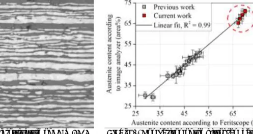
Standard metallographic specimens were done from all welded joint cross-sections. The color etching was done, using Beraha mixture [39]: 85 ml H2O + 15 ml HCl + 1 g K2S2O5, using double etching method. On all metallographic images the austenite phases will appear light and the ferrite phases appear dark e.g. as seen on Figure 1.
The microstructure images were taken using Olympus PMG 3 type microscope. For taking the macro images of the welds face and root before and after corrosion tests Olympus SZX16 type stereomicroscope was used.
2.4. Austenite content measurement
For austenite content measurement two different methods were used. (I) on the as welded samples Feritscope measurements were done, using Fischer FMP30 instrument, which measures the volume of the ferromagnetic phases (ferrite in our case). And (II) on the images taken by microscope (from the etched cross-section of the welds) image analyzer software can be used to determine the austenite – ferrite phase ratio. The steps of the image analyzing are the following. The original image is loaded to an image analyzer software and the grayscale histogram is taken up on the 0 to 255 range (8 bit). The histogram has two peaks; one at a darker gray level and one at a lighter gray level. The difference between the two gray level peaks is equivalent to the level of contrast of the image. In order to count the
1234567890‘’“”
11th Hungarian Conference on Materials Science IOP Publishing
IOP Conf. Series: Materials Science and Engineering 426 (2018) 012051 doi:10.1088/1757-899X/426/1/012051
darker and lighter number of pixels (which is in correlation to the austenite – ferrite ratio) the original image should be converted into a black and white image. To do this, the difference between the two peaks can be used as a threshold to determine if the pixel is to be converted to black or white. Whit this method the austenite-to-ferrite ratio can be calculated after correlated to the black and white pixel ratio.
The comparison of the two methods can be seen on Figure 2., where a 45° straight line is fitted on the points measured with both methods. A linear fit with R2 = 0.99 is determined, meaning both of the two methods can be used for austenite content measurement with the same results. In this paper in the further diagrams Fischer type Feritscope was used to determine the austenite-to-ferrite ratio in the welds.
Figure 1. Etched microstructure of LDX 2404 base material (white is the austenite
and dark is the ferrite phase)
Figure 2. Comparison of the histogram based image analyzer and the electromagnetic based Feritscope austenite content measurements 2.5. Corrosion rate measurements
For the measurement of corrosion resistance ferric chloride pitting test was performed, according to code: ASTM G48 – Method A. For the test equal sections from all welded sheets were cut out using constant cooling, with the dimensions of 25 × 25 × 3 mm. The samples were immersed into 6 % FeCl3
– H2O solution for 72 hours at 50 ± 1 °C temperature. The weight of the samples was measured before and after the test with Denver Instrument SI-8007 instrument with 0.1 mg accuracy. Before and after the corrosion test ultrasonic cleaning was done in acetone in order to remove corrosion products and the samples were dried before the weight measurements.
3. Results and discussion
3.1. Macro- and microstructure of welds
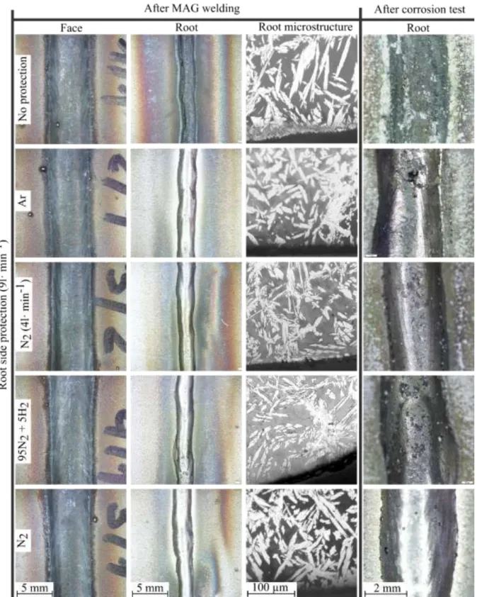
With visual inspection no difference can be seen on the face side of the welds (Figure 3.). When no root side protection was applied, the root side oxidized and porous structure was visible. On the metallographic images the average measured oxidized layer depth is 20 µm.
Between the Ar and N2 root protection no significant differences are visible on macroscale in the as- welded condition. When backing gas was not used for root protection an average of 100 × 100 µm oxidized areas are visible on the surface. These areas were later initiation sites for localized corrosion.
After the 72 hours corrosion test no differences were seen on face side of the welds as a function of the used backing gases, however significant differences were visible on the root side. When no root protection was applied the root side of the weld completely corroded, resulting the disappearance of the weld root after the corrosion test. In case of Ar root shielding localized corroded areas are visible with the average sizes of 500 × 500 µm. Also significant difference can be seen between the two samples welded with N2 root protection, but different flow rates. In case of lower backing nitrogen gas flow rate (4 l ∙ min-1) shallow localized corroded areas are seen with average 100 × 100 µm size. With the higher
4
1234567890‘’“”
11th Hungarian Conference on Materials Science IOP Publishing
IOP Conf. Series: Materials Science and Engineering 426 (2018) 012051 doi:10.1088/1757-899X/426/1/012051
(9 l ∙ min-1) nitrogen backing flow rate much smaller (average 20 µm) localized corroded areas were seen.
As a summary it can be stated the higher flow rate pure nitrogen and argon root protection showed the best surface in terms of corrosion resistance.
Figure 3. Macro- and microstructure of welds before and after corrosion test
1234567890‘’“”
11th Hungarian Conference on Materials Science IOP Publishing
IOP Conf. Series: Materials Science and Engineering 426 (2018) 012051 doi:10.1088/1757-899X/426/1/012051
3.2. Austenite ratio at the weld root
The average austenite ratio of the LDX 2404 base material is 59 vol% (Figure 4.). The austenite content of the weld face side did not change (65 ± 3 vol%) as a function of different backing gases used.
However, on the root side of the welds different austenite ratios were measured.
Generally, the austenite content of the weld root increased with the increasing nitrogen content in the backing gas (Figure 4.). In case no root protection was used (the root side was exposed to air) the highest austenite content was measured, which is a measurement method error. The reason for this is the oxidation, which occurred on the root side and resulted in porous structure. The Feritscope measurement on this porous microstructure resulted in higher non-magnetic volume, which appears in lower ferrite content during the measurement. On the metallographic specimen of this weld, image analysis was done, which gave the result of 55.9 ±1.5 area% austenite content. It should be noted the image analysis cannot be done on the edge of the root side, only more inside the weld metal to have an adequate ~500 × 500 µm area for analysis.
On the edge of the weld root the lowest austenite content was measured in case of Ar root protection average 67 vol%, and the highest measured in case of N2 was average 70 vol%. The lower flow rate of nitrogen resulted in lower austenite content on the root side; average 68 vol%. The 95 N2 + 5 N2 forming gas resulted an average 69 vol% austenite content.
3.3. Corrosion rates
The corrosion test were done without previous pickling and re-passivation of the samples. In case when no root side protection was used oxidation occurred on the weld root (Figure 3.). This oxidized layer has low corrosion resistance resulting a high corrosion rate of 55 mg ∙ cm-2 (Figure 5.). When root protection was applied Ar backing gas resulted in the highest corrosion rate, which is 49.5 mg ∙ cm-2.
The lowest corrosion rate was measured in case of higher flow rate nitrogen, which is 45 mg ∙ cm-2. In case of the lower flow rate nitrogen backing 49 mg ∙ cm-2 corrosion rate was measured. In case of forming gas the measured corrosion rate after 72 hours is 46 mg ∙ cm-2 (Figure 5.). Overall, increasing nitrogen content in the backing gas resulted in increasing pitting corrosion resistance.
Figure 4. Austenite ratio of the weld root as a function of used root side protection gas
Figure 5. Corrosion rate after 72 hours as a function of used root side protection gas
6
1234567890‘’“”
11th Hungarian Conference on Materials Science IOP Publishing
IOP Conf. Series: Materials Science and Engineering 426 (2018) 012051 doi:10.1088/1757-899X/426/1/012051
4. Conclusions
Based on our performed research on MAG welding of LDX 2404 lean duplex stainless steel, using different root side protection, the following statements can be done:
For austenite ratio determination both histogram based image analyser software and electromagnetic measurement based Feritscope can be used with the same quantitative mathematical approximation.
The used backing gases had no effect on the weld face macro or microstructure.
The increasing nitrogen content in the backing gas increased the austenite content on the root side of the weld metal.
With increasing nitrogen content of the backing gas, decreased the pitting corrosion rate.
The austenite content increased with the nitrogen backing gas flow rate.
In case of no root protection, the root side of the welds oxidized (~ 20 µm deep) and the corrosion resistance decreased.
Acknowledgements
This paper has been supported by the János Bolyai Research Scholarship of the Hungarian Academy of Sciences grant number: BO/00196/16/6 and by the National Research, Development and Innovation Office - NKFIH, OTKA PD 120865 (K. Májlinger).
The research reported in this paper was supported by the Higher Education Excellence Program of the Ministry of Human Capacities in the frame of Nanotechnologyresearch area of Budapest University of Technology and Economics (BME FIKP-NANO).
References
[1] Lukács J 2010 Procedia Eng. 2 1201–10
[2] Dobosy Á and Lukács J 2015 Mater. Sci. Forum 812 29–34 [3] Dobosy Á and Lukács J 2017 T Mater. Sci. Forum 885 111–6 [4] Boillot P and Peultier J 2014 Procedia Eng. 83 309–21 [5] Balogh A et al 2012 Prod. Process. Syst. 5 79–90 [6] Trampus P et al 2017 Mater. Sci. Forum 885 92–7
[7] Haraszti F and Kovács T 2017 IOP Conf. Series: Materials Science and Engineering 175 1-4 [8] Oyedemi K et al 2017 Period. Polytech. Mech. Eng. 61 296
[9] Varbai B et al 2017 Period. Polytech. Mech. Eng. 61 68–73 [10] Alcantara A S et al 2017 Mater. Sci. Forum 885 190–5
[11] Dobránszky J et al 2004 Spectrochimica Acta - Part B Atomic Spectroscopy 59 1781–8 [12] Fábián E R et al Mater. Sci. Forum 885 245–50
[13] Mészáros I and Bögre B 2017 Mater. Sci. Forum 885 184–9
[14] Nilsson J and Chai G 1997 International Conference & Expo Duplex [15] Kim S-T et al 2011 Corros. Sci. 53 1939–47
[16] Kalácska E et al 2017 YPIC 2017: 3rd Young Welding Professionals International Conference 20–6
[17] Charles J 2007 Rev. Métallurgie 104 308–17 [18] Charles J et al 2012 Mater. Appl. Ser. 12 1–17 [19] Cazottes S et al 2010 8th Duplex Stainl. Steels Conf.
[20] Johansson E and Pettersson R 2011 Outokumpu magazine 1–23 [21] Westin E M and Hertzman S 2014 Weld. World 58 143–60 [22] Renaudot N et al 2012 Metall. Ital. 104 29–35
[23] Damian J. K 2010 Soldag. Inspeção 15 336–43 [24] Hosseini V A et al 2017 Mater. Corros. 68 405–15 [25] Ciuffini A et al 2017 Metals (Basel). 7 368
[26] Llorca-Isern N et al 2016 Mater. Charact. 112 20–9 [27] Pérez A F M et al 2016 Soldag. Inspeção 21 165–71
1234567890‘’“”
11th Hungarian Conference on Materials Science IOP Publishing
IOP Conf. Series: Materials Science and Engineering 426 (2018) 012051 doi:10.1088/1757-899X/426/1/012051
[28] Meyer A M and du Toit M 2001 Weld. J. 275–80
[29] Hertzman S and Charles J 2011 Rev. Métallurgie 108 413–25 [30] Hertzman S et al 1996 ISIJ Int. 36 968–76
[31] Nilsson J-O 2016 Stainl. Steel World 26–7 [32] Liao J 2001 ISIJ Int. 41 460–7
[33] Ramirez A J et al 2003 Metall. Mater. Trans. A 34 1575–97 [34] Zhao L et al 2008 Sci. Technol. Weld. Join. 14 87–93 [35] Elmer J W 2015 Weld. J. 94 313–25
[36] Westin E M et al 2013 Weld. World 57 467–76 [37] Sales A M et al 2016 Weld. World 60 877–82 [38] Westin E M et al 2014 Weld. World 58 347–54
[39] Vander Voort G F and Manilova E P 2005 Adv. Mater. Processes 32-37