minimum welding shrinkage
K aroly J armai
pand M at e Petrik
Faculty of Mechanical Engineering and Informatics, Institute of Energy and Chemical Machinery, University of Miskolc, Egyetemvaros, H-3515, Miskolc, Hungary
Received: December 31, 2020 • Revised manuscript received: March 29, 2021 • Accepted: March 31, 2021 Published online: May 29, 2021
ABSTRACT
A calculation system has been developed to determine the optimum dimensions of asymmetric I-beams for minimum shrinkage. The objective function is the minimum mass; the unknowns are the I-beam dimensions; the constraints are the stress, local buckling, and deflection. Different steel grades have been considered (235, 355, 460 (MPa) yield stress) and other aluminum alloys (90, 155, 230 (MPa) yield stress). The material, the span length, the loading, and the applied heat input have been changed. It is shown, that using optimum design; the welding shrinkage can be reduced with prebending and can save material cost as well.
KEYWORDS
welded structures, optimization, welding shrinkage, steel and aluminum
1. INTRODUCTION
When steel structures are constructed by welding, deformations and residual welding stresses could occur due to the high heat input and subsequent cooling [1]. The welding process can create significant locked-in stresses and deformations in fabricated steel structures [2,3].
These adversely affect the structure’s operation because tensile stresses increase the rate of fatigue crack propagation and compressive stresses reduce theflexural strength of the com- pressed bars and the buckling strength of the plates and shells. Warps can result in dimen- sionally inaccurate structural elements and scrap. Therefore, it is necessary to estimate their magnitude in advance by calculating and applying ex-ante or ex-post reduction procedures.
The residual stresses and initial imperfections can influence the structure’s behavior under compression [4]. It is well known that these initial imperfections due to welding reduce the structure’s ultimate strength. Even though various efforts have been made in the past to express the deflection of panels from experimental aspects and measurements of actual structures, it may be said that there are few investigations from the theoretical point of view.
For higher heat, the behavior of the steel is even more complicated [5,6].
2. CALCULATION METHOD
In the books [7–10] different computational procedures have been developed. Okerblom provided relatively simple formulas for calculating shrinkage and warping from longitudinal welds of straight bars, which can be used well for preliminary estimates, so they were adapted [11].
For the ATshrinkage heat pulse, Okerblom derived the following formula:
AT¼0:4840aoQT
cort ln 2¼0:3355aoQT
cort ; (1)
Pollack Periodica • An International Journal for Engineering and Information Sciences
16 (2021) 3, 39–44
DOI:
10.1556/606.2021.00363
© 2021 The Author(s)
ORIGINAL RESEARCH PAPER
pCorresponding author.
E-mail:jarmai@uni-miskolc.hu
0vw
Iwis the current; vw is the welding speed;cois the specific heat;ho is the thermal efficiency;q0is the specific heat per unit weld cross-section (J/mm3); Aw is the cross-sectional area of the weld.
This formula contains the welding parameters and the base material’s characteristics, so it is very well applicable to materials other than steel, e.g. aluminum alloy. For welded structuresao512∙106(1/Co),cor54.77∙103 (J/mm3/Co), soATt ¼0:844$10−3QT.
The basic Okerblom formulas for the specific shrinkage and warp curvature of the center cross-section fiber of the rod
«G¼ATt
A ¼−0:844$10−3QT
A ; (2)
C¼ATt yT
Ix ¼−0:844$10−3QTyT
Ix : (3) The minus symbol refers to shrinkage. The equation ofQT can be changed
QT ¼h0
UIw
vw ¼h0
3600Ur aN
Aw; (4)
whereIxis the moment of inertia;r¼7:85$10−6(kg/m3) is the density of the steel;aN ¼8:8$10−3(kg/Ah) is the fusion factor. With the above valuesU527 (V),h0¼0:7. The heat input forfillet welds, for butt welds and for submerged arc welds are as follows
QT ¼60:7Aw;⋯QT ¼78:8Aw;⋯QT ¼59:5Aw: (5) The residual compressive stress can be calculated
σc¼ATt fy
A«y ¼ATt
A E¼0:3355aohoUIE
corvwbt ; (6) whereAis the cross-section area,bis the plate width,tis the plate thickness,Eis the Young modulus.
This Okerblom formula has been compared with that proposed one by [12] with the data he usedao¼11$10−6; cor¼3:53$10−3 (J/mm3 8C); E52.05∙105(MPa);vw is the welding speed. According to the Okerblom equation
σc¼0:214hoUI
vwbt : (7)
The proposed White’s [12] formula for single-pass weld- ing based on his own experiments
σc¼0:2hoUI
vwbt : (8)
It can be seen that Okerblom’s formula agrees well with White’s experimental results.
3. EFFECT OF INITIAL STRAIN
In the calculations so far, it was assumed that there are no initial deformations in the structural part to be welded structure. In the case of multiple welds, these deformations
heating, flame-cutting, or pre-stressing can generate these.
The modifying factorνmconsiders the effect of these. This is the quotient of the heat load with and without the initial elongation.
νm¼A0T AT ¼1
ln
1þ««yI
ln 2 ≈1«I
«y: (9) The approximate formula is valid for the initial tensile specific elongation, that is, if«I=«y≥0:The modifying factor can be used to determine the correct welding sequence in simpler cases. The deformation after the first weld can be calculated as follows
«G1¼AT1t
A ; C1¼AT1tyT
Ix : (10)
The strain at the other weld place (before it has been made) is as follows
«I12¼«G1þC1y2¼AT1t 1
Aþy1y2 Ix
: (11)
The modifying parameter
νm12¼1 ln
1þ««I12y
ln 2 ≈1«I12
«y
: (12)
The total strain and curvature after both welds have been made
«Gð1þ2Þ¼«G1þνm12«G2¼«G1
1þνm12
QT2 QT1
; (13)
C1þ2¼C1þνm12C2¼C1
1þνm12
QT2y2 QT1y1
: (14)
In the case of an asymmetric I-beam, the welding pa- rameters that allow the warps from the two welds to be zero are defined. The welding shrinkage is always larger at asymmetric than symmetric beams.
4. REDUCTION OF RESIDUAL STRESSES AND STRAINS
Preventive methods: symmetrical weld arrangement, design of appropriate welding sequence, welding in the clamping device, application of pre-bending, preheating. Subsequent methods: straightening, vibration [13] heat treatment, treatment of the weld edge by Tungsten Inert Gas (TIG) or plasma arc melting, hammering, shot peening, ultrasonic treatment.
4.1. Welding in an elastically pre-bent state in a clamping device
The production sequence: tacking, pre-bending, clamping, welding, and loosening (Fig. 1).
To prevent substantial deformations and cracks, it is advisable to use pre-bending moments not larger than
My¼ fyIx
ymax: (15)
The curvature and deformation caused byMyare Cy¼My
EIx; wy¼«y
L2
8ymax: (16)
The pre-bendingwp< wycauses a tensile pre-strain in the place of the longitudinal weld
«p¼CpyT¼wp8yT
L2 ; (17)
the corresponding modifying factor is νm¼1«p
«y : (18)
The bending moment necessary to keep straight the beam after welding consists of two parts as follows: the moment which is required for pre-bending
M0¼IζECp¼8wpEIζ
L2 (19)
and the moment, which is necessary to eliminate the residual welding deformations
M00 ¼νmIζEC¼8νmwEIζ
L2: (20) These moments act opposite after the loosening and decrease the pre-bending deformations,
M¼M0þM00¼IζECpþνmIζEC; (21) so that the remaining final deformations can be expressed as
wf ¼wwp¼M0þM00 8EIx
L2wp; (22) wf ¼
wpþνmwIζ
Ixwp; (23) where νm¼1 −8wpyt=ðL2«yÞ; Ix is the moment of inertia for the elastic section area.Iξis the moment of inertia for the elastic section area, reduced by the plastic zone, C is the curvature of the beam caused by welding in a free state,νm is the correction parameter, according to Eq. (12).
The pre-bending wp necessary to totally eliminate the residual welding deformations can be calculated from the conditionwp50,
wp¼ w
Ix
Iζþ8yL2T«wy 1: (24)
5. NUMERICAL EXAMPLES FOR WELDING IN A PRE-BENT STATE IN A CLAMPING DEVICE
Let us consider an asymmetric I-section beam inFig. 2.
There is one welding joint at the section. Given param- eters are as follows for the welded beams: length of the beam Lin (m), changing between 5–10 (m); uniformly distributed force F in (N), changing between 10,000–100,000 (N);
Young modulus E in (MPa), for steels 210 (GPa), for aluminum 70 (GPa); yield stress of the steel fy in (MPa), changing between 235–460 (MPa), for aluminum 80–230 (MPa); the density of the material isrin (kg/m3), for steels 7,850 (kg/m3), for aluminum 2,700 (kg/m3); specific heatcin (J/kgK), for the steel c5510 (J/kgK), for the aluminum c5910 (J/kgK); thermal expansion parameter a in K, for steelsa511∙106(K), for aluminuma522∙106(K).
The sizes of the cross-section are the following:b1is the width of the upperflange;t1is the width of the upperflange;
his the height of the web;tis the thickness of the web;b2is the width of the lower flange;t2 is the width of the lower flange (Table 1).
Input data: L510 (m); F598,100 (N); fy5460 (MPa);
the plate’s angle before welding is b5508; the applied heat input is 60,700 (J/m3), the applied standard is Eurocode 3 [14].
The optimum has been calculated using Excel, the results are visible inTable 1.
The moment of inertia:Ix51.6008∙108(mm4), the cross- section area: A56228.504 (mm2). The pre-bending value, according to Eq. (24) is as follows
Fig. 1.Welding in a pre-bent state in a clamping device
yT
ymax
b1
t1
t
h t2
by
2by b2
y0
x y
Fig. 2.The cross-section of the welded I-beam
Table 1.Optimized results for a steel beam in (mm), the beam is fixed at both ends during production (prebent)
b1 188.67685 t 7.3591728
t1 9.427696 b2 188.67685
h 362.93855 t2 9.4276958
wf ¼0; wp¼ w
Ix
Iζþ8yL2T«wy 1; (25) whereyTis the distance of the weld from the gravity center of the cross-section,«y is the strain belongs to yield stress.
With the data yT5181.469 (mm); w526.83 (mm);
«y52.19∙103;wP561.975 (mm).
The pre-bending should be in the elastic zone. The limit pre-bending deflection is as follow:
wy¼CyL2 8 ¼«y
L2
8ymax¼143:43ðmmÞ; (26) whereymax5190.89 (mm). Since the pre-bending deflection wP is less than the yield deflection. So the result is suitable.
6. OPTIMIZATION FOR MINIMUM MASS
The optimization is made by the generalized reduces gradient technique, built-in Excel Solver. The objective function to be minimized is the mass of the welded beam.
The unknowns are the six sizes of the cross-sectionb1,t1,h, t,b2,t2.
Constraints are:
static stress, the limit is fy=1:5;
local buckling constraint according to Eurocode 3 and 9 [14, 15], for steel for flanges b=tf≤1=d¼28«, for web- plate h=tw≤1=b¼69«, and «¼ ffiffiffiffiffiffiffiffiffiffiffiffiffiffiffiffiffiffiffiffiffiffi
235MPa=fy
p and for
aluminum b=tf≤1=d¼4« for flanges and h=tw≤1=b¼15«for webplate, where«¼ ffiffiffiffiffiffiffiffiffiffiffiffiffiffiffiffiffiffiffiffiffiffi 250MPa=fy
p ;
deflection constraint Eqs (10), (35).
During optimization, the material (steel, aluminum), the yield stress 235, 355, 460 (MPa) for steel, 90, 155, 230 (MPa) for aluminum, the span length 5 (m), 10 (m) and the heat input (for steel 12.5, 60.7, 91.8 (kJ/m3), for aluminum 14, 45, 61.2 (kJ/m3) have been considered and compared.
7. OPTIMIZATION RESULTS
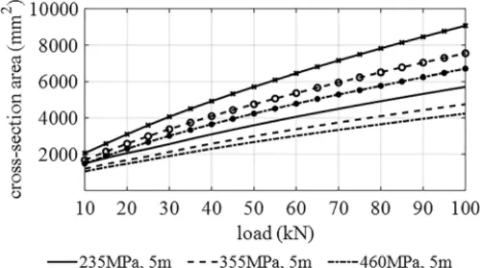
For the steel, the optimum results are as follows using different steel grades and span length. The heat input is 60.7 (kN/m3).
Figure 3 shows that the cross-section is near linearly proportional to the loading, but the increment depends on the span length. If one double-span length, the cross-section, so the mass of the beam does not double. Using higher strength steel, one can save material. The material savings are 21.4 % using fy 355 (MPa) instead of 235 (MPa) and 31.4% usingfy460 (MPA) instead of 235 (MPa) steel.
For the aluminum, the results are as follows using different alloys.
Figure 4 shows that the cross-section is linearly pro- portional to the loading using aluminum, but the increment depends on the span length. The applicable load is limited; it cannot go up to 100 (kN).
At the lighter aluminum, the stability constraint has a high effect on larger span length. Using higher strength aluminum, one can save material. The material savings are 54.5% using fy 155 (MPa) instead of 90 (MPa) and 64.8%
using fy 230 (MPa) instead of 90 (MPa) aluminum. For larger span length, the optimum cross-section value is jumping due to the local buckling limit.
Having smaller heat input for steel, 12.5 (kJ/m3) the tendency is different. The cross-section areas increase not linearly, but smaller, applying larger loads (Fig. 5). The effect is similar to aluminum, with 14 (kN/m3) heat input (Fig. 6).
The heat input depends on the voltage, current, welding speed, and the welding technology’s efficiency. In most cases, the applied current and the welding speed can be changed. For smaller energy input, the results are different for both materials For higher heat input (Figs 7and8) give the results.
At the smaller heat input for aluminum, 14 (kJ/m3), the tendency is different (Fig. 6). There are solutions for L510 (m), when the force is increasing. The cross-section areas do not increase linearly, but smaller, applying larger loads. For the Al230 (MPa) at 10 (m), the cross-section is 22% less, when the heat input went down from 46 (MPa) to 14 (kJ/m3).
Fig. 3.Optimum results for different steel grades and span lengths, heat input is 60.7 (kN/m3).
Fig. 4.Optimum results for different aluminum alloys and span lengths, heat input is 45 (kN/m3)
Figure 7 shows that the different steel grades are still applicable for larger span-lengths using higher heat input (higher current or lower welding speed). For aluminum, this is not the case.Figure 8shows that increasing the heat input;
the maximum applicable load values are very limited. ForAl 90 (MPa), 10 m it is only 20 (kN).
8. CONCLUSIONS
This article has presented the calculation to determine the optimum dimensions of asymmetric I-beams for minimum shrinkage. The welding shrinkage is always larger at asym- metric than symmetric beams. The objective function is the minimum mass; the unknowns are the I-beam dimensions;
the constraints are the stress, local buckling and deflection.
Different steel grades have been considered (235, 355, 460 MPa yield stress) and different aluminum alloys (90, 155, 230 MPa yield stress). The material, the span length and the loading have been changed. It is shown that using pre- bending, welding shrinkage can be eliminated, and using optimum design, the material cost can be saved as well.
During optimization the minimum sizes of the asymmetric I- beam have been calculated. The design constraints were the static stress, local buckling of the web, flange and pre-bending to eliminate shrinkage. The material (steel, aluminum), the yield stress (235, 355, 460 (MPa) for steel, 90, 155, 230 (MPa) for aluminum), the span length (5 (m), 10 (m)) and the heat input (for steel 12,5; 60,7; 91,8 (kJ/m3), for aluminum 14;
45;61,2 (kJ/m3)) have been changed and compared.
The cost-saving for different steels is up to 31.4% and for other aluminum is up to 63.8%. Various steel grades are more applicable for more considerable heat input and larger span-lengths. With these calculations welding shrinkage and mass of the beam can be reduced as well.
ACKNOWLEDGEMENT
The research was partially supported by the Hungarian National Research, Development and Innovation Office under the project number K 134358.
REFERENCES
[1] M. Urner, T. Welters, and K. Dilger,“Calculation of welding re- sidual stresses and distortions under complex process conditions, Fig. 5.Optimum results for different steel grades and span lengths,
heat input is 12.5 (kN/m3)
Fig. 6.Optimum results for different aluminum alloys and span lengths, the heat input is 14 (kN/m3)
Fig. 7.Optimum results for different steel grades and span lengths, heat input is 91.8 (kN/m3)
Fig. 8.Optimum results for different aluminum alloys and span lengths, heat input is 61.2 (kN/m3)
Fabrication and Economy of Welded Structures, K. Jarmai, J.
Farkas, Eds., International Conference Proceedings, Miskolc, Hungary, Apr. 24–26, 2008, 2008, pp. 395‒402.
[2] H. Wohlfahrt, T. Nitschkepagel, K. Dilger, D. Siegele, M.
Brand, J. Sakkiettibutra, and T. Loose, “Residual stress calcu- lations and measurements–Review and assessment of the IIW round robin results,” Weld. World, vol. 56, no 9–10, pp. 120–140, 2012.
[3] A. Kawaguchi, S. Itoh, M. Mochizuki and M. Kameyama,“Large- scale computation of welding residual stress,” Prog. Nucl. Sci.
Technol., vol. 2, pp. 613–619, 2011.
[4] K. Jarmai and M. Petrik, “Optimization and comparison of different standards for compressed welded box columns,”Pollack Period., vol. 15, no. 1, pp. 3–14, 2020.
[5] Z. Virag, “Determination of optimum diameter of a welded stiffened cylindrical shell,”Pollack Period., vol. 4, no. 1, pp. 41–52, 2009.
[6] K. Jarmai and R. Sz}ucs,“Investigation of welded protective covers for heat treatment,”Pollack Period., vol. 15, no. 1, pp. 15–26, 2020.
Fabrication Technology of Welded Structures(in Russian). Lenin- grad: Sudpromgiz, 1963.
[8] V. A. Vinokurov,Welding Stresses and Distortion: Determination and Elimination (Translated from Russian). British Library Lending Division, 1977.
[9] K. Masubuchi,Analysis of Welded Structures. Oxford: Pergamon Press, 1980.
[10] S. A. Kuzminov, Welding Deformations of Ship Structures (in Russian). Leningrad: Sudostroenie, 1974.
[11] J. Farkas and K. Jarmai,“Analysis of some methods for reducing residual beam curvatures due to weld shrinkage,”Weld. World, vol. 41, no. 4, pp. 385–398, 1998.
[12] J. D. White, “Longitudinal shrinkage of a single pass weld,” Technical Report, No. CUED/C-Struct/TR.59 c, Cambridge Uni- versity; Department of Engineering, 1976.
[13] G. P. Wozney and G. R. Crawmer,An Investigation of Vibrational Stress Relief in Steel. Defense Technical Information Center, 1968.
[14]Eurocode 3, Design of steel structures, Brussels, CEN 2009.
[15]Eurocode 9, Design of aluminum structures, Brussels, CEN 2007.
Open Access. This is an open-access article distributed under the terms of the Creative Commons Attribution 4.0 International License (https://creativecommons.org/
licenses/by/4.0/), which permits unrestricted use, distribution, and reproduction in any medium, provided the original author and source are credited, a link to the CC License is provided, and changes–if any–are indicated. (SID_1)