An International Journal for Engineering and Information Sciences DOI: 10.1556/606.2020.15.1.2 Vol. 15, No. 1, pp. 15–26 (2020) www.akademiai.com
INVESTIGATION OF WELDED PROTECTIVE COVERS FOR HEAT TREATMENT
1 Károly JÁRMAI*, 2 Renáta SZŰCS
1 University of Miskolc, H-3515 Miskolc, Hungary, e-mail: jarmai@uni-miskolc.hu
2 S&G Solution Ltd. H-3532 Miskolc, Hungary, e-mail: renata.szucs@sg-solution.hu
Received 2 January 2019; accepted 23 September 2019
Abstract: A welded steel protective cover used for the heat treatment of steel sheet coils is investigated. The protective cover is made of austenitic stainless steel and consists of three main segments, welded together, which have 1400 mm height each. The plate thicknesses at the lower, middle and upper segments are different. The investigation aimed to improve the lifetime and the number of heat cycles of the protective cover by changing the geometry, the effect of the thicknesses and the material. Damaged covers have been evaluated, made calculations of stress and deformations, and carried out a series of finite element simulations. Both horizontal and vertical corrugated sheets were simulated and compared. The non-corrugated plates were also investigated, but their performance was behind the corrugated ones. The original geometry and that of the horizontal corrugated plate are identical from the stress level point of view. The vertical position of the corrugated plate provided a better result than the horizontal one. The calculated and simulated results for the original geometry are close to the measured damage.
Keywords: Welded protective covers, Heat treatment, Stability, Local buckling
1. Introduction
There are several publications for heat treatment, but for this kind of structure it is not available. In this article the classical horizontally corrugated and the newer vertical corrugated covers are investigated and compared. A new version is a vertically bent plate, where more geometries have been investigated.
* Corresponding Author
Description of the process: Protective covers are employed in the heat treatment of steel sheet coils. They become damaged after several heat cycles.
Description of the heat treatment process: Heating to 520-720 °C, keeping this temperature constant for 14-24 hours, cooling with water. The total time cycle of heat treatment is 68-70 hours.
Description of the problem: Due to the heat effects to which they are subjected during the heat treatment process, the protective covers are damaged earlier than the expected lifetime.
The current layout of the protective covers: The protective covers are made of austenitic stainless-steel No. 1.4571. The original surface is horizontally corrugated.
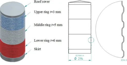
This wavy surface can be seen in Fig. 1 and Fig. 2. The protective cover consists of 3 main segments, each with a height of 1400 mm height. Less or more segments are not economical due to the welding cost. The plate thickness t of the lower segment is 6 mm, the middle segment 5 mm, and the upper segment 3 mm. When segments meet, their thicknesses are different; the interior flush shows the difference of 1 or 2 mm. The diameter of the original protective cover is 2150 mm, at the lower segment of the protective cover there is a skirt, and a slightly conical shell covers it at the top (Fig. 1).
The protective cover is made of a wave-like form plate, as it is shown in Fig. 2.
Fig. 1. The current geometry of the
protective cover
Fig. 2. The geometry of the protective cover
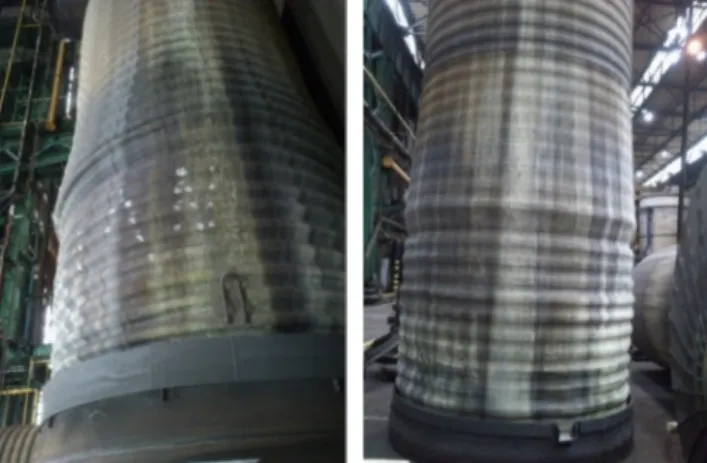
Damage: Generally, the protective covers are damaged in the lower part of the middle section (see Fig. 3). At this part the waves are deformed, material softening occurs and the original form is lost.
The aim: Investigation of the original corrugated protective cover is carried out to find the reason for the damage and the new versions are investigated to compare their predicted lifetimes.
Fig. 3. Some damage to the protective cover
2. Strength calculation of the protective cover
The protective cover is used for the softening of steel sheet coils in safety gas. It is heated by gas from outside up to 1100 °C. The protective cover acts as a chamber for heat treatment. The heat convection is carried out by the protection gas from outside of the wall of the protective cover. The cover is placed in a special chamber. It is kept at 520-720 °C for 14-24 hours. The time cycle of heat treatment is 68-70 hours.
The corrugated cylindrical protective cover is made of heat resistant WNr 1.4571 type steel. The three segments are horizontally welded together. The diameter of the protective cover is 2R = 2150 mm. The height of each section is L = 1400 mm. The thickness of the lower segment is 6 mm, of the middle segment is 5, and the upper segment is 3 mm. The inner and outer diameters of the wave are 2150 and 2174 mm.
The wave consists of two intermediate sloping segments and a mid-section with a 40 mm high straight line.
At the top of the protective cover there is a conical roof with 150 mm height and 3 mm thickness. The parameters of the protective cover material are as follows [1]:
X6CrNiMoTi 17-12-2 austenitic steel, density 8 kg/m3, tensile strength 520-670 MPa, 0.2% elongation limit, min Rp0.2 =220, elongation at break is 40%. Young’s modulus at room temperature is E = 2.1·105 MPa, at 1100 °C, E1 = 0.0225·210000 = 4725 MPa.
The Poisson ratio is 0.3.
The typical failure of the cover was the deformation of the wave at the bottom of the middle segment. Therefore, the purpose of the research is to assess the strength of the waves in the steel.
2.1. Loading of the corrugated plate at the lower part of the middle segment
The dead load of the protective cover is calculated at the lower part of the middle segment, which is the most critical.
The volume of the slightly conical roof
2 2
2 + ℎ
3 1075√1075 + 150 10.9928 · 10!, (1)
the mass m = ρV=8·10.9928 = 88 kg.
The volume of the middle and upper segment together, considering average radius Ravr is as follows:
# 2 $%& ℎ#'#+ ( 2 · 1081 1400'3 + 5( 76.07 · 10!, (2) the mass m1 = ρV1=8·76.07=609 kg.
The total value of the dead load acting on the lower part of the middle segment is
88+609=697 kg. (3)
The uniformly distributed dead load on the perimeter is
+ .# -/!,- 1.032 N/mm. (4)
2.2. Stresses in the corrugated plate
The dead load has compression and a bending effect with 12 mm arm length. The normal stress from compression and bending is as follows:
01+ 0 #. 2/ +#. 2 ·#/3/! 0.2064 + 2.9716 3.17856 MPa. (5) The corrugated protective cover has bent from the temperature difference between the outer and inner sides. The thermal expansion of the inner wave radius is calculated as follows: ∆Ri=α0∆TiRi, the outer wave radius is ∆Ro=α0∆ToRo, the difference between these two is:
5 6− 5 8 '598 8− 596 6( 12 ⋅ 10;!'1100 ⋅ 1087 − 720 ⋅ 1075(
5.06 mm. (6)
The ρ dead-load has this arm length and bending moment and the calculated stress is as follows:
0 # #. 2 ·/. !
/3/! 1.2533 MPa. (7)
The value of total stress assuming elastic stress distribution is
01+ 0 + 0# 4.432 MPa. (8)
2.3. Damage of the corrugated plate
Because there is not given the yield stress of the material, it was difficult to calculate the damage caused by yield point. As an approximation, the stresses were considered in the wave to be elastic at 1100 °C. The strain of the edge line using E1 = 4725 MPa value for Young’s modulus is
? @.@2@- / 9.38 ⋅ 10;@. (9)
It is assumed that this strain is repeated until damage occurs. The limit strain was considered at tensile strength. The number of thermal cycles is as follows:
.@
,.2A⋅# BC 426. (10)
This means that the corrugated plate can have roughly 426 thermal cycles with a limited value of damage. Calculate 20 hours for heating up and keeping at temperature.
It means 8,500 work hours. Limit strain of the material is 40% at 1100 °C.
2.4. Investigation of the corrugated protective cover
Local buckling may occur at the wave-less part of the circular plate. Considering the 1100 °C temperature, the critical buckling stress is fy = 0.02·350= 7 MPa, using E1 = 4725 MPa Young’s modulus and approximated yield stress. The critical stress for shell buckling according to the design guide of Det Norske Veritas (DNV) [2] is the following:
0D& EF
#GHC, J KLEFM, (11)
0N '1.5 − 50O(# '#;RP.3N3Q( SUTV , (12)
W 1 + 'X Y( , X 0.5 S1 +#/ TZ V; ./, Y 0.702[, [ Z\U3√1 − . (13) The shortening of the radius because of the reduction of the circular weld is calculated according to β following the suggestions of [3]
O ]@√ZT^_`, ab$c 0.64d\KZT, d\ 0.844 ⋅ 10;2 eTf, (14) the heat input at the butt weld
g\ 60.7 dh, dh 10, (15)
where umax is the shortening of the radius, AW is the cross-section of the circular butt weld, QT is the weld heat input.
Data are as follows:
the Poisson ratio ν=0.3; t = 6 mm; R = 1075 mm; L = 1400 mm; the critical stress
σcr=3.488 MPa. (16)
Stress comes from the dead load 01# #. 2
! 0.172 MPa. (17)
It is visible that σn1 << σcr so the 6 mm thick wave free shell is protected against local buckling.
2.5. Polygonal cover analysis - plate buckling at high temperature
The question is how long should the sheet cover between the corners be so as not to buckle at high temperature?
The classical equation for sheet buckling is as follows:
0D& i.3N
# '#;R3(STjV , (18)
where k is the buckling parameter, the plate is simply supported, the loading is uniform compression: k = 4, ν = 0.3 the Poisson number, b is the width of the plate.
According to Eurocode 3-1-5 [4] there is no need to calculate the effective width if
Jk KLElmF ≤ 0.673. (19)
From Eq. (18)
0D&≥ .!-2EF 3. (20
Combining equations (18) and (20)
j
T≤ 0.40732KENFKELF, (21)
where using Eq. (3) values
0 !,-1jT. (22)
3. Finite element simulation of the protective cover
Since b is unknown in Eq. (22), the determination of b is done by iteration, the approximate value is
0 p!,-Z.T. (23) If b is known, the n-angle cover n value can be calculated from the following equation
q 2 #A1r. (24)
In this case from Eq. (23) σ = 0.172 MPa, from Eq. (21) b = 405 mm, the number of n = 16.6, rounded to n = 18. With this value b = 373 mm, from Eq. (22), σ = 0.173 MPa from Eq. (21), b = 403.9 > 373, so there is no buckling using n = 18 polygon cover at 1100 oC.
Naturally, measurements and calculations are made in the field of optimization of systems and structures [5]-[7]. Also, during the process of finding the optimum shape, finite element calculations are needed [8], so a systematic search was carried out on the possible configurations to simulate this behavior and to select the best geometry. Finite element analysis was carried out using the software ANSYS.
During the examination the original shape and the new shapes are compared to each other using the same boundary conditions. At the lower segment of the protective cover, at the sand bed, in the protective cover axis direction the deformation is zero, in the other two directions deformation is allowed. Loading comes from the dead load. The temperature of the covers is uniformly 660 °C. During the calculation the stress state and the deformation were analyzed.
3.1. Analysis of the original protective cover
The original protective cover can be seen in Fig. 1 and Fig. 4. Simulations were carried out using the given load and boundary conditions and the mesh shown in Fig. 4.
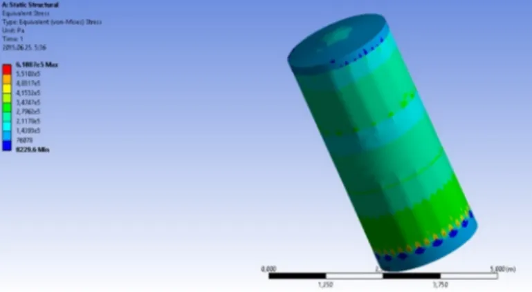
Fig. 5 and Fig. 6 show the normal stress of the original protective cover in general and in details. In Fig. 6 it is visible, that the stresses are larger at the lower parts of the protective cover’s three segments. The largest is at the lower part of the lower segment.
Fig. 4. The mesh of the original protective cover
The results of the FEM calculations (Fig. 5 and Fig. 6) show good agreement with manual calculation at the critical point ~2.5 MPa, which is at the lower part of the middle segment of the protective cover.
Fig. 5. Normal stress
Fig. 6. Normal stress details
Remarks
The results of the previous study support the findings of manual calculations and are consistent with the actual damage. Based on the analysis, the highest stress and deformation occur in the lower parts of the different segments, where the dead load is the highest at a given thickness. There are three thickness steps, and the thicknesses are increasing from the top to the bottom.
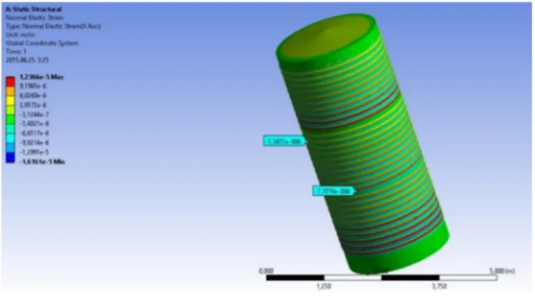
The dead load is continuously increasing from the top to the bottom. That is why the critical parts are the lower parts of the segments. The most critical is the middle segment because stress and deformation are more significant not only at the peak of the wave but also in its surroundings, and the values is higher compared to those in other sections (see Fig. 7).
Fig. 7 shows the normal strain distribution. It is visible that the lower parts of the three segments are in danger. These agree with the normal stress distribution, where the stresses are higher, there is more chance to have damage.
Fig. 7. Normal strain
3.2. Vertical waveform
In the next structural layout, the trapezoidal waveform is used, but the position is different, as the waves are placed vertically and not horizontally (see Fig. 8). The thickness of each section is 6, 5 and 3 mm, from bottom to top. Boundary conditions are as described earlier.
Remarks
The finite element computations show that the protective cover with vertical waves is useful and the strength of the protective cover is more considerable. Unfortunately, there is a substantial drawback: joining the different segments with different thicknesses is difficult, having not a cylindrical joining line as earlier, but a corrugated one (Fig. 8, Fig. 9).
Fig. 8. Mesh of the cover Fig. 9. Normal stress
3.3. Bent plate
The next versions are bent protective covers. Four different bent protective covers are employed, arranged as shown in Fig. 10. The difference between them is the number of bents on a given diameter. The following types were used in the simulation:
• Type 17 (17 bents);
• Type 23;
• Type 34;
• Type 67.
Fig. 10. The bent plate geometry in general
The first three types have been investigated because for manufacturing considerations the last type (67) is not optimal. Also, the smaller number of bents reduces the inner area, which is needed for the treatment. First, the three models are compared to each other. The plate thicknesses are identical: 6, 5, 3 mm at the lower, middle and upper segments. The end conditions are according to the previous ones (Fig. 10), which means that the skirt is in the sand bed representing a pinned support.
The finite element calculation was carried out for types 17, 23 and 34. The equivalent stress, the equivalent elastic deformations are shown for type 17 (Fig. 11), for type 23 (Fig. 12), and for type 34 (Fig. 13). In all cases, the most critical is the lower part of the different segment, especially the lowest one. Due to the segment thickness value, the mesh is coarser at the thicker section.
Fig. 11. Equivalent stress for type 17
Fig. 12. Equivalent stress of type 23 Fig. 13. Equivalent stress of type 34
Remarks
The simulation shows that the maximum equivalent stresses for the type 17, 23 and 37 are 0.62, 0.92 and 0.89 MPa respectively. The maximum equivalent elastic deformations are 3.15, 4.76 and 4.58·10-6 respectively. Comparing the FEM results of the three versions and taking into consideration manufacturing aspects (more bents more manufacturing needed), Type 17 is the best solution because the stress is the smallest, and less manufacturing needed. Type 23 and type 34 are also suitable, but they need more manufacturing, having more bents.
4. Conclusions
A welded steel protective cover is investigated, which is used for the heat treatment of steel sheet coils. Protective covers are made of austenitic stainless steel. The investigation aims to improve the lifetime (the number of heat cycles withstood) of the protective cover through changing the geometry, using the same thicknesses and material. The damaged sheets have been evaluated by the calculations on stress and
deformations and investigated a series of finite element models. The original geometry and the horizontal corrugated plate are identical from the stress level point of view, even if the wave geometries were slightly different. The vertical position of the corrugated plate gave better results than the horizontal one. Using vertical corrugated plates is not economical, because the manufacturing is more complicated at the joints of the segments. The result of the original geometry is close to the measured damage.
Vertically bent plates have been investigated. Their strength is higher, than the horizontally corrugated covers. The smallest equivalent stress belongs to type 17 protective cover, the type 23 and type 34 are also suitable, but they need more manufacturing, having more bents.
Further increase of the lifetime may require the application of a better steel grade.
This effect can be validated by experiments, using thermal resistant steel instead of the stainless steel currently used. Whatever kind of steel grade is used, it is essential to verify the effect of geometrical or material changes through experiments.
Open Access statement
This is an open-access article distributed under the terms of the Creative Commons Attribution 4.0 International License (https://creativecommons.org/licenses/by/4.0/), which permits unrestricted use, distribution, and reproduction in any medium, provided the original author and source are credited, a link to the CC License is provided, and changes - if any - are indicated. (SID_1)
References
[1] Inox Service Hungary: Stainless steel material properties and their use.
http://www.inoxservice.hu/index.php/hu/anyagtulajdonsagok, (last visited 3 December 2018)
[2] Buckling strength of shells, Recommended Practice DNV-RP-C202, Det Norske Veritas, 2002.
[3] Farkas J. Thickness design of axially compressed unstiffened cylindrical shells with circumferential welds, Welding in the World, Vol. 46, No. 11-12, 2002, pp. 26‒29.
[4] Eurocode 3, Design of steel structures. Part 1-5, Plates structural elements, 2007.
[5] Kota L., Jármai J. Efficient algorithms for optimization of objects and systems, Pollack Periodica, Vol. 9, No. 1, 2014, pp. 121‒132.
[6] Virág Z. Optimum design of stiffened plates, Pollack Periodica, Vol. 1, No. 1, 2006, pp. 77‒92.
[7] Varga T., Szepesi G., Siménfalvi Z. Horizontal scraped surface heat exchanger - Experimental measurements and numerical analysis, Pollack Periodica, Vol. 12, No. 1, 2017, pp. 107‒122.
[8] Berezin I. M., Petunin A. A., Kryuchkov D. I., Kovács G. L. Finite-element simulation of the cold stamping process of spherical vessels, Pollack Periodica, Vol. 12, No. 1, 2017, pp.
81‒92.