MOMENTUM VECTOR CONSIDERATIONS IN WHEEL-JET SATELLITE CONTROL SYSTEM DESIGN
D. B. DeBra and R. Η· Cannon, Jr. 1 2 Lockheed Missiles and Space Co., Sunnyvale, Calif.
ABSTRACT
The preliminary design problem of sizing wheels and a gas supply for a long term satellite attitude control system is discussed, with emphasis on the distinction between cyclical and secular changes in momentum. Torques which vary in magni- tude as a function of orbital radius and anomaly, and whose orientation is fixed either in the satellite or in inertial space are discussed in general. Specific cases are examined for gas-leak, gravity, and aerodynamic torques. Of special interest is the set of sinusoidally varying torques needed on individual spinning parts inside a local vertical satellite to maintain the total stored momentum vector of the aggregate fixed in inertial space while the satellite rotates around it.
Some advantages of applying dynamic-decoupling techniques are demonstrated. In particular, it is shown that, for a reaction wheel controlled satellite without decoupling, a steady
sinusoidal error persists so that an excessively tight control system may be required to meet performance specifications.
With decoupling control the errors are zero, but a certain level of sinusoidally /arying torque is required on individ- ual spinning parts so long as: l) a local vertical (or other rotating) reference is sought, and 2) single-axis reaction wheels or gyros are used as actuators. The reaction sphere avoids this requirement, in principle.
INTRODUCTION
The design of an attitude control system requires a torque source for effecting change in attitude. In space vehicles it is common to use a dual source of torque ; typically a set of flywheels and a set of small jets. The former act as a
Presented at ARS Guidance, Control, and Navigation Conference, Stanford, Calif., Auge 7-9, 1961·
^Senior Scientist; also at Division of Engineering Mechanics, Stanford University, Stanford, Calif.
Associate Professor of Aeronautics and Astronautics, Stanford University, Stanford, Calif.
momentum storage device and the latter as a. means of trans- ferring momentum away from the vehicle. In this paper the authors will discuss the preliminary design aspects and the dynamic response of some simplified control systems using these combined torque sources.
Jets have a much greater maximum momentum change capa- bility for a given total mass of propellant and equipment needed to produce the torque. That is, for a constant torque acting on the vehicle, a wheel system will saturate (he accel- erated to its maximum speed) much sooner than a jet control system of the same overall mass.
However, once the propellant of a jet system has been expelled, there is no way to get hold of this mass to acceler- ate it again. In the presence of a cyclic torque, therefore, a jet system uses propellant continuously. On the other hand, momentum storage devices such as wheels can be accelerated back and forth indefinitely. When used together, these systems
complement each other. Cyclic and short term changes in momentum are stored and steady changes in momentum are period-
ically expelled by the jets.
A space vehicle is acted on by external torques. These torques all change the angular momentum of the vehicle. It is the job of the control system to apportion the total momentum of the system so that the control parts of the vehicle store exactly the amount not needed by the vehicle to perform its mission. Since most external torques act directly on the vehicle and not the storage devices, in a. broad sense attitude control may be thought of as momentum transport. Some momen- tum may be stored in parts and some expelled. The means of transporting the momentum is of course the control torques, with the torque and momentum being related by Newton1s second law of motion.
This point of view is hardly astounding, but its implica- tion on the reference frame from which control must be viewed is of paramount importance. Newton's law is valid only in inertial space, so when one speaks of constant torque causing a steadily increasing momentum change, it is implicit that this torque is constant wrt (with respect to) inertial space.
It is perfectly admissable to speak of torques which are constant wrt non-inertial frames. For example, Roberson (l) has given several examples of torques due to moving parts in a vehicle rotating at constant angular velocity. If a small mass vibrates along a vehicle axis skewed to the angular
velocity, it produces a torque which is constant wrt the vehicle.
But one must use caution in drawing any conclusions as to the effect of such torques. The incautious reader may in- correctly conclude this is equivalent to a constant external torque. But a constant external torque is constant wrt inertial space and the total momentum change of the system must increase linearly with time, while the angular momentum
of any system of masses, whether vibrating or not, is constant in the absence of external torques.
It is not intended to pursue this point further. However, it is fundamental and the most important single idea used in the preliminary design process which consists of computing the momentum storage capacity needed for storage devices and the total momentum change capability required of a jet system.
It is also important in understanding how stored momentum must be handled.
To demonstrate this point of view, some examples are worked out. The effects of several external torques are con-
sidered first and then the response of two simple control systems are compared.
PRELIMINARY DESIGN CONSIDERATIONS : DISTURBING TORQUES AND SLEWING REQUIREMENTS
In choosing a control torque source for a control system one is usually interested in the torque level that must be achieved under the worst conditions. Space vehicles generally do not require large torques (except during the translational acceleration of ascent). Rather, it is usually the time integral of torque that is hard to counter and which must be considered in sizing a satellite attitude control system.
Here, preliminary design will consist simply of determining the momentum change corresponding to external torques acting on the vehicle or to slewing requirements.
The maximum momentum storage needed to absorb the effect of torques that produce purely a cyclic momentum change can be conservatively estimated by assuming the maximum value acts for one half the period.
Only a torque which is constant wrt inertial space will be referred to as a. constant torque. The secular momentum
change due to a constant torque is
ΔΪ? = t At [ 1 ] The problem is that torques do not generally produce effects
that are either purely cyclic or purely secular, and it is necessary to work with the total impulse produced by the torque, i.e., by its time integral
^ death _^
ΔΗ = j L dt [2]
birth
For illustration, a torque is considered whose magnitude varies with radius and/or the true anomaly and whose orientation is fixed in a local vertical frame or fixed in inertial space.
In order to integrate wrt time, the torque must be expressed in inertial coordinates as a function of time (or the mean anomaly). Most classical texts devote a chapter to this problem; e.g., see Smart ( 2 ) . Alternatively it is possible to convert the variable of integration. For example, dt can be written
dt = dA/Â [3]
where  is expressed as a function of A, the true anomaly.
The torque must be transformed to an inertial space if it is expressed in any other coordinate frame. If the torque is fixed wrt inertial space, then only the magnitude need be con- sidered. In general if the torque is oriented to a reference comprised of the local vertical and the normal to the orbit plane the transformation to inertial space is
L. = Γ 1 . ^ [k]
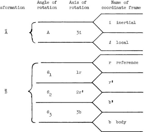
where A transforms coordinates from an inertial space to a local reference frame. In this section on preliminary design, attitude dynamics are ignored. Therefore the local reference frame is also the body frame. See Table 1 and Fig. 1 .
It is usually easier to avoid the expansion in the mean anomaly by using for example, Eq. ( 3 ) . Once the components are written in inertial space, the integration may be carried out for each component. For the coordinates of Fig. 1 the general expression obtained is
ΔΗ. = ι
L. dA ι
h(l+e cos A ) '
cos A sin A
- sin A cos A
0 0 0 1
[ 5 ]
'L.dA
As examples of this procedure the effects of gas leaks, gravity torques, and aerodynamic forces will he considered because these generally cause torques that act in different ways. An ideal model will be used to study these effects. It will be assumed that the satellite is in orbit about a spherical non- rotating Earth; that the aerodynamic forces can be calculated from a model exponential atmosphere with scale height d; and that free molecular flow can be approximated by Newtonian flow in which the momentum change of molecules (devoid of random motion) is taken into account as they hit the vehicle but not
as they leave the vehicle surface. It is further assumed the control system is sufficiently tight that the satellite is oriented without error with respect to the reference coordinate frame (b = r ) .
Gas Leak Torque
If gas leaks from a satellite, it can cause a torque the components of which are constant in a body coordinate system.
For an inertially fixed vehicle the torque is constant and the integration is trivial. The torque causes a purely secular change in momentum and Eq. (l) can be used. If the vehicle is oriented wrt a local frame it is necessary to transform the components to an inertial frame which gives.
(b = r = i)
L^cosA - L^sinA 0
-L2 Ll
L^sinA + L^cosA = 0 +
Ll sinA + h
L, L, 0 0
3 3
[6]
The change in momentum caused by this torque is the time integral of the torque coordinatized in inertial space; how- ever, the torque components are a function of A, the position of the satellite in its orbit, as a result of the transforma- tion of coordinates. Integration can be carried out with
respect to time, to the true anomaly or with respect to the eccentric anomaly. Gas torques supply an example of each.
The first term of Eq. (6) is, of course, simply integrated with respect to time. The second term can he integrated with respect to the true anomaly,' however, the third term is most easily integrated by converting to the eccentric anomaly. The integrals then become
ΔΗ = dt + ρ sin A dA
h(l+e cos A)'
(cos E-e) dE
η : 7 i
with the result 0~ ~-L "
2
ΔΗ = 0 +
Ll
V
0V
he(l+e cos A)
A r- -,
t 1
+ L
2
0 A^ 0
0
sin E-eE η
[8]
This example also emphasizes that the limits of integra- tion must be used or some terms may be misinterpreted. It may be noted that the form of the second term is
l/e(l+e cos A) [9]
and this expression becomes large as the eccentricity gets small. However, the change in momentum is a change between limits in time, and hence the integral must be evaluated between limits. However, when the limits are introduced, an expression of the following form
(cos Aq - cos A )/(l+e cos AQ)(l+e cos A ) [10]
is obtained for which no difficulty is encountered as the eccentricity becomes small. It will be understood in what follows that limits are implicit even when omitted.
Dividing the results into secular effects and cyclic effects gives the momentum change as
(b = r = i)
-> -eL E/n
L2 ΔΗ. =
1
-eL2E/n + -Li
0
Ln 1 L 2
m 0
(cosA^ cosA^)p^
h(l+ecosAQ)(1+ecosA^)
sin Ε
η [ 1 1 ]
When a term appears involving A or Ε linearly, it represents a secular change wrt time plus a cyclic term that comes from the expansion of A or Ε in terms of time (the mean anomaly) . The cyclic terms will he of order e com- pared with the secular term. Any term that increases mono- tonically with time will he referred to as a secular change, even though it involves cyclic components.
The actual secular effect can he identified by computing the ΔΗ per orbital revolution. The secular change in Eq.(ll) per orbital revolution becomes
ΔΗ./Ν - — r η
-eL.
-eL. [ 1 2 ]
where N is the number of orbital revolutions.
Gravity Torque
The gravity torque acting on a rigid body can be expressed by the following equation derived in (3)
L = 3k R X I-R/R" [ 1 3 ]
It can be seen from Eq. ( 1 3 ) that the torque is zero when a principal axis of the vehicle^is aligned with the local radial direction. That is, if R is an eigenvector of
I, I»R is in the direction of R. When this is crossed with R the result is, of course, identically zero. The designer may attempt to make the reference position of the vehicle control system correspond to a set of principal axes aligned with the local coordinates. He is only able to place his
sensors wrt axes which are located within the "body, and these may not correspond to the principal axes. is then con- stant hut not necessarily diagonalized and there is then a torque of the following form
(h = r = $,)
5k R 3
0 -I 3 1
21
[14]
Transforming this to inertial space using Eq. (5) and integra- ting one obtains
(b = r = i) i)
0
-I5 1eA/2 +
Λ -I (cos A+e cos 2A/4)
-I5 1(sin A+e sin 2A/4) > [ 1 5 ]
The secular term in the third component is to he expected, hut it is important to note that the second component has a
secular term of order e. This term results from sychronous rectification. In an eccentric orbit the vehicle stays longer near apoapsis, hut the torque is enough smaller to offset this and a secular momentum change results which has the same sense as the torque at periapsis. There is no component of the average torque impulse along the line of apsides because of the symmetry about it.
If the vehicle is fixed in inertial space, 1^ is con- stant. Obtaining R. and expanding the torque from Eq. ( 1 3 )
it is x
(b = r - i) r
= 5k
" R3
( I5 1 s i n 2A + I - I cos 2A)/2 - ( X - + I__ cos 2A + I _ s i n 2A)/2
3 1 3 1 32 1
I )sin 2A/2 I2 1 cos 2A + ( I2 2
[16]
It can be seen from the constant terms in the first two com- ponents of Eq. (16) that there will be secular terms in the momentum change even for circular orbits unless one principal axis of the vehicle is normal to the orbit plane. If R is expanded, additional cyclic terms appear which are of order e.
3
Combining R and A
l/(R5A) = 1/Rh = (1+e cos A)/ph [IT]
Combining Eqs. ( 5 ) , ( l 6 ) and (17)> a coefficient 3^/hp can be brought out of the integral and each component of Eq. ( l 6 ) can be multiplied by (l+e cos A) before integrating. Then
(b = r = i)
ΔΗ = ~ hp
5k hp
( - s i n 2A/2+e s i n A/2-e s i n 3A/6)/2 - I^ C c o s 2A/2+e cos A/2+e cos 3A/6)/2
3 2
(cos 2A+e cos A+e cos JA/j)/k
- I5 1( s i n 2A/2+Je s i n A/2+e s i n 3 A / 6 ) / 2 I ( s i n 2A+e s i n A+e s i n 3A/3)/2
+ ( Ιη- Ι2 2) ( c o s 2A+e cos A+e cos 3Α/3)Λ [18]
In this case the eccentricity does not effect the secular terms which have been separated out in Eq. ( l 8 ) ·
Aerodynamic Torque
To obtain an estimate of the aerodynamic torque a Newtonian flow is assumed with C^ = 2 and an exponential atmosphere with scale height d. More exact models of the free molecular flow are not generally needed for this type of preliminary design. (Schrello ( 7 ) gives a more sophisticated method of obtaining torques than is used here.)
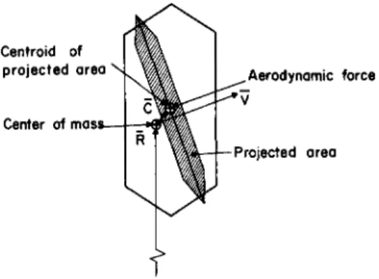
If^the centroid of the projection of the frontal area S is at C, wrt the center of mass (see Fig. 2 ) , the momentum change is
- > —»
ΔΗ = / L dt = / (C χ V) (-CdSpV2)R2.dA/2h [ 1 9 ] It is necessary to expand some of the expressions before integrating, since an exact integral cannot generally be obtained. First the density is written as a function of the true anomaly
ρ = p exp[-(R-R )/d] = ρ exp 7e Rp Λ / cos A-l V
\ d J \l+e cos A / [20]
then the following approximations are made to first order in eccentricity
R T = kp 2 2 l+2e cos A+e l+2e cos A+e cos A 2 2
« kp [ 2 1 ]
s i n = (l+e cos A)/(l+2e cos A + e2)1/2 « 1 [22]
Ρ ~L /P
cos β = e sin A/(l+2e cos A+e ) 1 « e sin A [23]
cos β e sin A sin β fa 1
0 0
[2k]
it is further assumed that S is constant and to first order -> -> /ν
C is fixed in the body. Then C χ V can be expanded in an inertial coordinate frame for two cases of interest. First, for a body fixed in a local coordinate frame
(h = r = 4)
[25]
Alternatively, if the body is fixed in an inertial space we get:
(b = r = i)
p
-C_(cos A + e sin A) 3
-C^tsin A - (e sin 2A)/2]
(^(cos A + e sin2 A)+C2[sin A - (e sin 2 A)/2]
[26]
It remains to expand density and integrate to get the effect Δ , . N
of the torque. Here the parameter α = (eR /d) is the significant size parameter to determine the type of expansions to use and its accuracy. When alpha is small, the exponential can be expanded in the familiar form
exp[-a(l - cos A)/(l+e cos A)] « l-a(l - cos A) + ··· [ 2 7 ] However, when alpha is large the effect of the atmospheric forces predominate near periapsis. The way in which the function behaves can be seen from Fig. 3 . In (5) the scale height is given as a function of altitude. It varies from 8 to 80 statute miles in the altitude range of 90 to 38Ο statute miles. Alpha is therefore greater than 1, for eccentricities greater than approximately 0.002 to 0.02 depending on the orbit size. Many orbits, therefore, initially have alpha greater than 1. The effect of drag, however, is to reduce the eccentricity so it is advantageous to have expansions for alpha greater than 1 and for small alpha.
( C x V ) ,
-C^(cos A + e sin A) 3
~C^[sin A - (e sin 2A)/2]
°1 " C2 8 S i n A
For small alpha, an expression for the momentum change to first order in OL and zeroth order in e is adequate. For a body fixed in local coordinates secular and cyclic effects are the first and second terms respectively of
(b = r = 4)
-> Sp kp i h
C^a A/2
-C (l-a)A
C [(l-a) sin A + (a sin 2A)/k]
C [-(l-a) cos A - (a cos 2A)/k]
-C a sin A
V [28]
If on the other hand, the body is fixed in inertial space the third component becomes
(b = r = i)
Δ Η5 ί = (Sp^kp/h) {[C^A/2] + [ (l-a) (^ sin A - C^ cos A)
+ a(C sin 2A - C2 cos 2A)/1+]} [29]
whereas the first two components are the same as for a body fixed in local space.
It can be seen from Fig. 3 that, for alpha greater than 1 0 , the secular effect of the torque can be estimated by integrating the constant value at periapsis between + the value of the true anomaly for which the torque is approxi- mately half the value at periapsis. When alpha is large the value of the true anomaly at which the aerodynamic force is reduced by r from its value at periapsis (typically r « 2)
A =cos"1[(a - log r)/(a + e log r)] [30]
or neglecting the term in e and assuming A is small one obtains
Ar « [(2 log r V a ]1/2 [ 3 1 ]
If an analytical expression for the torque near periapsis is desired the expansion in Eq. (27) can be used for small A.
The exponential part is
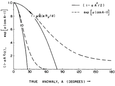
exp[-a(l~cos A)/(l+e cos A)] « l-aA2/2 [32]
It can be seen from Fig. k that this gives a good fit at periapsis, but even if it is integrated between the zeros of the quadratic function there is still a significant part of the area under the torque curve unaccounted for.
If the torque magnitude is assumed to be constant between + A^ and integrated between these limits the secular change in momentum per orbital revolution is approximated. Multiply- ing by the number of orbital revolutions, N, the secular momen- tum change is the same to second order in A for both
r locally and inertially fixed vehicles. Let
^ Sp kpN ΔΗ = — ?
There are various numerical and graphical ways of evalu- ating the effect. In specific cases, particularly when oc is of the order of unity or greater, these methods may be easier to handle and more accurate.
Momentum Exchange for Slewing
The total momentum of the system is unchanged in the absence of an external torque. However, the mission of the vehicle may require it to slew from one position to another or follow a nonuniformly rotating reference. In other words, the vehicle may have to borrow angular momentum from the storage devices. In addition to the cyclic changes and the buildup of momentum between operations of the gas system, the
storage devices must be able to loan the vehicle the necessary momentum for it to slew about; otherwise gas from the jet system is used inefficiently.
-2C_A 3 r
20. A 1 r
[33]
For simple changes in position the amplitude and time allowed determine both the torque and momentum requirements.
For example, if a vehicle is given constant acceleration for half its excursion and decelerated for the second half and the slew angle is φ, vehicle moment of inertia I and time allowed for the maneuver t , then the parts must loan a
m maximum momentum of
|ΔΗ| = 2lcp/tm [34]
and produce a torque
|L| = ^cp/t2 [35]
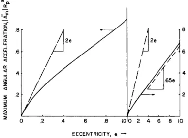
Another common requirement for a vehicle is to keep aligned to the local vertical. The momentum and acceleration requirements for this mission are summarized in normalized form in Figs. 5 and 6 . Eccentricities greater than 1.0 are included to cover reconnaisance-type missions to another planet. The maximum momentum of the vehicle body occurs at periapsis. The minimum occurs at apoapsis for an elliptic or- bit and is zero for parabolic or hyperbolic orbits. The momentum that must be loaned to the body is the difference between the maximum and minimum, which is
(e < 1 ) |ΔΗ| = [he/(I + e )3/2] Ι - χ ί ^ ^
(e > 1) |ΔΗ| = -χ/Γ^ I ΛΑΑ? [37]
The torque requirements are determined from the maximum angular acceleration of the local vertical. The acceleration is
A = - 2e sin A[ (l + e cos A)/(l + e ) ]3 k/R3 [38]
which extremizes at
A ν = c o smax Λ _ 1[( - 1 + -jï + kÔe2)/8e) [39]
The maximum magnitude always occurs between the true anomaly limits of 30° for an infinite energy hyperbola, and 90° for a circular orbit.
SIZING CONTROL ACTUATORS
The effects of the torques just considered is summarized in Table 2 . It should be noted that most torques give rise to secular as well as cyclic changes in the momentum. Con- verting these momentum changes into hardware requirements is done in the following way: Over the lifetime of the vehicle the net secular change in momentum must either be stored or expelled. As mentioned before, gas systems are more efficient when making a net momentum change. Therefore, the gas require- ments are normally computed on the basis of the secular momen- tum change plus whatever leakage and safety factors are necessary. To convert momentum change to gas requirements it is necessary to know the specific impulse of the gas jet system and the moment arm of the jet force with respect to the vehicle center of mass. Jet torque is then
—> - »
|L| = |r X FI < rmv = rwl [kO]
1 , 1 1 — ex sp
which causes a momentum change
|ΔΗ| = J/ L dt| < r m ve x = r w l ^ [kl]
where the total mass, m, of gas used in creating the momentum change has a weight at takeoff of w.
Normally the gas jets are operated intermittently; i.e., a certain amount of momentum is allowed to build up in the vehicle and then it is expelled by a short blast with the gas jet system. The storage devices must, therefore, store the secular change that occurs between expulsion as well as the cyclic momentum change. The maximum momentum that can be stored by a wheel can be expressed in terms of the wheel moment of inertia and the maximum speed at which the wheel
can be operated
ΔΗ = Jn [^2]
If the moment of inertia of the wheel is expressed as
J = m i2 [k3]
the momentum change capability of the gas system per unit mass compared to the momentum storage capability of a wheel
system per unit mass is
m /m = ùi2/rv [kk]
g7 w 1 ex
(This expression ignores the mass of wheel control electronic and the tubing, jets, and storage tanks of the gas jet system which may exceed the mass of the gas itself.)
If a maximum wheel speed is assumed of 200 radians/sec and a radius of gyration of a wheel of 10 cm, a moment arm for the gas system of 1 m and an exhaust speed of the gas jet of 500 m/sec (which corresponds approximately to a specific impulse of 50 sec), the ratio of the mass of gas to the mass of wheel is about h X 10"3 which supports the earlier state- ment that gas systems can effect a larger total momentum
change per unit mass then wheel systems.
Illustrative example
To illustrate the use of the preceding formulas a
hypothetical vehicle is specified, and the wheel size and gas requirements are worked out. It must he emphasized that the torques depend on factors which are independent of each other and sensitive to changes in vehicle configuration. Therefore, a torque which is small here may he the most important source of momentum change in another example.
A vehicle is chosen fixed wrt the local coordinates. The orbit eccentricity is taken to he equal to O.O5, the perigee height equal to kOO km and the vehicle is expected to operate for one year (3·15 X 1^7 sec).
For gas leaks a flow is assumed of 0.1 kg/week producing 1. X 10-5 newton-m torques about the and 3D axes.
The gravity torques are computed for a vehicle with yaw., roll, and pitch moments of inertia of 200, 90° and 1,000 kg- respectively and the principal axes misaligned by 0.05 radians from the sensor null axes which are aligned with the local axes. Therefore 1 ^ = 35 kg-m2 and I = kO kg-m2.
The aerodynamic torques are based on assumed values of 2 —11 3
S = 3m , ρ = 2 x 1 0 kg/m and centroid—center-of-mass 3?
displacement = 0.1m, = 0.05m. The momentum change is computed as an impulse at perigee even though oc « h and A = Ο.59 for r = 2 .
The slewing requirements are computed from the asymptote ke of Fig. 5 · Secular and cyclic momentum changes are tabula- ted in Table 3 ·
If a maximum wheel speed of 200 rad/sec is chosen, and the secular momentum changes must be stored for at least three orbital revolutions, the wheel moments of inertia are J. = 0.005 kg-m2 and J_ = 0.01 kg-m2. The J/l ratios are of the order of 1 X 10~ . Depending on the orbit and vehicle configuration this ratio could easily vary an order of
magnitude.
For a yaw moment arm = 0.5 m, roll and pitch moment arms
= 1 . 0 , and an exhaust velocity of 500 m/sec the on-orbit gas requirements (including leakage) would be approximately 20 kg.
The momentum change requirements due to external torques were added as a root sum square, because the torques are due to configuration uncertainties. A small safety factor is included.
It should be pointed out that the gas jets are operated approximately every third orbital revolution. At this fre- quency, effects are averaged over each orbital revolution but the change in the direction of torques wrt inertial space which occurs as the orbit plane regresses or the line of apsides (location of perigee) moves are not averaged. This is the reason why the preceding formulas for secular effects are based on a stationary orbit.
In view of the fact that the gravity torques predominate, a more accurate evaluation of the aerodynamic torque is not justified.
DYNAMICS OF MOMENTUM TRANSFER
It can be seen from the foregoing analysis that angular momentum will build up in the vehicle. Since the mission frequently requires that the vehicle itself have a nearly constant angular momentum, the built-up momentum must be
stored in the parts. If it is not to interact with the vehicle it must be constant wrt inertial space. For a vehicle fixed in inertial space this stored angular momentum will, of course, be constant wrt the vehicle as well.
On the other hand, if the vehicle is rotating (for example, a vehicle aligned with the local vertical), the stored angular momentum vector must he rotated wrt the vehicle to keep it fixed in inertial space. Storage devices that will accomplish this without specific command must not have geometric con- straints between the vehicle and the spinning element. A reaction sphere is a storage device of this type. The more common types of storage devices such as gyros and reaction wheels are constrained about at least one axis to rotate with the vehicle. In general it takes three of these devices to store the components of an arbitrary momentum vector. If this vector is to stay fixed in inertial space the components in body coordinates must vary. In the case of reaction wheels this means that the wheels must be continually accelerated and decelerated.
In the following discussion it will be assumed that momentum has built up in the vehicle (e.g, prior to being expelled with the gas system) and is stored in a set of three wheels. To focus attention on the way in which the stored angular momentum affects the attitude control problem the following additional simplifying assumptions will be made : the rigid vehicle and each of the reaction wheels will be assumed to have three equal principal moments of inertia; the wheel spin axes will be taken along an orthogonal set of body axes which are to be aligned to a local vertical reference in a circular orbit, the deviations from the reference position are small so that the equations can be linearized and the Laplace transform can be used.
Two approaches are considered. In the first approach the control system is designed on the basis of specified three- axis response, whereas in the second approach a simpler con- trol is based only on single-axis considerations.
Specifically, in the first approach, known as decoupling control, the control equations are to be so written that any external torque component about one vehicle axis will produce a well-damped vehicle response about that axis, and no response about other vehicle axes. It will be found that, as a direct consequence of this control specification, the stored momentum vector due to wheel spin can be handled without vehicle
—>
attitude error Θ.
In the second approach, in which no effort is made to achieve decoupling, it will be found that a significant vehicle attitude error is required to supply the control
signal for passing momentum from one wheel to another so that
the momentum vector of the set of wheels stays fixed in space while the vehicle (and wheel axes) have orbital rotation.
To demonstrate these concepts simply, the system of Fig. 7 is considered. An iso-inertial vehicle, carrying orthogonal wheels, is displaced from its local vertical refer- ence attitude by small angles θ^, θ^, θ^. The following system equations of motion are conveniently written, in vehicle body axes 1 , 2 , 3 ·
For the entire system
Ηsyst em = ?" + ^ = L [*5] For each wheel
HW J = - LC j = 1 , 2 , 3 [U6]
in which
H^" = angular moment of the vehicle Hw^ = spin momentum of wheel j
spin momentum of the set of wheels, external torque on the vehicle,
control torque, applied between wheel j and the vehicle, about the wheel's spin axis (L? is about the +j axis on the vehicle and the -j
axis on the wheel) .
For the purpose of studying those motions of the system, which are sinusoidal at orbital frequency, the terms ΩΘ, which occur in Eq. (^5), can be dropped in each instance by comparison with their companion terms Ωη (in which Ω
is wheel speed, θ vehicle attitude, and η orbital mean motion). That is, if θ = θ sin nt, then
' ' max '
θ• · = ηθ cos nt, and θ = ηθ « η by the assumption max max max
of small Θ. When the control system keeps momentum fixed in space, the wheel acceleration and precessional torques cancel. The remaining terms must then be compared with other
terms in the equation before they can he considered small. A sufficient condition is for the stored momentum to he small compared with the vehicle momentum. This allows Eq. (45) to he written in the following linear, Laplace-transformed form in-
s -n 0 s -n 0
a
= L + Jn(o)
η s 0 s6 + J η s 0
a
= L + Jn(o)
0 0 s 0 0 s
[U7]
Equation (47) can he decoupled immediately into pitch and roll-yaw relationships. Companion equation,, for the wheels only, become
L° = - J(sü + 52Θ ) - Jft(0) [48]
To establish good, simple control, it is noted that re- sponse will be at least second order, because there is an
2-» -*
Is Θ term, and because position control on Θ is desired.
Consider pitch first, and suppose it is decided to make the response critically damped
θ, =
2
L[*9]
5 ( TS + I )2 5
Comparison with the last component of Eq. (k'j) shows that C must be τ /I. Then Eq. (47) can be solved directly for and substituting for L from Eq. (49), the indicated con- trol law is
I (2τε + 1) 0_ + ^
3 J 2 3 s L p uJ
T s
Coordinates happen to have been chosen with 1 yaw, 2 roll, 3 pitch, which makes the pitch—roll-yaw decoupling more
—>
evident. Initial values of θ have been omitted from Eq. (50) because they will be taken as zero in the present paper.
From Εq.(kQ) the control torque required is
c = _ f i ( 2T S + 1 ) + T_2
-3 L~ 2 Jsc ΘΧ - J n ^ ( o ) [ 5 1 ]
3 3 in which, for the motions under study (sinusoidal at fre- quency η ) , and for τ less than say the orbital period, the
2
J s term is negligible :
= - ( ΐ Λ Τ) ( 2 τ 8 + 1 ) θχ - J f t , ( 0 )
3 3 2
[52]
The above results show the physically evident fact that if the vehicle is initially aligned to its reference there will, in the absence of external torque, be no pitch motion
(Eq. I4.9) and no control activity in pitch (Eqs. (50) and ( 5 2 ) ) . Any initial wheel speed merely continues, without affecting the system.
Turning next to roll-yaw, and using the same approach as for pitch, the roll and yaw responses can be made independent by letting 8^ and have the same form as Eq. (k-9) · This invokes wheel speed control which is not uncoupled, as can be seen from the first two components of Eq. (^7) after substituting for
Eq. (k9).
L and L the response required by
s -η
n s
2T S + 1
-n s
ns - 2T S + 1
Ω1( 0 )
Ω2(0) [53]
in which the off-diagonal ns terms in the matrix multiplying
-> —>
Θ are the direct result of demanding uncoupled response in Θ.
Equation (53) can, of course, be solved explicitly for the components of Ω. However, the object here is simply to study the system behavior when there is no initial mis- orientation and no external disturbing torque acting, but where only an initial wheel speed exists in, say, wheel 1 . In this case, there will be no vehicle motion because the
response must "be of the form given in Eq. (49), and the wheel speed response is given simply, from Eq. (53)
sft (0) ηΩ (0)
Ω ι = -τ—2 2 =ù Τ Γ ^ ^] [5
s + n s + η
Ω 1(t) = Ω1( 0 ) cos nt Ω (t) = Ω1( 0 ) sin nt [55]
That is, the wheel spin momentum is transferred from one wheel to the other precisely to make the net momentum vector of the wheels remain fixed in space.
The control torque to effect this transfer is, from Eq. (48)
Li = " Jüf + J n sn n ti [%&\
= - Jn Ω (0) cos nt [56h]
The transfer of momentum between wheels also involves energy changes. For example, in a typical wheel system the energy lost in passing the spin from one wheel to the other by
driving, then braking is of the order of 10,000 w-sec/orbital revolution. The principle of transferring energy without loss is discussed in (8).
Consider next a less sophisticated control system, in which each wheel is torqued in response to a signal from vehicle motion about its own axis only. Suppose, for example, that control Eq. ( 5 0 ) , instead of Eq. ( 5 3 ), is used for the roll and yaw axes as well as the pitch axis. The mechaniza- tion is then obviously much simpler. But, as shall be seen, the price paid is deterioration of response when wheels are spinning, and, in particular, a vehicle attitude error will now be required to effect the wheel spin transfer required to keep the wheel-set momentum vector fixed in space.
If, then, the roll-yaw control equations are taken as
τ s
2 J 2 U2 s τ s
[57b]
then the equations for vehicle response are, from Eq. (1*7)
τ
η n
Θι
Τ , 0 -n
Ω1(0)
s Θι Li 0 -n
s n
s 1
Θ2 L2 - J
n 0
Ω2(0)
S
J[ 5 8 ]
from which, for L = 0, and Ω2(θ) = 0
s tn " s +n
t
*L<*> --(jTflli) * 1 < ° > {sin(nt-t)+Tn (* + ) " τ }
x l+τ n y L x l+τ n ' J
- - ( Ï
r f h ? )
Λι ( 0 ) { - ( » * - » ) - ( *+ ^ f t > * }v l+τ n ' ^ v l+τ n y J
[59]
in which ψ = 2 tan τη. These can represent serious g -1 errors. One may suppose, for example, that J/l = 1 χ 10" , Ω1(θ) = 1 χ 10^ rad/sec, and τ = 1000 sec. Then the vehicle attitude error required to support the spin exchange will he 0.5 radiant To obtain the more reasonable value of lOmrad the time constant must be cut to 100 sec. (For J/l = 1X10~5 τ must be cut still further, of course.
The wheel speed required is, from Eq. (57) (after some algebra, and letting τη < ·ΐ)
[60a]
[60b]
in which ψ = tan ± 2τη and again, L = 0 and ΰ^(θ) = 0.
The accompanying expressions for the control torque may be obtained by differentiating Eq. (60)·
The penalties paid when control decoupling is not employed are: l) attitude errors Eq. (59) are required to support spin transfer in a vehicle controlled to a rotating reference even in the absence of disturbances; and, more generally, 2) response to a disturbance involves interaxis coupling.
(The second point is indicated in the transient terms of Eq. (59) and (60) and is discussed in more detail Ref. ( 6 ) . ) CONCLUSIONS
The objective of this paper has been to inspect some of the consequences of the fact that Newton's second law holds only with respect to inertial space. In preliminary design it creates the proper frame in which to evaluate the effect of disturbing torques.
Gas systems are more efficient in counteracting secular momentum changes, so the secular change in momentum dictates the size of gas system needed to counteract the net effect of disturbing torques over the lifetime of the vehicle.
Similarly momentum storage devices are better suited for storing cyclic changes of momentum and the secular changes of momentum that build up between operations of the gas system. The maximum of these combined effects dictate the size and the speed of the wheels.
When momentum storage devices are used the idea of an inertial frame naturally leads to dynamic decoupling. The fact that the stored angular momentum must stay fixed with respect to inertial space suggests putting terms in the control system which will cause the speeds of the wheels to change as the vehicle rotates, so that the net contribution of all wheels gives a constant angular momentum vector.
If these terms are not included in the control system the vehicle must have an error with respect to its reference to generate these signals.
ACKNOWLEDGEMENT
Studies by the second author were made partly in connec- tion with a Systems Corporation of America Contract (9) with the Air Force WADD Flight Control Laboratory, AF 33(6l6)-667^
and partly under a research grant to Stanford University by NASA.
NOMENCLATURE Dyadics
A = transforms i coordinates to ί coordinates Ϊ = body moment of inertia
Vectors
frontal area centroid position wrt the center of mass
—>
F gas jet force H angular momentum
ΔΗ change in angular momentum
—»
L,
—>
L torque about vehicle mass center, its Laplace transform
—»
r gas jet moment arm
—>
R = satellite position wrt center of Earth
—»
V satellite velocity wrt center of Earth
—» Θ small angle attitude displacement wrt the attitude reference, its Laplace transform
—»
Ω,
~ »
Ω wheel speed vector, its Laplace transform
true anomaly drag coefficient
atmospheric scale height eccentric anomaly
eccentricity
orbit angular momentum specific impulse = ν /g
ex
wheel spin axis moment of inertia
constant of Earth's inverse square law gravity
= gR2
wheel radius of gyration mass
orbital mean motion = 2rt/period total number of orbital revolutions semi-latus rectum of the orbit
magnitude of gas jet moment arm, also a ratio frontal area
Laplace variable
—>
magnitude of R time
— »
magnitude of V
gas jet effective exhaust speed weight of gas
α = eR / d P'
—» -»
β = coflight path angle : angle from R to V ψ = phase angle
φ = slew maneuver angle ρ = atmospheric density
τ = control system time constant Superscripts
ν = vehicle h = body
w. = wheel j J
c = control
Subscripts (coordinate frame, components ^or vectors and specific value of scalars)
i = inertial ί = local r = reference b = body
/ \ / \ . / \
1. 2 , 3 = components of a vector along the 1, 2 , 3 axes ρ = at perigee
r = at point where value is reduced by r m = maneuver
max A = at point where A has an extreme value t = at time t
0 = at time t = 0
Vector Notation
= vector
= unit vector
= dyadic
ο
= e.g. V is a vector whose components in the "a"
a
space are the time derivatives of the components of V_
REFERENCES
1 Roberson, R. E .; "Torques on a satellite vehicle from internal moving parts/1 J. ApuL. Me ch., June, 1 9 5 8 ·
2 Smart, W. Μ., Celestial Mechanics (Longmans Green and Co., New York, 19537, Chap. 3 ·
3 DeBra, D. B., "Vectors and dyadics: the natural tools of space vehicle mechanics," presented at 4th Western Regional Meeting of AAS, Aug. I 9 6 I .
4 Data Sheet AAS l6- l , Astro. Sei. Rev., April-June, i 9 6 0 . 5 Breakwell, J. V. and Koehler, L. F., "Elliptic orbit lifetimes," in Advances in Astronautical Sciences (Plenum Press, New York, 1 9 5 8 ) , Vol. 3 ·
6 Cannon, R. H., Jr., "Gyroscopic coupling in space vehicle attitude control systems," Joint Automatic Control Conference, Boulder, Colo., June 1 9 6 l , J* Basic Eng. Mar. 6 2 .
7 Schrello, D. M., "Approximate free molecule aerodynamic characteristics," ARS J. 30, 765-767 ( i 9 6 0 ) .
8 Cannon, R. H., Jr., "Some basic response relations for space vehicle attitude control systems," Preprint 6 l - 2 0 3 - l 8 9 7 , joint IAS-ARS National Meeting, June I 9 6 I , ARS J. 3 2 , 6 1 - 7 4 ( 1 9 6 2 ) .
9 WADD Tech. Rep. 60-643, 2 , July i960 (edited by R. E. Roberson).
Table 1 Definition of transformations and attitude angles
Angle of Axis of Name of Transformation rotation rotation coordinate frame
Table 2 Summary of torque impulse, external torque
Gas leak Gravity Aerodynamic
r = i r = 4 r = i r = i r = i r = ί sec 1 , 2 , 3 sec 3
sec e 1 , 2 eye 1 , 2
sec 1 , 2 eye 1 , 2 , 3
sec 3 sec e 2 eye 1 , 2 eye e 3
sec 1 , 3 eye 1 , 2 , 3
sec 1 , 3 eye al,2,i
LEGEND
sec = secular momentum
sec e$OL = secular momentum change of order e,GL eye = cyclical momentum change
eye e,a = cyclical momentum change of order e,<X
(Numbers following symbol indicate axis of effect in inertial space)
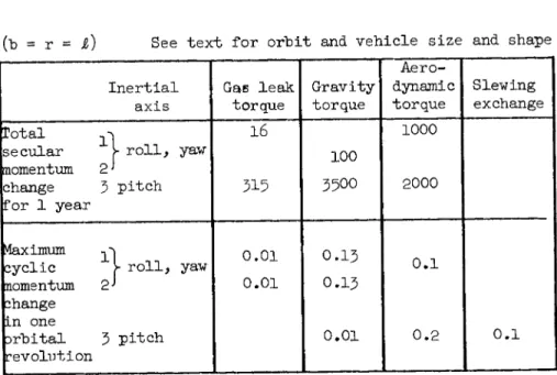
Table 3 Momentum change—illustrative example Units of Momentum Change: Newton-M-Sec
("b = r - i) See text for orbit and vehicle size and shape Inertial
axis
Gas leak torque
Gravity torque
Aero- dynamic torque
Slewing exchange Total ^
secular V roll, yaw momentum 2 '
change 3 pitch for 1 year
16
315
100 3500
1000
2000
Maximum
cyclic |- roll, yaw nomentum 2 J
change in one
Drbital 3 pitch revolution
0.01 0.01
0 . 1 3 0 . 1 3
0.01
0 . 1
0.2 0 . 1
Fig. 1 Local and inertial coordinates
Fig. 2 Aerodynamic torque on a satellite, showing.frontal area and moment arm
T R U E A N O M A L Y , A ( D E G R E E S ) —'
Fig. I4 Comparison of approximate integrand variations
Fig# 5 Slewing momentum exchange requirements for vertical satellites (b = r = J, )
ECCENTRICITY, e —'
Fig, 6 Slewing torque (acceleration) requirements for vertical satellite (b = r = £ )
Fig. 7 Attitude small angle displacement from local vertical coordinate frame