Case study in system development - Notes
Lajos Kollár
Nóra Sterbinszky
Case study in system development - Notes
Lajos Kollár Nóra Sterbinszky Publication date 2014
Copyright © 2014 Kollár Lajos, Sterbinszky Nóra Copyright 2014
Table of Contents
1. Introduction ... 2
1. Software processes ... 2
1.1. Waterfall model ... 3
1.2. Incremental development ... 4
1.3. Reuse-oriented software engineering ... 6
1.4. Process activities ... 7
1.4.1. Specification ... 7
1.4.2. Design and implementation ... 8
1.4.3. Validation ... 9
1.4.4. Evolution ... 9
2. UML ... 9
2.1. UML and metamodeling ... 11
2.2. Classification of UML 2.x diagrams ... 12
2.2.1. Structural diagrams ... 13
2.2.2. Behavioral diagrams ... 13
2.2.3. Common elements of UML diagrams ... 14
2.3. When to use UML diagrams? ... 15
2. Requirements engineering ... 16
1. Classification of requirements ... 18
2. The Software Requirements Specification document ... 20
2.1. When is an SRS said to be good? ... 21
2.2. Parts of an SRS ... 24
3. Gathering the requirements of the case study ... 25
4. Analysis ... 33
4.1. Customer use cases ... 39
4.1.1. Browse/search ... 39
4.1.2. Manage bookshelf ... 41
4.1.3. Move items to cart ... 42
4.1.4. Manage Shopping Cart ... 43
4.1.5. Move items to shelf ... 44
4.1.6. Place Order ... 45
4.1.7. Feed Back ... 46
4.1.8. Visit forums ... 47
4.2. Administrator use cases ... 48
4.2.1. Manage Products ... 49
4.2.2. Update Order Status ... 51
4.2.3. Process Feedback ... 52
4.2.4. Compose/Send Newsletter ... 52
4.2.5. Moderate Forums ... 53
4.3. Manager use cases ... 54
4.3.1. Set Action Offers ... 55
4.3.2. Set Customer Discounts ... 56
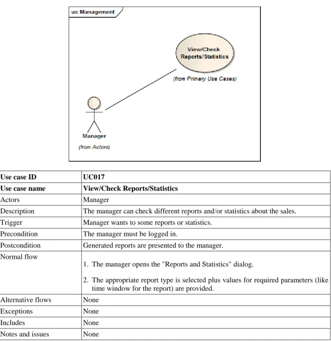
4.3.3. View/Check Reports/Statistics ... 56
4.4. Non-functional requirements ... 63
3. System modeling ... 65
1. Context models ... 66
2. Interaction models ... 67
3. Structural models ... 72
3.1. Identification of domain classes ... 85
3.2. Refining the model ... 88
4. Behavioral models ... 90
4.1. Data-driven modeling ... 90
4.2. Event-driven modeling ... 92
5. Robustness analysis ... 94
4. Architectural design ... 100
1. Architecture of the case study application ... 101
1.1. Logical architecture ... 101
1.2. Physical architecture ... 106
5. Detailed design ... 109
1. Criteria for modularization ... 109
1.1. Coupling ... 109
1.2. Cohesion ... 110
1.3. Open-Closed principle ... 111
2. Refinement and transformation of analysis-level design ... 111
2.1. Overview of attributes and methods ... 112
2.2. Shopping cart issues ... 116
2.3. What about Catalog? ... 117
2.4. Decouple OrderManagement from external dependencies ... 122
2.5. The show must go on ... 122
6. Using UML profiles ... 123
1. Profile ... 123
2. Metaclass ... 124
3. Stereotype ... 125
3.1. Stereotype application ... 126
3.2. Stereotype relationships ... 127
4. Tag definition ... 128
4.1. Tagged value ... 128
5. Extension ... 129
6. Reference ... 131
7. Profile application ... 131
8. UML profile diagram example ... 132
7. Service-oriented architecture ... 134
1. SoaML UML profile ... 134
2. Applying the SoaML profile using composite structure diagram of UML ... 136
References ... 140
List of Figures
1.1. Waterfall model [SOMMERVILLE2010] ... 3
1.2. Icremental development [SOMMERVILLE2010] ... 5
1.3. Reuse-oriented development [SOMMERVILLE2010] ... 6
1.4. Requirements engineering process [SOMMERVILLE2010] ... 7
1.5. Design process [SOMMERVILLE2010] ... 8
1.6. Layered architecture of MOF . ... 11
1.7. UML diagram types . ... 12
1.8. Framed class diagram with frame heading of long kind ... 15
2.1. Readers of different types of requirements specification [SOMMERVILLE2010] ... 18
2.2. Types of non-functional requirements [SOMMERVILLE2010] ... 20
2.3. Users of a requirements document [SOMMERVILLE2010] ... 21
2.4. Recommended structure for SRS documents ... 24
2.5. Actor Customer ... 30
2.6. Generalization relationship between actors ... 30
2.7. Use case example ... 31
2.8. An «extend» relationship between use cases. ... 31
2.9. Sample usage of extension points. ... 32
2.10. Use cases B and C are extracted from larger use case A into separate use cases ([UML- DIAGRAMS.ORG]). ... 32
2.11. Use case C is extracted from use cases A and B to be reused by both use cases using UML include relationship ([UML-DIAGRAMS.ORG]). ... 32
2.12. A use case including several use cases. ... 33
2.13. Overview of use case packages. ... 36
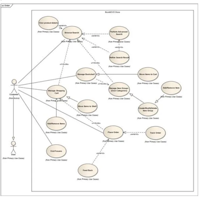
2.14. All identified use cases on a single diagram. ... 37
2.15. Overview of customer use cases. ... 39
2.16. Use case UC001 ... 39
2.17. Use case UC002 ... 41
2.18. Use case UC003 ... 42
2.19. Use case UC004 ... 43
2.20. Use case UC005 ... 44
2.21. Use case UC006 ... 45
2.22. Use case UC007 ... 46
2.23. Use case UC008 ... 47
2.24. Overview of administrator use cases. ... 48
2.25. Use case UC009 ... 49
2.26. Use case UC011 ... 51
2.27. Use case UC012 ... 52
2.28. Use case UC013 ... 53
2.29. Use case UC014 ... 53
2.30. Overview of manager use cases. ... 54
2.31. Use case UC015 ... 55
2.32. Use case UC016 ... 56
2.33. Use case UC017 ... 56
2.34. Activity diagram for use cases Browse/Search and Purchase Order ... 57
2.35. Activity diagram sample with lot of features ([SPARXSYSTEMS.COM]) ... 58
2.36. Sequence diagram of the activity Checkout ... 59
2.37. Call accept() if balance > 0, call reject() otherwise [UML-DIAGRAMS.ORG] ... 62
2.38. Post comments if there were no errors [UML-DIAGRAMS.ORG] ... 62
2.39. Potentially infinite loop [UML-DIAGRAMS.ORG] ... 62
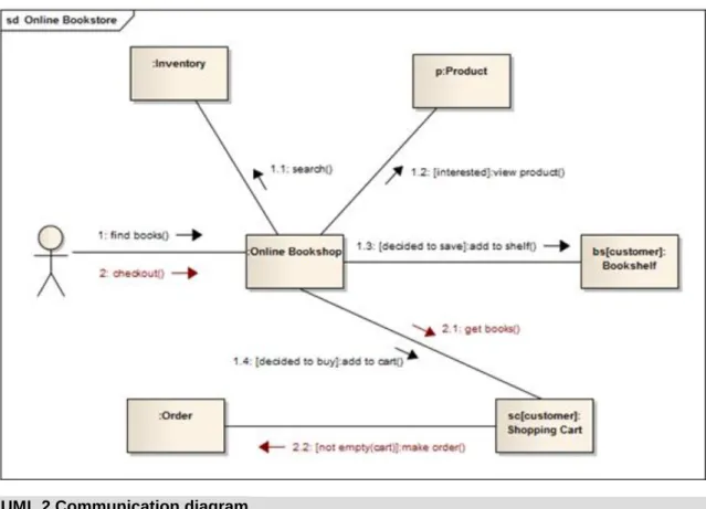
2.40. Web customer and Bookshop use (reference) interaction Checkout [UML-DIAGRAMS.ORG] 62 2.41. Communication diagram of the online bookstore's find book and checkout activities ... 63
3.1. Context model of the online store. ... 66
3.2. Use cases describing interactions to Bank and Shipping system (external systems). ... 67
3.3. Use cases describing interactions to Accounting system (external systems). ... 69
3.4. Use cases describing interactions to Accounting system (external systems). ... 70
3.5. Activity diagram of the use case Place Order and related activities ... 71
3.6. Class Customer—details suppressed ... 74
3.7. Class Customer—analysis level details. ... 74
3.8. Class Product is an abstract class ... 74
3.9. Math is utility class having static attributes and operations (underlined) ... 75
3.10. Interface Entity ... 76
3.11. Interface ProductDetails is realized (implemented) by Product. ... 77
3.12. Interface Product is used (required) by Order. ... 77
3.13. DateTime data type ... 78
3.14. Structured data type Address ... 78
3.15. Attributes of the Product contains an attribute of data type Money. ... 78
3.16. Primitive data type PersonalName. ... 78
3.17. Enumeration CurrencyType. ... 79
3.18. Attributes of the Product class are Name, Description and UnitPrice ... 79
3.19. Attribute multiplicities ... 80
3.20. Association relationship overview diagram [UML-DIAGRAMS.ORG] ... 81
3.21. Association between Customer and Order with association ends is placed by and places. ... 81
3.22. Both ends of association have unspecified navigability [UML-DIAGRAMS.ORG] ... 82
3.23. A2 has unspecified navigability while B2 is navigable from A2 [UML-DIAGRAMS.ORG] 82
3.24. A3 is not navigable from B3 while B3 has unspecified navigability [UML-DIAGRAMS.ORG] 82 3.25. A4 is not navigable from B4 while B4 is navigable from A4 [UML-DIAGRAMS.ORG] ... 82
3.26. A5 is navigable from B5 and B5 is navigable from A5 [UML-DIAGRAMS.ORG] ... 82
3.27. A6 is not navigable from B6 and B6 is not navigable from A6 [UML-DIAGRAMS.ORG] .. 82
3.28. Search Service has a Query Builder using shared aggregation ... 83
3.29. Composition example: Order is composed of OrderItems ... 83
3.30. Association class ProductSelection with details suppressed ... 84
3.31. Anonymous instance of the Customer class. ... 84
3.32. Instance book of the Book class has slots with values specified. ... 84
3.33. An object diagram that shows runtime instances of some classes ... 85
3.34. Initial domain classes ... 86
3.35. Product is part of ShoppingCart ... 87
3.36. Initial domain model ... 88
3.37. Revised domain model with supporting data types ... 89
3.38. Domain model after introducing Bookshelf ... 89
3.39. State machine diagram of the class ShoppingCart ... 93
3.40. State machine Order ... 94
3.41. Elements of a robustness diagram ... 95
3.42. Robustness diagram for Search product ... 95
3.43. Robustness diagram for Place order ... 96
3.44. Sequence diagram with bookshelf ... 98
3.45. Sequence diagram without bookshelf ... 99
4.1. Overall MVC-based architecture ... 102
4.2. Architecture described using a package diagram ... 103
4.3. Architecture described using a package diagram, revised ... 104
4.4. Interface ProductDetails is provided by Product. ... 105
4.5. Interface Product is used (required) by Order. ... 105
4.6. Delegation connector from the delegating port to the simple port of SearchEngine ... 106
4.7. Assembly connector between simple ports of Customer and Shipper and Shipper and Scheduler components ... 106
4.8. Component UserService realized by both UserServlet and UserDAO ... 106
4.9. Deployment diagram ... 107
5.1. Domain model ... 111
5.2. First version of our design model ... 113
5.3. Second version of our design model ... 116
5.4. Sequence diagram of order creation ... 116
5.5. Data Access Object ... 118
5.6. Data Access Object sequence diagram ... 119
5.7. DAO with abstract factory ... 119
5.8. DAO with abstract factory sequence diagram ... 120
5.9. Interface ProductDAO ... 121
6.1. Profile EJB [UML-DIAGRAMS.ORG] ... 123
6.2. Profile Servers [UML-DIAGRAMS.ORG] ... 124
6.3. EJB Profile shown as a package with URI attribute [UML-DIAGRAMS.ORG] ... 124
6.4. Metaclass Component [UML-DIAGRAMS.ORG] ... 125
6.5. Stereotype Computer extends metaclass Device [UML-DIAGRAMS.ORG] ... 125
6.6. Servlet Stereotype extends Component [UML-DIAGRAMS.ORG] ... 125
6.7. Stereotype Servlet with attached custom icon [UML-DIAGRAMS.ORG] ... 125
6.8. Actor is extended by stereotype Web Client with attached custom icon [UML-DIAGRAMS.ORG] 125 6.9. Device extended by Server stereotype with tag definitions and custom icon [UML- DIAGRAMS.ORG] ... 126
6.10. Stereotype «Servlet» applied to the model element SearchServlet [UML-DIAGRAMS.ORG] 126 6.11. Servlet stereotype applied to the class SearchServlet [UML-DIAGRAMS.ORG] ... 127
6.12. Servlet stereotype applied to the class SearchServlet [UML-DIAGRAMS.ORG] ... 127
6.13. «Web Client» stereotype applied to the Geek actor [UML-DIAGRAMS.ORG] ... 127
6.14. Computer stereotype with tags applied to class [UML-DIAGRAMS.ORG] ... 127
6.15. Abstract stereotype Session EJB is specialized by stereotypes Stateless EJB and Stateful EJB [UML- DIAGRAMS.ORG] ... 128
6.16. Stereotype Computer with tag definitions for vendor, CPU, and memory [UML-DIAGRAMS.ORG] ... 128
6.17. Stereotype Computer applied using "traditional" tag values notation [UML-DIAGRAMS.ORG] 129 6.18. Stereotype Computer applied with tag values in compartment [UML-DIAGRAMS.ORG] . 129 6.19. Stereotype Computer applied with tag values in comment note [UML-DIAGRAMS.ORG] 129 6.20. Metaclass Class is extended by stereotype Customer [UML-DIAGRAMS.ORG] ... 130
6.21. Required extension of metaclass Component by stereotype WebService [UML-DIAGRAMS.ORG] 130 6.22. Stereotype Provider extends either (or both?) Interface or Class metaclasses [UML- DIAGRAMS.ORG] ... 130
6.23. Metaclass Component is referenced (imported) by profile Servlets [UML-DIAGRAMS.ORG] 131 6.24. Profiles Java and Servlets applied to package WebApplication [UML-DIAGRAMS.ORG] 132 6.25. Simplified example of the unofficial Java EJB 3.0 Profile [UML-DIAGRAMS.ORG] ... 132
7.1. SoaML UML Profile - Contracts ... 135
7.2. SoaML UML Profile - Services ... 135
7.3. SoaML UML Profile - Service Data ... 136
7.4. Shipping service with two customers ... 137
7.5. ShippingService service interface ... 137
7.6. Service interfaces of a compound service ... 139
7.7. MessageTypes in purchase order processing ... 139
List of Tables
1.1. UML elements that can have frames ... 14
3.1. UML interpretations of classes ... 73
3.2. Multiplicity examples ... 80
3.3. Optional modifiers for properties ... 80
3.4. States of a shopping cart ... 93
3.5. Stimuli of a shopping cart ... 94
5.1. Class Order ... 113
5.2. Class Manager ... 114
List of Examples
2.1. Non-functional requirements for the case study. ... 63
Colophon
Chapter 1. Introduction
This case study is intended to serve as a study material for the course Technology of System Development for Software IT BSc students at the Faculty of Informatics, Unversity of Debrecen. The primary goal of the case study is to show the major steps of analysis and design activities of the software engineering lifecycle. The reader is expected to know the basics of the object-oriented (OO) paradigm and have some experience in programming in at least one OO language. However, the case study is intended to be independent of any concrete programming languages since it is out of the scope of this study material to deal with implementation details.
Knowledge about some guidelines, principles and patterns of software design might also be required. Students learn those pieces of background information in the prerequisite course.
Our running example will be a Book and DVD store. This example was chosen in order to be general enough for showing the most challenges that the specification and design of information systems have. The main purpose of the system is to allow the customers to browse and search products in an online warehouse, and they should also be able to place orders for those products. Detailed requirements will be discussed later, in the chapter entitled Requirements engineering.
The artifacts that are produced throughout the stages of development are documentations that are illustrated by models. Due to the rigid nature of some development documentations (i.e., requirements specification document or software design document) we will not include those documentations in their full details; instead, our focus is on the process of establishing the models describing the system of the case study. The models will predominantly be described using the Unified Modeling Language (UML) standard which is not only a de facto standard for describing models of software systems but has also become a de iure standard under reference numbers ISO/IEC 19505-1 and 19505-2. The current version of UML by the time of writing is 2.4.1 therefore we will use this version, however, version 2.5—which will have a major change in the organization of the specification—is under development.
This document is organized as follows. The rest of this chapter provides a very short overview of software process models and an outline of the UML 2.4.1 standard. Chapter 2 discusses the major issues of requirements engineering and provides a detailed view of the requirements of our case study. Chapter 3 introduces few high- level system modeling steps that will guide the reader to the architectural and detailed design covered in Chapter 4 and 5. The built-in extensibility mechanism of UML (called profiles) are detailed in Chapter 6 along with some examples of tailoring the design of the system to specific platforms. The last chapter is concerned with the emerging field of service-oriented architectures and discusses issues on how to expose system functionalities as services that can later be orchastrated into more complex services thus providing means of cross-organizational integration of software services.
1. Software processes
A software process can be defined as a set of related activities that will lead to the creation a software product.
Some systems are developed from scratch while other systems are developed based on existing systems by extending them. Another group of systems are created when existing components are integrated and configured.
According to [SOMMERVILLE2010], the four fundamental activities of software engineering are:
1. Software specification. Software's functionality, required product attributes and operational constraints are defined.
2. Software design and implementation. The software is designed and programmed in order to meet the specification.
3. Software validation. Software must be validated to ensure that it delivers the required functionalities, meets the required product attributes and fulfills the constraints that users (customers) want so briefly it is checking whether the system fulfills its goals.
4. Software evolution. The development of software is not finished with deployment but the system should evolve to meet the changing needs.
These are those processes that you will inevitably meet regardless of which software process is applied in your project. Of course, these processes are complex processes: they include sub-processes or sub-activities like requirements management, architectural design, interface design, unit testing, acceptance testing, etc. Some supporting activities like configuration management or documantation is also needed when creating software.
When describing software processes, the activities involved in those processes should be discussed like designing the user interface or specifying a data structure. Ordering of activities are also important from process view so we can refine our previous definition on software processes that will include not only the set of activities that should be executed during development but the ordering of those activities are important, as well.
Software process descriptions, however, are not limited to describe activities and ordering of them but they might also include information on
1. products or artifacts that are the results of a process activity,
2. roles that reflect the responsibilities of the people involved in the process, and
3. pre- and postconditions which define logical statements that must be true before or after a process activity has been performed or an artifact has been created.
A Software Requirements Specification document is an example of an artifact that is the result of the specification activity; programmer or project manager are examples of roles; while a precondition of integration testing might be that all the components that should be integrated are accessible and they are unit tested individually.
Important
Software processes are complex and, like all intellectual and creative processes, rely on people making decisions and judgments. There is no silver bullet that means that there is not an ideal process of developing software. Processes vary based on their domain, application type, devloping organization, etc. Majority of organizations have developed their own software development processes that are standardized at an organizational level. Processes have evolved to get the best out of the people's capabilities within an organization and the specific characteristics of the systems to be developed.
Sommerville describes three categories of software process models (that can be, however, often used together).
In fact, these are generic models that are not definitive descriptions of processes but are seen as abstractions. So you can think of them like software process frameworks that can and should be extended and/or adapted in order to create specific software engineering processes. These generic processes are:
1. Waterfall model which takes the four fundamental process activities described above and represents them as separate stages like requirements specification, software design, implementation, testing, and so on.
2. Incremental development which interleaves specification, development, and validation activities. The system is developed as a series of versions (increments), with each version adding functionality to the previous one.
3. Reuse-oriented development which is, instead of creating systems from scratch, focuses on the integration of existing components into a system so this is based on the existence of a significant number of reusable components.
Software processes can be categorized as either plan-driven or agile processes. Plan-driven processes are processes where all of the process activities are planned in advance and progress is measured against this plan while in agile processes, planning is incremental and it is easier to change the process to reflect changing customer requirements.
1.1. Waterfall model
The waterfall model is an example of a plan-driven process—in principle, you must plan and schedule all of the process activities before starting work on them. As it is seen on the figure, phases are cascaded from one phase to another, that is while it is known as the ‗waterfall model‘.
Figure 1.1. Waterfall model [SOMMERVILLE2010]
The principal stages of the waterfall model directly reflect the fundamental development activities:
1. Requirements analysis and definition. The system‘s services, constraints, and goals are established by consultation with system users. They are then defined in detail and serve as a system specification.
2. System and software design. The systems design process allocates the requirements to either hardware or software systems by establishing an overall system architecture. Software design involves identifying and describing the fundamental software system abstractions and their relationships.
3. Implementation and unit testing. During this stage, the software design is realized as a set of programs or program units. Unit testing involves verifying that each unit meets its specification.
4. Integration and system testing. The individual program units or programs are integrated and tested as a complete system to ensure that the software requirements have been met. After testing, the software system is delivered to the customer.
5. Operation and maintenance. Normally (although not necessarily), this is the longest life cycle phase. The system is installed and put into practical use. Maintenance involves correcting errors which were not discovered in earlier stages of the life cycle, improving the implementation of system units and enhancing the system‘s services as new requirements are discovered.
At least in principle, the result (artifact) of each phase is one or more documents that should be approved and the subsequent phase should not be started until the previous phase has completely been finished. In practice, however, these stages overlap and feed information to each other. During design, problems with requirements can be identified, during coding some of the design problems can be found, etc. The software process therefore is not a simple linear model but involves feedback from one phase to another as it is depicted on the figure.
Documents produced in each phase may then have to be modified to reflect the changes made.
In principle, the waterfall model should only be applied when requirements are well understood and unlikely to change radically during development as this model has a relatively rigid structure which makes it relatively hard to accomodate change when the process in underway.
An important variant of the waterfall model is formal system development, where the specification is described using a mathematical model which will later be refined into executable code (possibly through a series of other models) using consistency-preserving mathematical transformations. If the mathematical transformations applied are correct, we have a strong argument that a program generated in this way is consistent with its specification.
1.2. Incremental development
Incremental development is based on the idea of developing an initial implementation, exposing this to user feedback and evolving it through several versions until an acceptable system has been developed. Activities of specification, development and validation are not separated but interleaved. There are also lots of feedback across those activities.
Figure 1.2. Icremental development [SOMMERVILLE2010]
Incremental software development, which is a fundamental part of agile approaches, is better than a waterfall approach for most business, e-commerce, and personal systems. Incremental development reflects the way that we solve problems. We rarely work out a complete problem solution in advance but move toward a solution in a series of steps, backtracking when we realize that we have made a mistake. By developing the software incrementally, it is cheaper and easier to make changes in the software as it is being developed [SOMMERVILLE2010].
Each system increment captures a piece of the functionality that is needed by the customer. Generally, the early increments of the system should include the most important or most urgently required functionality. If this is the case then customers can evaluate the system at a relatively early stage in the development to see if it delivers what is required. If not, then only the current increment has to be changed and, possibly, new functionality defined for later increments. Compared to the waterfall model, incremental development has three important benefits:
1. There is a reduced cost of dealing with changing requirements since the amount of analysis and documentation activities that has to be redone is much less than is required when using the waterfall model.
2. It is much easier to get customer feedback on the work done. In waterfall-like processes (at least, theoretically) customers first meet the system when it is fully developed and tested and is deployed. If something is not acceptable than it is a real problem (that is the reason why waterfall should only be applied when requirements are well-understood). In iterative development, customers regularly receive a (not fully functional) version of the system that can be commented which provides valueable feedback.
3. More rapid delivery and deployment is possible so customers can get value out of the software earlier than is possible with the waterfall process. In incremental development it is allowed (and advised) to deliver useful functionalities even in early stages of the development.
Incremental development in some form is now the most common approach for the development of application systems. This approach can be either plan-driven, agile, or, more usually, a mixture of these approaches. In a plan-driven approach, the system increments are identified in advance; if an agile approach is adopted, only the early increments are identified but the development of later increments depends on progress and customer priorities.
1.3. Reuse-oriented software engineering
Reuse is one of the most important concepts of today's software engineering since it can not only save a given amount of work when existing components providing a given funtionality are reused but existing components might have lots of testing received so far so we can possibly build more reliable systems based on them.
Nowadays more and more software projects apply reuse to some extent, however, some of them relies more on reused components than others.
Reuse often happens in an informal way when people working on the project know of designs or code that are similar to what is required. They look for these, modify them as needed, and incorporate them into their system.
This is basically the application of patterns in the development process.
Figure 1.3. Reuse-oriented development [SOMMERVILLE2010]
A general process model for reuse-oriented software engineering is shown in the above figure. Although the initial requirements specification stage and the validation stage are comparable with other software processes, the intermediate stages in a reuse-oriented process are different. According to [SOMMERVILLE2010], these stages are:
1. Component analysis. Based on the requirements specification, components that implement (some part of) the specification are looked for. In the most of the cases there is no exact match and the components that may be used only provide some of the functionality required.
2. Requirements modification. During this stage, the requirements are analyzed using information about the components that have been discovered. They are then modified to reflect the available components. Where modifications are impossible, the component analysis activity may be re-entered to search for alternative solutions.
3. System design with reuse. During this phase, the framework of the system is designed or an existing framework is reused. The architects will perform the design by taking into account the components that are reused and they will organize the framework accordingly. New pieces of software may have to be designed if reusable components are not available.
4. Development and integration. Software that cannot be externally procured is developed, and the components and commercial-off-the-shelf (COTS) systems are integrated to create the new system. System integration, in this model, may be part of the development process rather than a separate activity.
There are basically three types of software components that can be used in a reuse-oriented process:
1. Web services that are developed according to well-known service standards and which will become available for remote invocation.
2. Collections of objects that are developed as a package to be integrated with a component framework such like .NET or Java EE.
3. Standalone software systems that are configured for use in a particular environment.
One of the most important advabtage of reuse-oriented software engineering is the reduced amount of software to be developed and therefore reduced cost and risks. As a consequence, it can also lead to faster delivery.
However, compromises must be achieved on requirements which might lead to a system that does not meet the real needs of users. Some control over the system evolution might also be lost as new versions of the reusable
components are not under the control of the organization using them (no influence on what functionalities to include/exclude, etc.).
1.4. Process activities
In this section some of the most important activities and sub-activities of the four general process activities will be discussed very briefly. For a more detailed description of activities, the reader should read some general software engineering textbooks like [SOMMERVILLE2010].
The four basic process activities of specification, development, validation, and evolution are organized differently in different development processes. In the waterfall model, they are organized in sequence while in incremental development they are interleaved. How these activities are performed might depend on the type of software, people involved in development, etc.
1.4.1. Specification
Software specification or requirements engineering is the process of understanding and defining what services are required from the system and identifying the constraints on the system‘s operation and development [SOMMERVILLE2010].
Figure 1.4. Requirements engineering process [SOMMERVILLE2010]
There are four main sub-activities in requirements engineering processes:
1. Feasibility study when an estimation of whether the identified requirements may be satisfied using current software and hardware technologies is made. A feasibility study should be relatively cheap and quick; it should inform the decision of whether or not to go ahead with a more detailed analysis.
2. Requirements elicitation and analysis, which is the process of deriving the system requirements through observation of existing systems, discussions with stakeholders, etc. This may involve the development of one or more system models and prototypes that can help us understanding the system to be specified.
3. Requirements specification, which is the activity of translating the information gathered during the analysis activity into a (formal or informal, depending on the underlying process used) document that defines a set of requirements. Two types of requirements may be included in this document:
a. User requirements are abstract statements of the system requirements for the customer and end-user of the system;
b. System requirements are a more detailed description of the functionality to be provided.
4. Requirements validation is the process of checking the requirements for realism, consistency and completeness. During this process our goal is to reveal errors in the requirements document. When an error is found, the requirements specification document needs to be modified to correct the problems.
Of course, the activities in the requirements process are not necessarily executed in a strict sequence but the activities of analysis, definition, and specification can be interleaved. In agile methods, such as extreme programming, requirements are developed incrementally according to user priorities and the elicitation of requirements comes from users who are part of the development team.
1.4.2. Design and implementation
The implementation phase is the process of converting a system specification into an executable system. It always involves processes of software design and programming but, if an incremental approach to development is used, may also involve refinement of the software specification [SOMMERVILLE2010].
Figure 1.5. Design process [SOMMERVILLE2010]
The activities needs to be carried out during the design process vary depending on the type of the system needs to be developed. However, for the development of information systems, the main four activities are the following:
1. Architectural design, where the overall system structure is identified. It involves finding principal components (sometimes called sub-systems or modules) along with their relationships. Distribuution of components (to hardware nodes and to development teams) should also be discussed.
2. Interface design, where the interfaces among various system components are defined. This interface specification must be unambiguous. With a precise interface, a component can be used without other components having to know how it is implemented. Once interface specifications are agreed, the components can be designed and developed concurrently.
3. Component design, where we take each system component and design how it will operate. This may be a simple statement of the expected functionality to be implemented, with the specific design left to the programmer.
4. Database design, where the data structures used by the system are designed and their representation in a database is dealt with. The sub-activities that need to be performed here depends on whether an existing database is to be reused or a new database is to be created.
1.4.3. Validation
Software validation or, more generally, verification and validation (V&V) is intended to show that a system both conforms to its specification and that it meets the real needs of the customer or user of the application.
Testing, where the system is executed using simulated test data, is an important validation technique but some checking processes, such like inspections or reviews should also be applied during V&V processes.
Testing has three main stages [SOMMERVILLE2010]:
1. Development testing. The components that compose the system are tested by the people developing the system. Each component is tested independently, without other system components. Components may be simple entities such as functions or object classes, or may be coherent groupings of these entities. Test automation tools, such as JUnit are commonly used.
2. System testing. System components are integrated to create a complete system. This process is concerned with finding errors that result from unanticipated interactions between components and component interface problems. It is also concerned with showing that the system meets its functional and non-functional requirements, and testing the emergent system properties.
3. Acceptance testing. This is the final stage in the testing process before the system is accepted for operational use. The system is tested with data supplied by the system customer rather than with simulated test data.
Acceptance testing may reveal errors and omissions in the system requirements definition, because the real data exercise the system in different ways from the test data.
1.4.4. Evolution
Requirements are always changing, even after the system has been put into its operating environment. Emerging systems with new interfaces that our software needs to communicate with, or business environment changes might result in changing needs.
Historically, there has always been a split between the process of software development and the process of software evolution (software maintenance). However, this distinction between development and maintenance is increasingly irrelevant. Hardly any software systems are completely new systems and it makes much more sense to see development and maintenance as a continuum. Rather than two separate processes, it is more realistic to think of software engineering as an evolutionary process where software is continually changed over its lifetime in response to changing requirements and customer needs [SOMMERVILLE2010].
2. UML
The Unified Modeling Language™ (UML®) is a standard visual modeling language intended to be used for
• modeling business and similar processes,
• analysis, design, and implementation of software-based systems.
UML is a common language used by various parties involved in the software engineering lifecycle: business analysts, software architects, developers, testers and system administrators. It is used to describe, specify, design, and document existing or new business processes, structure and behavior of artifacts of software systems.
UML can be applied to various application domains (e.g., banking, selling and buying product via internet, healthcare, finance, etc.) and it can be used together with all major object and component software development methods and for diverse implementation platforms (e.g., Java EE, .NET).
It is important to emphasize that UML is ―only‖ a standard modeling language, not a software development process. A software development process is expected to
• provide guidance to the order of the activities performed by a group of people (the development team),
• specify what artifacts should be developed,
• control the tasks performed by both individual developers and the team as a whole, and
• offer criteria in order to monitor and measure the produced artifacts and the performed activities within a project.
UML is not about providing these pieces of information. It is not prescriptive but descriptive: as a modeling language, it does not prescribe any activities and does not require to produce any artifacts; however, it can be used to describe the artifacts that an applied software development process requires.
Therefore, UML is intended to be process independent and it can be applied in the context of different processes. However, it is most suitable for use case-driven, iterative and incremental development processes. An example of such process is Rational Unified Process (RUP).
Important
Our case study does not depend on the application of a given software process model. However, the presentation of the steps will resemble the reader similar to those of plan-driven approaches. The reason for that is very trivial: plan-driven approaches are more documentation-oriented than agile methods (which are much more code-oriented) and therefore, in our opinion, it is easier to describe (and understand) a system in a plan-driven way for learning purposes, especially because we focus on the analysis and design instead of actual programming.
UML is not completely visual which means that given some UML diagram, the described part or behavior of the system might not be understood from the diagram alone. Some pieces of information could be intentionally omitted from the diagram, some information represented on the diagram could have different interpretations, and some concepts of UML have no graphical notation at all, so there is no way to depict those on diagrams.
• For example, semantics of multiplicity of actors and multiplicity of use cases on use case diagrams is not defined precisely in the UML specification and could mean either concurrent or successive usage of use cases.
• Name of an abstract classifier is shown in italics while final classifier has no specific graphical notation, so there is no way to determine whether classifier is final or not from the diagram.
This, on one hand, provides a great flexibility when having a more or less informal system description intended to be read by human beings (some people involved in the process). On the other hand, the lack of proper semantics (that can lead to ambigous interpretations) or missing notations are problematic when applying a model-driven style of development that would require precise statements about each models so that a model tarnsformation or code generation migh take place.
A UML diagram is a partial graphical representation (view) of a model of a system under design, implementation, or already in existence. UML diagrams contain graphical elements (symbols)—UML nodes connected with edges (also known as paths or flows)—that represent elements in the UML model of the designed system. Since it is uncommon to describe a system by using UML models only, system description might also contain other documentation such as use cases written as templated texts.
The UML offers a set of diagram types to capture the different aspect of software systems. The diagram type is defined by the primary graphical symbols shown on the diagram. For example, a diagram where the primary symbols are classes is a class diagram. A diagram showing actors and use cases is called a use case diagram. A sequence diagram shows sequence of message exchanges between lifelines.UML specification also allows to create a mixture of different kinds of diagrams, e.g. to combine structural and behavioral elements to show a state machine nested inside a use case. Consequently, the boundaries between the various kinds of diagrams are not strictly enforced. At the same time, some UML tools do restrict set of available graphical elements which could be used when working on specific type of diagram.
2.1. UML and metamodeling
Object Management Group (OMG) is the name of the organization responsible for developing and maintaining the UML standard. UML version 2.4.1 consists of two separate documents, namely, the UML Infrastructure ([UML2.4.1INFRA]) and the UML Superstructure ([UML2.4.1SUPER]).
Note
This will be changed from the 2.5 version of the UML since these documents will be merged together.
UML Infrastructure defines a core metamodel that is used to define the full MetaObject Facility (MOF), UML and Profiles. The key concept to understand is that in UML, reuse is the pervasive design consideration. The core of the UML Infrastructure is defined on an abstract level, and is extended by using object-oriented principles to define the UML Superstructure. Superstructure complements Infrastructure by defining user level constructs required for UML 2.4.1 (e.g., various digram types).
Note
The MetaObject Facility (MOF) Specification is the foundation of OMG's industry-standard environment where models can be exported from one application, imported into another, transported across a network, stored in a repository and then retrieved, rendered into different formats (including XMI, OMG's XML-based standard format for model transmission and storage), transformed, and used to generate application code.
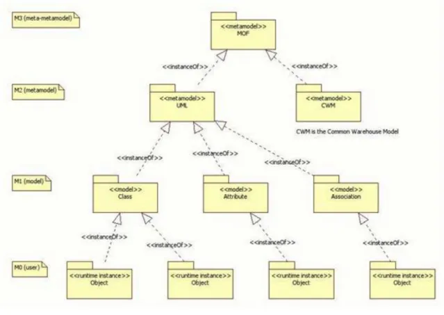
MOF is designed as a four-layered architecture (see Figure 1.6, ―Layered architecture of MOF .‖). It provides a meta-meta model at the top layer, called the M3 layer. This M3-model is the language used by MOF to build metamodels, called M2-models. The most prominent example of a Layer 2 MOF model is the UML metamodel, the model that describes the UML itself. These M2-models describe elements of the M1-layer, and thus M1- models. These would be, for example, models written in UML. The last layer is the M0-layer or data layer. It is used to describe real-world objects.
Beyond the M3-model, MOF describes the means to create and manipulate models and metamodels by defining CORBA interfaces that describe those operations. Because of the similarities between the MOF M3-model and UML structure models, MOF metamodels are usually modeled as UML class diagrams. A supporting standard of MOF is the XML Metadata Interchange (XMI), which provides an exchange format based on XML for models of the various layers.
MOF is a closed metamodeling architecture; it defines an M3-model, which conforms to itself. MOF allows a strict meta-modeling architecture; every model element on each layer is strictly in correspondence with a model element of the layer above. MOF only provides a means to define the structure, or abstract syntax of a language or of data. For defining metamodels, MOF plays exactly the role that EBNF plays for defining programming language grammars. MOF is a Domain Specific Language (DSL) used to define metamodels, just as EBNF is a DSL for defining grammars. Similarly to EBNF, MOF could be defined in MOF. This is referred to as metacircular description.
Figure 1.6. Layered architecture of MOF http://umlbase.com/learn/tag/meta-object-
facility/.
2.2. Classification of UML 2.x diagrams
UML specification defines two major kinds of UML diagrams: structural diagrams and behavioral diagrams.
Structural diagrams show the static structure of the system and its parts on different abstraction and implementation levels and how they are related to each other. The elements in a structure diagram represent the meaningful concepts of a system, and may include abstract, real world and implementation concepts.
Behavioral diagrams show the dynamic behavior of the objects in a system, which can be described as a series of changes to the system over time.
UML 2.4 diagrams could be categorized hierarchically as shown below:
Figure 1.7. UML diagram types http://creately.com/blog/diagrams/uml-diagram-types-
examples/.
2.2.1. Structural diagrams
Structural diagrams are not utilizing time related concepts, do not show the details of dynamic behavior.
However, they may show relationships to the behaviors of the classifiers exhibited in the structure diagrams.
• Class diagram is a static structure diagram which describes structure of a system at the level of classifiers (classes, interfaces, etc.). It shows some classifiers of the system, subsystem or component, different relationships between classifiers, their attributes and operations, constraints.
• Object diagram can be defined as "a graph of instances, including objects and data values. A static object diagram is an instance of a class diagram; it shows a particular snapshot of the detailed state of a system at a point in time." It also stated that object diagram is "a class diagram with objects and no classes."
• Package diagram shows packages and relationships between the packages. A package is a namespace that is used to group together elements that are semantically related and might change together. It is a general purpose mechanism to organize elements into groups to provide better structure for system model.
• Composite Structure Diagram could be used to show the internal structure of a classifier, classifier interactions with the environment through ports, a behavior of a collaboration. The term "structure" for this type of diagrams is defined in UML as a composition of interconnected elements, representing run-time instances collaborating over communications links to achieve some common objectives.
• Component diagram shows components and their dependencies. This diagrams type plays an important role in modeling systems that are used for Component-Based Development (CBD), to describe systems with Service-Oriented Architecture (SOA).
• Deployment diagram shows architecture of the system as deployment (distribution) of software artifacts to deployment targets. In UML 2.x, artifacts are deployed to nodes, and artifacts could manifest (implement) components so components are deployed to nodes indirectly through artifacts. Deployment diagrams could be used to show logical or physical network architecture of the system.
• Profile diagram is an auxiliary UML diagram which allows defining custom stereotypes, tagged values, and constraints. The Profile mechanism has been defined in UML for providing a lightweight extension mechanism to the UML standard. Profiles allow to adapt the UML metamodel for different platforms (such as Java EE or .NET), or domains (such as real-time or business process modeling). Even though the concept of profiles are older, Profile diagrams were first introduced in UML 2.0.
2.2.2. Behavioral diagrams
Behavioral diagrams show the dynamic behavior of the objects in a system, which can be described as a series of changes to the system over time.
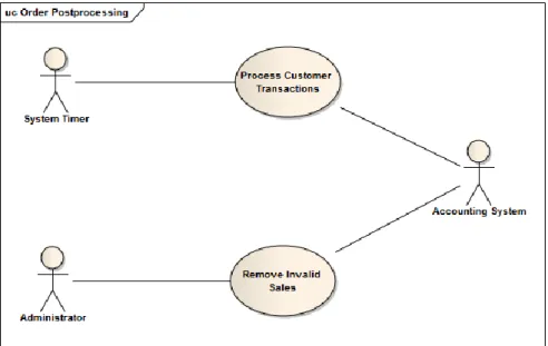
• Use case diagrams are behavior diagrams used to describe a set of actions (use cases) that some system or systems (subject) should or can perform in collaboration with one or more external users of the system (actors) to provide some observable and valuable results to the actors or other stakeholders of the system(s).
Note, that UML 2.4 specification also defines use case diagrams as specialization of class diagrams (which are structure diagrams). Use case diagrams could be considered as a special case of class diagrams where classifiers are restricted to be either actors or use cases and the most used relationship is association.
• Activity diagram shows sequence and conditions for coordinating lower-level behaviors, rather than which classifiers own those behaviors. These are commonly called control flow and object flow models.
• State machine diagram is used for modeling discrete behavior through finite state transitions. In addition to expressing the behavior of a part of the system, state machines can also be used to express the usage protocol of part of a system. These two kinds of state machines are referred to as behavioral state machines and protocol state machines.
• Interaction diagrams include few different types of diagrams:
• Sequence diagram is the most common kind of interaction diagrams, which focuses on the message interchange between lifelines (objects).
• Communication diagram (previously known as Collaboration Diagram) is a kind of interaction diagram, which focuses on the interaction between lifelines where the architecture of the internal structure and how this corresponds with the message passing is central. The sequencing of messages is given through a sequence numbering scheme.
• Interaction overview diagram defines interactions through a variant of activity diagrams in a way that promotes overview of the control flow. Interaction overview diagrams focus on the overview of the flow of control where the nodes are interactions or interaction uses. The lifelines and the messages do not appear at this overview level. Timing diagrams are used to show interactions when a primary purpose of the diagram is to reason about time.
• Timing diagrams are used to show interactions when a primary purpose of the diagram is to reason about time. They focus on conditions changing within and among lifelines along a linear time axis.
2.2.3. Common elements of UML diagrams
Each UML diagram has a contents area. As an option, some diagrams may also have a frame (shown as rectangle) with frame heading. The frame could be used in the cases when the diagrammed element has some owned elements that are attached to the border, like ports for classes and components, and entry/exit points on state machines.
The heading of a frame represents the kind, name, and parameters of the element owning or namespace enclosing the elements represented in the contents area.
frame-heading ::= [ element-kind ] element-name [ parameters ] element-kind ::= short-element-kind | long-element-kind
The following UML elements and namespaces could have frames:
Table 1.1. UML elements that can have frames
Short kind Long kind - owning element or enclosing namespace
act activity
class class
cmp component
dep deployment
sd interaction
pkg package
stm state machine
Short kind Long kind - owning element or enclosing namespace
uc use case
Figure 1.8. Framed class diagram with frame heading of long kind
Note
It is a common mistake to assume that frame kind specifies type of the depicted UML diagram. In fact, type of the diagram is defined by the primary graphical elements shown in the contents area of the diagram. Frame kind is kind of the UML element owning or namespace enclosing the elements shown in the frame contents area. For instance, an activity, sequence or state machine diagram belonging to a use case (i.e., providing more details on it) can still be of a use case type.
2.3. When to use UML diagrams?
UML diagrams are mostly useful if they express something in a higher level of abstraction than the code.
Writing UML just for the sake of writing UML becomes unneeded bureaucracy and makes the project and the code less adaptable to changes with no benefit whatsoever. For example, a UML class diagram showing all the classes on a package, with all their attributes and methods—something that can be easily auto-generated—
provides no value at all: it is at the same level of abstraction than the code. Plus, the code will most surely be a better source for that information because it will always be up to date, and it will probably be documented and organized in a way that is easier to know which methods/attributes/things are more important. On the other hand, if you have concepts of a higher level of abstraction than what can be expressed on the code, documenting those on a diagram is a good idea. For example, a diagram showing the higher level abstract modules on a complex system, with their dependencies and maybe a little description of their responsibilities and what package/namespace they map to in the source code can be a really useful for a new team member that needs to be introduced to the project, or can also be used to figure out where a new class/functionality should be thrown.
Another example of a useful diagram could be a sequence diagram showing the high-level steps to be taken in a communication protocol. Maybe each step of those have it's little quirks and complexities, but it is probably enough to describe them in the code itself. The higher level diagram can help a programmer to understand the
"big picture" of things easily without needing to worry about the complexities of each interaction. Anyway, those are just some examples; there are lots of cases where a simple diagram can be of a lot of help. Just remember that you should be doing them only when you cannot express something in the code itself. If you find yourself using UML diagrams to explain the source code itself, make the source code more self-documenting instead. Finally, some of the general rules that apply to code can also apply to diagrams: avoid repeating yourself, keep it simple, don't fear of changing things (just because something is documented on a UML diagram does not mean it cannot be changed) and always think of who will be reading/maintaining those diagrams in the future (probably your future-self) when writing them.
Important
It is not our goal to introduce the details of all diagram types of UML 2.x to the reader. It is the case study which drives which UML diagram types will be used: those that are needed to model our sample application. However, we will deal with the majority of diagram types (at a different level of detail), even if it is important to underline that not all diagram types are equally important. We use some of them much more frequently than others, that is the reason why particular importance will be given to Use case diagrams, Class diagrams and Sequence diagrams. Different application types might require the use of different diagram types.
Chapter 2. Requirements engineering
Requirements are the basis for every project, defining what the stakeholders—users, customers, suppliers, developers, businesses—in a potential new system need from it and also what the system must do in order to satisfy that need. To be well understood by everybody they are generally expressed in natural language and herein lies the challenge: to capture the need or problem completely and unambiguously without resorting to specialist jargon or conventions. Once communicated and agreed, requirements drive the project activity.
However, the needs of the stakeholders may be many and varied, and may indeed conflict. These needs may not be clearly defined at the start, may be constrained by factors outside their control or may be influenced by other goals which themselves change in the course of time. Without a relatively stable requirements base, a development project can only flounder. It is like setting off on a sea journey without any idea of the destination and with no navigation chart. Requirements provide both the ―navigation chart" and the means of steering towards the selected destination.
Agreed requirements provide the basis for planning the development of a system and accepting it on completion.
They are essential when sensible and informed tradeoffs have to be made and they are also vital when, as inevitably happens, changes are called for during the development process. How can the impact of a change be assessed without an adequately detailed model of the prior system? Otherwise, what is there to revert to if the change needs to be unwound? Even as the problem to be solved and potential solutions are defined we must assess the risks of failing to provide a satisfactory solution. Few sponsors or stakeholders will support product or systems development without a convincing risk management strategy. Requirements enable the management of risks from the earliest possible point in development. Risks raised against requirements can be tracked, their impact assessed and the effects of mitigation and fallback plans understood long before substantial development costs have been incurred.
Requirements therefore form the basis for:
• project planning;
• risk management;
• acceptance testing;
• tradeoff;
• change control.
The most common reasons for project failures are not technical. A report created by the Standish Group based on a survey identified that incomplete requirements and the lack of user involvement are primary reasons for project failures. Other reasons include lack of resources, unrealistic expectations, lack of executive support, changing requirements, lack of planning , etc. More than half of those reasons (even the most influential two) are directly related to requirements.
The problems fall into three main categories:
• Requirements—either poorly organized, poorly expressed, weakly related to stakeholders, changing too rapidly or unnecessary; unrealistic expectations.
• Management problems of resources—failure to have enough money, and lack of support or failure to impose proper discipline and planning; many of these arise from poor requirements control.
• Politics—which contributes to the first two problems.
All these factors can be addressed at fairly low cost.
Since requirements are interconnected with other aspects of systems engineering and project management, it is quite challenging to find a satisfactory scope for a definition of requirements engineering.
First of all, what is a requirement? IEEE Standard for Application and Management of the Systems Engineering Process (IEEE Std 1220-2005) gives the following definition:
Requirement: a statement that identifies a product or process operational, functional, or design characteristic or constraint, which is unambiguous, testable or measurable, and necessary for product or process acceptability (by consumers or internal quality assurance guidelines).
Let us take a short look on the elements of this definition:
• Statement. That a requirement should be a statement is perhaps biased towards textual description, while they can also be captured in tabular form or in diagrammatic form (especially when using such a modeling language like UML), in formal notations, or even in domain-specific notations. The important concept, though, is to have a set of traceable, manageable elements identified as requirements.
• Product or process. Complete solutions contain varying mixtures of product (things that are built in response to requirements) and process (procedures for using the things that are built). Requirements may therefore define process as well as product. In addition to this, there may be requirements that constrain the way how the product should be developed, usually for quality control purposes.
• Operational, functional, or design characteristic or constraint. There are many different kinds of requirement, giving rise to different kinds of language, analysis, modelling, process and solution. Note that this definition has carefully avoided the term ―non-functional", because there is a debate about what this actually means. Design characteristics cover performance, usability, safety, maintainability and a host of other qualities.
• Unambiguous. A statement of requirement has desirable qualities that will be addressed in detail later. In brief, a requirement should lend itself to a clear, single understanding, common to all parties involved.
• Testable or measurable. Requirements are used to test that the design or solution is acceptable. For this to be possible, the requirement should be quantified, thus providing a means of ―measuring" the solution against it.
• Necessary for product or process acceptability. Requirements play a multi-dimensional role: on one hand, they define what should be designed and developed, and, on the other hand, they also define how the solution should be tested and accepted. So they have an influence in the earliest stages of the development process as well as in the latest stages during acceptance.
• By consumers or internal quality assurance guidelines. Requirements come from many sources, including but not limited to customers, regulatory bodies, users and internal quality procedures.
Some other synonyms for requirements are: aims, aspiratins, capabilities, criteria, constraints, directives, doctrines, duties, expectations, features, functions, goals, missions, needs, obligations, objectives, orders, regulations, rules, etc.
The term ―stakeholder" has already been used without giving a definition:
Stakeholder: An individual, group of people, organisation or other entity that has a direct or indirect interest (or stake) in a system.
A stakeholder‘s interest in a system may arise from using the system, benefiting from the system (in terms of revenue or other advantage), being disadvantaged by the system (in terms, for instance, of cost or potential harm), being responsible for the system, or otherwise being affected by it. Stakeholders are legitimate sources of requirements.
According to [HULL2010], requirements engineering is the subset of systems engineering concerned with discovering, developing, tracing, analyzing, qualifying, communicating and managing requirements that define the system at successive levels of abstraction.
This definition lists carefully selected key activities that are considered proper to requirements engineering.
There are some activities closely related to requirements that are considered to be part of some other discipline.
An example of this is system testing or verification; while requirements should have the qualities needed to ensure that the solution can be verified, the verification activity itself is another discipline. It also references the concept of requirements existing at various levels of development. Here are some notes on the definition:
• Discovering. This covers a number of terms often used, such as requirements elicitation and capture.
![Figure 1.2. Icremental development [SOMMERVILLE2010]](https://thumb-eu.123doks.com/thumbv2/9dokorg/1109509.77332/15.892.123.765.207.567/figure-icremental-development-sommerville.webp)
![Figure 1.5. Design process [SOMMERVILLE2010]](https://thumb-eu.123doks.com/thumbv2/9dokorg/1109509.77332/18.892.125.770.368.889/figure-design-process-sommerville.webp)

![Figure 2.35. Activity diagram sample with lot of features ([SPARXSYSTEMS.COM])](https://thumb-eu.123doks.com/thumbv2/9dokorg/1109509.77332/68.892.129.768.107.439/figure-activity-diagram-sample-lot-features-sparxsystems-com.webp)