THE RHEOLOGY OF CONCRETE
1M. Reiner
I. Introduction 3 41
II. Fresh Cement paste 3 44
1. Structural Considerations 344
2. Rheological Properties 3 45
III. Set Cement 3 46
1. Structural Considerations 346
2. Unstressed Deformations 3 47
3. Rheological Properties 3 4^
IV. Mortar 3 51
1. Fresh Mortar 3 5*
2. Viscosity of Set Mortar 3 52
3. Elasticity of Set Mortar 3^4
V. Concrete 3 56
1. Fresh Concrete 3 56
2. Rheological Behavior of Set Concrete 3 58
3. Viscous Creep 3 61
VI. Reinforced Concrete 3 63
Nomenclature 3 64
I. Introduction
Concrete is a material consisting of mineral aggregates dispersed in a binder. If the binder is made of cement, one speaks of cement concrete or simply concrete. If it is lime, the term is lime concrete, and so on. The mineral aggregates are usually of two kinds, the fine aggregates called sand and the coarse aggregates which are either broken stone or gravel. In a good concrete both fine and coarse aggregates are well graded so as to give the greatest density. If all grades are present one speaks of "con- tinuous" grading; when a certain class of aggregates is missing in the mix, grading is "discontinuous." The usual designation of a concrete as, e.g., 1:2:4 means one part binder, two parts sand, and four parts stones,
1 For a more detailed treatment compare the chapters by E. Forslind, E. Torroja, and A. Paez, P. Mason, and A. M. Freudenthal, in "Elasticity and Inelasticity of Building Materials" (M. Reiner, ed.), pp. 64, 222, 253, 290. North-Holland, Amster- dam, 1954.
341
all measured separately by bulk volume, but cement is actually added in equivalent weight. The water-cement ratio (WC) is the ratio of water to cement by weight. Sometimes very fine aggregates are added directly to the binder: these are called fillers. The mixture of binder and sand is called mortar, and concrete can accordingly be regarded as a mixture of mortar and coarse aggregates. The mortar can be considered as a suspension of sand in the binder. Mortar and concrete will naturally possess voids or pores filled with air and, strictly speaking, air should be considered as one of their constituents.
Commercial cement is sold as a powder. There are two kinds of cement:
the natural cement and Portland cement. Natural cements were already used by the Romans. They are produced by calcining limestones associated with a considerable proportion of clay at temperatures usually within a range 1100 to 1300°C. These are then ground to obtain a fine powder. By far the most important cement, however, both technically and economically, is the modern Portland cement, invented in 1824. This differs from most of the natural cements in being an equilibrium product at the kiln tempera- tures. In the present chapter the term "cement" will always refer to Portland cement.
By the addition of water, cement is made into a concentrated suspension : the cement paste. Through the chemical setting process this is converted into "set2 cement," which is an artificial stone. The term "cement" is used indiscriminately for the powder, the paste and the stone but their rheological properties are naturally quite different.
The mixture of paste and sand is called fresh mortar: this is converted into "set" mortar. Similarly we have to distinguish between fresh and set concrete.
In order to understand the rheological behavior of concrete it is there- fore necessary to consider (a) the fresh cement paste, its setting, and the rheological behavior of the resulting set cement; similarly (6) the fresh cement mortar, its setting, and the rheological behavior of the resulting set mortar; and finally (c) the concrete itself under the same three aspects.
In a different arrangement four kinds of rheological problems can be distinguished: First there are those connected with the rheology of the constituent materials, mainly cement, but also water. Secondly there are the problems connected with the manufacture of the concrete, constituting the rheology of the plastic mix and dealing with such properties as "work- ability" and "segregation." Thirdly there are those connected with the finished product dealing with elasticity, permanent set, and creep. As concrete has great strength in compression but little in tension, it is re-
2 The term "set" is also in use in rheology with an entirely different meaning, com- pare Section V, 2 .
inforced by the insertion of steel rods. The problems specific to the aniso- tropic material reinforced concrete form the fourth group: they are dealt with in Section VI below.
The rheology of concrete started with investigations of its strength.
Strength, though the most complicated rheological property, was, as can easily be understood, the first to receive attention and it has remained the one with which the material-testing laboratories are most concerned. From 1845 on, the crushing strength and later tensile strength of cement, mortar and finally of concrete was determined. To date the principal rheological concrete tests which have been standardized in the United States and Britain are determinations of crushing (or compressive) strength, trans- verse (or bending) strength, and the loading test of concrete floors. Thus the traditional attitude of the average structural engineer to concrete is as if it belonged to the structural materials such as steel and wood not subject to a time factor. When it is felt that this approach is not consistent with facts, sometimes experiments are undertaken which imitate as much as possible the conditions under which the structural elements are required to act in the building structure and the investigator is satisfied with empiri- cal results for these different conditions which can very seldom be cor- related among themselves. This method of investigation has on occasion reached a very large scale, e.g., the model tests of the Committee on Arch Dam Investigations, Denver, Colorado, 1931. Since then small-scale rheological experiments have answered the questions raised more fully and certainly more economically.
It appears that the first systematic investigations which may be called rheological were made by Bach in the eighteen-nineties. Bach drew the conclusion that concrete does not obey Hooke's law of the proportionality of stress and strain and that this rule should be replaced by another law in which the strain is proportional to the nth power of the stress. This
"power law" is still in use, despite the serious theoretical objections to it.3 Bach was also the first to distinguish between the elastic, recoverable, and the permanent, nonrecoverable part of the deformation, but probably included delayed unrecovered strains in the latter. However, most experi- mental material collected before the property of creep in concrete was discovered is of little, if any, value. A new era started in the twenties, when McMillan4 in the United States reported upon observations of a column in compression which, at the end of a period of 600 days, showed a continuous deformation still proceeding at the average rate.
3 Compare M. Reiner, Naturwissenschaften 21, 294 (1933), but there is no objection to the use of the Nutting-Scott Blair equation as an interpolation formula. Cf. also G. W. Scott Blair and M. Reiner, Appl. Sei. Research A2, 225-234 (1950).
4 F. R. McMillan, Proc. Am. Concrete Inst. 17, 150 (1921).
II. Fresh Cement Paste
1. STRUCTURAL CONSIDERATIONS
The cement paste is formed by mechanically admixing water to the cement powder. The water wets the cement granules, which then form
more or less compact agglomerations as is evident under the microscope.
As the tendency of a physical system to reduce its interfacial surface is a spontaneous thermodynamic process, it is possible, for example, that certain points of two solid particles can produce a direct bond between them, to the extent of forming part of the same crystalline pattern. This has been revealed by the electron microscope, at least during the early stages of the growing crystalline nuclei. Such a process may be brought about by substances from the solution or by the movement of the inter- vening liquid or adsorbed film, considering the greater energy of the particles situated along the edges or sharp convexities of the lattice al- ready formed.
Forslind1 has expounded different views. Regarding the water itself, he points to the fact that the association of the water molecules, which is governed by the hydrogen bond, produces a definite structural arrange- ment. There results a three-dimensional lattice in ice which is retained above the melting point. At the melting point there takes place a transi- tion from the ice lattice to the water lattice. Thermal vibrations may cause a water molecule to leave its regular lattice point, thus causing a
"Frenkel defect." The molecule enters into the interstices of the structure, a process which decreases the over-all thermal expansion of the molecular system and causes the increase of the density of ice to that of water when a thermal equilibrium is attained. The equilibrium is disturbed under the influence of a deformation applied to the system until a new steady state is reached at constant rate of deformation. Intermolecular potential barriers in the crystalline phase prevent all but the largest thermal ampli- tude fluctuations from contributing to defect formation and thus to flow.
The potential barriers are depressed with increase of strain until a yield point is reached. According to this view, aqueous systems therefore possess both a yield point and structural viscosity, and water may thus be regarded as essentially crystalline. When the cement powder is mixed with water a hydrogel is produced. The water molecules are adsorbed on a solid sub- strate and it may be supposed that the spatial arrangement of the first adsorbed layer corresponds to a crystalline face of the ice lattice. From the interface a crystallization of water molecules proceeds. If adsorption of this type takes place between two layers of substrate the mechanical strength of the water may approach that of ice. A model for the ideal hydrogel is
obtained by imagining layers of solid phase separated by water layers of various thicknesses. The resistance to deformation decreases with the thickness of the water layers. The yield point increases with increased rate of deformation while the instantaneous stress in the crystalline water sheet relaxes in Maxwell fashion. In the close neighborhood of the yield point there occurs a rapid shortening of the relaxation time corresponding to an increase of fluidity, therefore representing non-Newtonian behavior or structural viscosity.
The cement paste itself is formed by gel precipitates obtained on solution of the cement powder in water intermingled with nondisolved clinker residues and crystalline hydration products of low solubility. The ideal hydrogel is thus modified by the introduction of a heterogeneous solid phase of dimensions ranging from molecular size to tenths of millimetres.
Hydrophobic materials cause disturbances of the lattice order in the adsorbed water layers and thus lead to augmentation of deformability, to coacervation, and eventually to a visible phase separation known as
"bleeding." When the particle size of the solid introduced exceeds the maximum intercrystalline space in the gel, the latter may be considered as a medium of suspension. The system remains plastic as long as the added material, including the filler, is completely dispersed.
2. RHEOLOGICAL PROPERTIES
The rheological properties of fresh cement paste are influenced by the following factors: (a) water-cement ratio; (6) degree of hydration; (c) particle size and size distribution of the cement; (d) amount of filler (d <
0.15 mm.), its particle shape and size distribution; (e) presence of ad- mixtures affecting the properties of adsorbed water layers; (/) temperature.
In accordance with the structure of fresh cement paste as described in Section II, 1 above, this can be regarded as a first approximation to a Bingham body,5 the fundamental rheological properties of which are the yield stress (#) and the plastic viscosity (ηρι). The appropriate instruments are the tube and the rotating cylinder plastometer. With the second kind of instrument, as developed by Volarovitch, Lobanov6 found, for instance, by applying the Reiner-Riwlin equation,6 for a cement paste of 24% by weight water content, ΰ = 480 dynes/cm.2 and ηρι = 24 poises. Applying the Buckingham-Reiner equation5 he then estimated that a pressure of 74 atm. would be required to pump the material through 100 m. of a 65-mm.- diameter pipe at a rate of 6 m.3/hr.
5 Compare Vol. I, Chapter 2, Section VI,2.
6 V. P. Lobanov, Kolloid. Zhur. 12, No. 5, 352-358 (1950).
III. Set Cement 1. STRUCTURAL CONSIDERATIONS
When the cement paste sets, the paste appears to dry out and water disappears from the surface. If the water-cement ratio is kept within certain limits, the system as a whole will have a gellike structure possessing a certain rigidity and strength. Alternatively this rigidity is viewed as resulting from an interlacing of crystals formed by hydration. As Torroja1 remarks, the discrepancy between these theories is more apparent than real. The degree of dispersion of the crystals may correspond in size to the colloidal state while the small particles of the solid phase that form the gel will have, in general, a crystalline lattice. In these gels the rigidity can be attributed to the interacting forces between the dispersed particles, and the intermicellar liquid may or may not be an essential factor. The drying-out would correspond to that stage when the interfacial specific surface has become very large and the ratio of solid to liquid phase has increased considerably as a result of the increase of hydrated phases and the reduction of water. Measurements made by Powers and Brownyard7 indicate that the solid particles in the hardened cement have an average diameter of the order of 140 A. and that the distances separating these particles in the gel are of the order of 20 to 40 A. This implies that the solid phase has a specific surface of the order of 106 cm.2/gm. and the free surface energy will, therefore, be high. The water may assume the following states: water chemically combined, water of crystallization, zeolitic water, gel water, adsorbed water, free or capillary water, and water vapor. There is no technique available to determine how water is distributed between these states after setting, and Powers and Brownyard7 have resorted to an empirical arbitrary division. They regard as nonevaporable that water which is retained in the paste in equilibrium with a system giving a vapor pressure of 6 X 10~4 mm. Hg. This is substantially equal to the amount of water retained in the paste if dried at 105° C .
The total amount of water present in a sample of hardened saturated paste may be thus divided into two classes, namely, nonevaporable and evaporable water.
Nonevaporable water may be considered to be the water forming part of the solid hydration products, i.e., water chemically combined or water of crystallization, while evaporable water is essentially capillary water, gel water, water adsorbed over the surface of microcrystals, and zeolitic or intercrystalline water that may be present.
The rigidity of the final material and its rheological behavior can be accounted for by the interacting forces between solid and water in the gel,
7 T. C. Powers and T. L. Brownyard, J. Am. Concrete Inst. 18, 101, 249, 469 (1946).
when the paste has set. To this must be added the effect of solid to solid linkages, the number of which increases with the age of the material and causes age-hardening. Powers and Brownyard distinguish between two classes of pores: ( 1 ) gel pores—small pores between the gel particles, and ( 2 ) capillary pores—pores larger than the gel pores, between aggregates of gel.
Hydration proceeds on the expense of capillary volume which thus de- creases. It disappears completely if the original WC was 0.4. Capillaries vary in size from 5 X 10~4 to 5 X 1 0 ~5 in. in diameter.8 Gel pores are about 10~7 in. in diameter. The pore volume of cement gel is the lowest possible, the porosity being 2 6 % which corresponds to the highest packing possible for spheres. The average number of layers of water molecules on the surface of the saturated gel is 2 . 3 8 .9
2 . UNSTRESSED DEFORMATIONS
Torroja1 distinguished two groups of deformations, namely unstressed and stressed deformations. The former are deformations which arise with- out any externally applied forces, while the latter are the result of externally applied mechanical forces, so that an internal stress system is established in equilibrium with the external forces. He enumerates the following causes of deformation, namely shrinkage, humidity, heat, elasticity, set, and creep. The first three causes are not due to applied forces.
The term shrinkage is applied to the apparent reduction in volume of the cement paste (or the mortar and concrete made with it), expressed as change of volume per unit volume. This term is also applied to the reduc- tion in length, expressed as change in length per unit length. The phe- nomenon is caused by the reduction in volume during the chemical hydra- tion process of anhydrous cement plus water. The decrease in absolute volume of paste will, in general, be greater than the observed shrinkage, because the solid skeletal structure will restrain the movement of the solid particles that make up the paste. L'Hermite10 attributes shrinkage directly to the loss of ''zeolitic" water.
The reduction in absolute volume of a suspension of cement in an ex- cessive quantity of water attains according to him a maximum after 5 0 0 days, and is of the order of 1 6 % of dry cement volume. This volume is substantially larger than the shrinkage observed in practice. If the cement or concrete cannot shrink freely because part of its boundary is fixed, tension stresses develop which will lead to shrinkage cracks. Such shrinkage cracks can also be observed in other materials, for instance, in cheese.11
8 G. J. Verbeck, Am. Soc. Testing Materials, Spec. Tech. Puhl. No. 169 (1956).
9 L. E. Copeland and J. C. Hayes, J. Am. Concrete Inst. 27, 633-640 (1956).
1 0 R. L'Hermite, Bulletin Rilem, Paris, 1953, 1954.
11 M. Reiner, G. W. Scott Blair, and G. Mocquot, Lait 29, 351-357 (1949).
Intrinsic shrinkage occurs within a sealed medium, without possibility of giving off, or absorbing, moisture. Ecological shrinkage is operative when gel or evaporable water is adsorbed or eliminated in order to re-establish thermodynamic equilibrium with the surroundings of the paste.
Intrinsic shrinkage is the only one likely to occur in large masses of concrete, such as dams. In these the interchange of water with the sur- roundings is practically nil because of the very slight permeability of good concrete and the difficulty of water diffusing through the large mass.
In practice the cement hydration process will take a long time to com- plete. The reaction may be slow or even stop altogether after a certain period of curing, though the ratio of water and cement may be greater than that theoretically necessary for the hydration of the clinker com- ponents, as defined by the reaction diagram and the mineralogical composi- tion of the cement. In the set cement the gel water is subjected to inter- action forces with hydrated solid particles. This slows up the diffusion of the water toward the anhydrous cement and might even suspend the hydration process. As a result of this, the intrinsic shrinkage, which pro- gressively decelerates, may continue over very long periods.
Usually the setting of cement occurs in air, so that from the start part of the water begins to evaporate. In such conditions it will be less easy for the cement to reach full hydration.
If hardening occurs under water, and the volume of the specimen in relation to its porosity is not sufficiently large to impede the entry of water, the hydration may be completed by absorbing further quantities of water.
In such a case the material will experience a noticeable increase in volume which, expressed as a percentage of the total volume, is called swelling.
With regard to ecological shrinkage, it is an observed fact that the apparent reduction in volume is accompanied by a loss of water. When the amount of moisture decreases gradually, the test specimen, saturated in water—having been cured in it—will first lose part of the capillary water and will also lose, simultaneously, part of the gel water (making up the less firmly united layers). This will continue until moisture is reduced to 45%. For this value of the moisture Powers supposes that capillary water has disappeared. From this stage on, further shrinkage must be connected entirely with the reduction in the gel water content.
Contradicting this view, Lea and Desch12 immersed concrete specimens in benzene and showed that this did not cause swelling. Since the benzene penetrated the capillaries only, this proved that moisture transfer to or from the capillaries does not cause change of volume and the latter is, therefore caused by movement of gel water only.
1 2 F. M. Lea and C. H. Desch, "The Chemistry of Cement and Concrete." Arnold, London, 1935.
When humidity increases, the cement paste absorbs water so that equilibrium with the surroundings is established. This causes swelling of the cement. In this way the specimen only recovers part of the volume lost in shrinkage, but there always remains irreversible shrinkage.
The reversible part of the shrinkage follows variations in environment humidity and can be regarded as a strictly ecological deformation. How- ever, in the course of successive cycles, there is a slight damping in the amplitude of the changes.
To establish thermodynamic equilibrium between the interior of the material and the environment takes time. This period varies much with the size of the specimen. It has been observed that 50 % of the evaporable water at 1 in. from the surface is lost within a month, but that it takes 10 years for the same proportion of evaporable water to be lost at a depth of 3 in. below the surface. Hence a humidity gradient is established inside the cement mass. This alters all ideal uniform states of stresses, produced by elastic and creep stresses, as a result of unevenly distributed internal stresses.
3. RHEOLOGICAL PROPERTIES
Rheological properties refer to stressed deformations. To investigate these Bingham and Reiner13 laid beams of hardened cement and cement- mortar stone across two horizontal supports 76.1 cm. apart and allowed them to sag under their own weight, which produced a maximum bending stress of about 5 X 10⁶ dynes/cm2. The sections of the beams were 2.27 cm. square. The experiments were extended over a period of 7 months.
The curve of the deflection versus time generally starts as a parabola but becomes "linear" beyond a certain point (compare Fig. 1). The slope of the curve is a measure of the "creep fluidity" of the material. As can be seen, the straight-line portions start for all beams approximately at the same age of 45 days. The parabolic curve was interpreted as due largely to chemi- cal hardening which causes a gradual decrease in creep fluidity, with pos- sibly a small elastic fore effect. The experiments were repeated with ex- tended scope by Arnstein and Reiner.14 The beams were observed not only when acted upon by their own weight but also when supporting concentrated loads at the center producing double and triple bending stresses. The deflections versus time under double and triple stresses, if reduced in proportion to the stress, roughly coincided. Moreover they were "straight lines". The conclusion was accordingly drawn that the set cement flows in the same manner as a very viscous liquid, and that there
13 E. C. Bingham and M. Reiner, Physics 4, 88-96 (1933).
1 4 A. Arnstein and M. Reiner, Civil Eng. 40, 198-202 (1945).
10 2 0 3 0 4 0 5 0 6 0 7 0 8 0 9 0 1 0 0 2 0 0 A g e o f b e a m , d a y s
FIG. 1. Creep curves of set cement and cement mortar. I indicates cement; II in- dicates cement mortar. The denominator indicates the number of curing days. Age of beam = number of days after completion of curing.
is no yield stress which must be exceeded. In contradistinction to the fresh paste, the set cement turned out to be not a plastic solid but paradoxically, could be regarded as a very viscous elastic liquid. Neglecting the possibly very small elastic fore-effect, its behavior could be represented by a Max- well body.15 Using equations (69z) and (69ii) of Volume 1, Chapter 2, Section IV,3, and the viscosity-elasticity analogy mentioned in Section IV,4 of that same chapter, Arnstein and Reiner14 calculated creep viscosi- ties of 1 to 5 X 10¹⁷ poises of set cement at an age of about 60 days. In this view, the cement continues to flow in accordance with this viscosity at a constant rate for about 1 year, after which the rate gradually de- creases as a result of internal structural changes described above in Section 111,1, without, however, coming to a complete stop during any observed time.
With regard to the elastic response of the set cement, Bingham and Reiner13 found proportionality of stress and strain in accordance with
1 6 Cf. Vol. I, Chapter 1, Section VI,4.
Hooke's law and calculated a Young's modulus of about 25 X 1010 dynes/
cm.2 ~ 35 X 105 p.s.i.
Recent experiments by J. Glucklich (to be published) on the same lines as those by Bingham and Reiner,13 and Arnstein and Reiner,14 have shed new light on them. He carried out several cycles of loading and unloading of similar beams and found that for equal loading time the beam always reached the same deflections as on the preceding cycle, despite the fact that the beam had not fully recovered on it.
These observations contradict the view expounded previously, that the hardened cement paste can be regarded as a viscous liquid, for such liquid would show progressively increasing deformations with each cycle.
According to the later view, the proportionality found by Arnstein and Reiner to exist between the bending stresses and the deflections would have to be interpreted differently. A rough proportionality may also exist between stresses and deformations when the latter are the result of seepage of water expelled in external loading. It may well be that at least part of the creep is caused by such seepage, which is a nonreversible process due to surface tension effects, while the recoverable creep would be due to delayed elasticity such as is associated with the Kelvin body. Set cement would then have to be pictured as a vesicular solid with the pores partially filled with water, whose spontaneous movement produces shrinkage and whose forced movement produces creep. These contradictory views have not yet been entirely resolved. Some workers in this field, with whom Glückliche observations were discussed, maintain that the difference between the results obtained by Bingham and Reiner13 and those obtained by Glucklich are due to the fact that Glucklich coated the beams with a plastic which prevents moisture transfers from the cement to the at- mosphere and vice versa.
IV. Mortar 1. FRESH MORTAR
Fresh mortar is a suspension of sand in aqueous cement paste. Its princi- pal property is plasticity. Roller16 has related the plasticity of a mortar in the compression test to the actual volume of displacement dv17 caused by a change of form, and defines a "coefficient of renitence" Κ by
da/σ = K(dv/v0) (1)
where ν ο is the total volume of the material, assumed to be incompressible,
1 6 Cf. P. Mason, in "Elasticity and Inelasticity of Building Materials" (M. Reiner, ed.), p. 222. North-Holland, Amsterdam, 1954.
17 dv should not be mistaken for a change of volume.
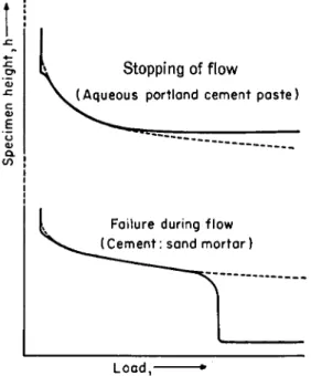
and σ is the applied uniaxial pressure. He considers the viscous element in the flow of the mortar paste as negligible. The difference in the behavior of the fresh set cement and the fresh mortar paste arises from his experi- ments by means of a parallel-plate compression apparatus, in which a cylinder of the material was compressed between two flat horizontal plates, both larger than the final cross section of the specimen. The total load Ρ was increased at a constant rate, and Fig. 2 shows the dependence of the height of the cylinder upon P. While the set cement paste can take high loads by mobilizing viscous resistance, the mortar paste fails in flow when the power input is excessive.
Lobanov6 extended his experiments mentioned in Section 11,2 above to mortars. In contradistinction to Roller he was able to determine the plastic viscosity of a 1:2 fresh cement mortar to be 3 4 poises. This need not be understood as contradicting Roller's results, considering the very different kinds of flow in their respective experiments. The yield stress was 9 5 0 dynes/cm.2, and the pumping pressure 21 atm.
2 . VISCOSITY OF SE T MORTAR
Bingham and Reiner13 included in their experiments 1:3 mortar beams.
Here also chemical hardening stopped at an age of approximately 4 5 days.
However, in contradistinction to the set cement beams, mortar beam
Load, •
FIG. 2. Behavior of building pastes in the compression apparatus
II/4 (compare Fig. 1) seemed to exhibit a more pronounced foreeffect. It was also found that the creep viscosity increases with increasing curing period and extrapolation to zero creep fluidity seemed to indicate that a beam cured for 80 days or more would not show any viscous creep under a stress of 5 X 10⁶ dynes/cm2. This would point to the existence of a yield stress. This feature has not been checked by later investigators, and in any case even if the admixture of sand to the cement would produce in the set mortar a yield value, this seems to be so low as to be negligible for all practical purposes.
Arnstein and Reiner14 observed mortar beams of 1:)^, 1:1, 1:2, 1:3, mixes and determined their creep viscosities as 67, 78, 82 and 88 in 1017
poises (within 10 to 20%) during a period of between 2 months and 1 year.18 These observations were carried out for the same loading conditions as mentioned for cement, namely own weight, and double and triple load.
Within the available accuracy, no yield point could be observed.
It was found that the ratio of creep viscosity of the 1:3 mortar to the one of set cement was approximately the same as in Bingham and Reiner's observations. This was the more remarkable as the rate of creep of set cement in the latter case was about four times the one in the former. The following conclusions were drawn: (a) The creep viscosity of the mortar depends, other factors being equal, upon the creep viscosity of the cement but not upon the nature of the sand, (b) The increase of creep viscosity of the mortar over that of set cement is the result of the interference of the solid sand particles with the flow of the quasi-fluid cement. In other words, it is the cement which creeps, and the sand forms a suspended solid phase.
On the other hand, an excess of free water in the mortar over that in the cement will decrease the creep viscosity of the former. Assuming
where 770 is the viscosity of the set cement and cw the volume concentra- tion of excess water in the cement base of the mortar, Arnstein and Reiner used a generalized Einstein formula.
where cv is the volume concentration of the sand in the cement base, and found that a turned out to be Einstein's factor = 2.5 which is valid for very dilute suspensions. Reiner19 explains this surprising result with the following words: "If the viscosity of the dispersion medium, in our case
1 8 They remark that the large spreading of observations was probably due to in- adequate moisture and temperature control.
1 9 M. Reiner, "Deformation and Flow: An Elementary Introduction to Theoretical Rheology." Lewis, London, 1949.
fio = 770 (1 - Cw) (2)
η = fjo (1 + «Cr) (3)
the cement base, is of the order of 1017 poises, the flow during one year will be too small to cause either an appreciable change in the orientation of [non spherical] sand particles or an interference [with the flow of the cement base] beyond the [taking-up] of volume proper of the particle. One year of the flow of cement is as much as 10~12 seconds in the flow of water.
If the observation (of the flow of an ordinary suspension) were to last 10~12 seconds only . . . a steady state of flow could not establish itself. To change the picture from a temporal to a spatial one : the distances between particles in a liquid of a viscosity of the order of 1017 poises are equivalent to distances in water 1019 times as great. We can [regard] the concentration of 60 percent in cement as [very] small in terms of concentration in water."
In order to prove this hypothesis it would be necessary to solve the mo- mentum equations of the Maxwell body15 for unsteady inhomogeneous flow, a mathematical feat which has not yet been attempted. Until then the equation
1 + WC
Vc = ηο χ _|_ (1 + 2.5 cv). (4)
for the creep viscosity r/c of the cement mortar of volume concentration cv of sand in the mortar, with WC the water-cement ratio of neat cement, and WC of the cement base in the mortar, which is derived from equations (2) and (3), must be considered as empirical.
These considerations are based upon the assumption that set cement can be considered as a viscous liquid. This view might have to be revised in consideration of Glückliche experiments with set cement mentioned in Sec. 111,3.
3. ELASTICITY OF SE T MO R T A R
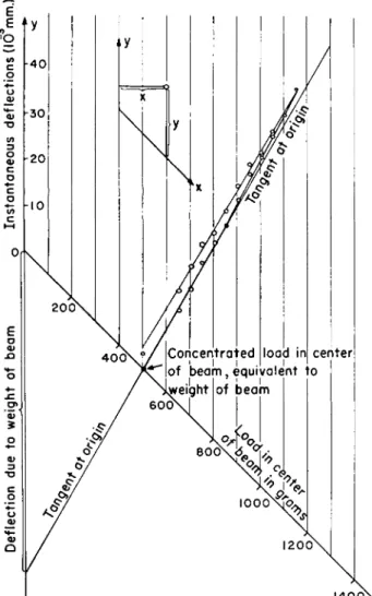
In order to determine the law of elasticity of set mortar Bingham and Reiner loaded beams at midspan in two different manners, (a) The weights were gradually increased to a maximum and likewise decreased, and deflections observed during the cycle as functions of loads. Each experi- ment took about 1 hr. (b) The beam was loaded with the full weight so that the loading did not take time, and the deflection was observed. This was repeated with increasing loads until a maximum had been reached.
It was found that procedure (a) resulted in a hysteresis loop, both branches being bent upward. Viscous flow could not produce such hys- teresis in 1 hr., and it therefore had to be due to delayed elasticity (com- pare Fig. 3). In case (b) the curve is sufficiently close to a straight line and its slope is the same as the slope of the tangent at the origin of curve (a).
The conclusion may be drawn that the instantaneous strain of set mortar within such sand concentrations as observed by Bingham and
É
FIG. 3. Stress-strain diagram for beam 11/14. An oblique coordinate system, as shown in the upper part of the graph, is used. Instantaneous deflections were under loads superimposed on the weight of the beam.
Reiner obeys Hooke's law. If consecutive strains are measured while the load is gradually increased in time, the strain-stress diagram will be curved and of parabolic shape, with its convex side toward the stress axis.
This curvature is due to delayed elasticity. Contrary to general opinions this seems also to apply to the coarse aggregate. Blakey and Beresford20
2 0 F . A. Blakey and F . D . Beresford, Report C2.2-1, Commonwealth Scientific In- dustrial Research Organization, Melbourne, Australia, 1953.
state that "there is little evidence of any deviation from a linear tensile stress-strain relationship for concrete below the cracking stress."
A Young modulus of about 28 X 1010 dynes/cm.2 was calculated for 1:3 mortars. This implied an increase of about 15% over the modulus of the set cement as mentioned in Section 111,3.
V. Concrete 1. FRESH CONCRETE
In the fresh concrete the fresh mortar forms the medium in which the coarse aggregate is suspended. The most important rheological properties of fresh concrete are (a) workability and (b) stability.
To evaluate workability, Herschel and Pisapia21 designed four tests which determine certain factors, supposed to be at least partially in- dependent of each other. Harshness, defined as that relative property which may be illustrated by the smoothness of an oversanded, compared with the roughness of an undersanded mix, is measured by the spread of the concrete on a flow table after a certain number of drops. Segregation, the partial or complete separation of one class of materials from a uniform mixture, is measured by the amount of mortar separated from concrete by jolting on the flow table. For shear resistance the shear box first evolved by Terzaghi and later developed by Casagrande for soils, is used. Finally stickiness, related to the adhesion or bond which keeps the individual particles of the concrete to cling together in a single mass, is measured by the vertical force required to separate a horizontal steel plate from the surface of a freshly made concrete.
LTIermite22 has investigated shear resistance in greater detail. He uses the apparatus shown in Fig. 4. By placing a piston loaded with a weight Ρ against the free surface of the concrete, a pressure ρ is obtained on the cutting plane. A horizontal displacement u is then forced upon the upper part of the box, and the corresponding reactive shearing force F measured.
Plotting F versus u we find a maximum F(p) — R(p) and a minimum F'(p). Plotting R and F' against ρ results in a Coulomb straight line, with cohesion C and angle of friction φ.
R = C + Kp, F' = σ + K'p (5)
The ratio ρ = K/K' is named the coefficient of interlocking. The area Ο AB represents the resilience
W &R(p)U/2 (6)
2 1 W. H. Herschel and E. A. Pisapia, J. Am. Concrete Inst. 32, 64 (1936).
2 2 R. L'Hermite, Rev. matériaux construct, et trav. publ. 405, (1949), available in English translation, Cement and Concrete Assoc. Transi. No. 9 (1949).
FIG. 4. L'Hermite's observations on shear resistance of fresh concrete. A , appa- ratus. B, shearing force (F) versus displacement (u). C, Maximum (R) and minimum (Ff) shearing force versus weight (P).
where U is the maximum shearing displacement. This is approximately = KpU/2 and the unit pressure ρ is = if {7/2. L'Hermite defines a coefficient of workability μ by
μ = 1/KU (7) For a concrete with "continuous" grading, 300 kg. cement/m.3 and WC =
0.65, he found Κ = 0.7, Κ' = 0.45, C = 0.05 kg./cm.2, ρ = 1.5, μ = 17.
In a more recent publication, L'Hermite10 describes another method, more elementary but better suited to field conditions, for measuring shear resistance of fresh concrete. This consists essentially of a rod with a grooved core drill which is being rotated inside the concrete mass at a constant speed. The maximum torque, reached at the moment of rupture, is meas- ured. If the pressure exerted normally by the concrete on the core is known and if an assumption is made with regard to the cohesion, then the angle of internal friction can be calculated.
A ''stable'' mix is defined by Forslind1 as one in which the aggregate is completely separated by the paste, and a random sampling shows the
same particle-size distribution, retaining these characteristics during transportation, placing, and compacting. The shearing stresses caused by gravitation must therefore not exceed the yield stress of the paste. The resistance to deformation decreases with increasing layer thickness. The deformability decreases with hindered particle rotation, and therefore with decreasing layer thickness.
The layer thickness depends upon the paste-aggregate ratio and the size distribution of aggregates. Forslind1 mentions two methods by means of which it is possible to ascertain whether a concrete mix is stable or not.
They are the remoulding test of Powers and the plastometers by Erickson and Forslind and Bergstroem.
2. RHEOLOGICAL BEHAVIOR OF SET CONCRETE
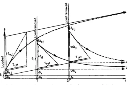
When a concrete (or reinforced concrete) slab is loaded, a deflection δ is produced (Arnan et ai.2 3). A certain part of the deflection occurs instanta- neously (δ{). When the load is removed immediately after loading24 part of the deflection (de.i) is recovered instantaneously; this is due to the stresses raised by the instantaneous strain. The rest which is not recovered is the "permanent set" (5S),2 5 so that
δΐ = δβ.ι + δδ ( 8 )
As regards δ8, this may be considered as a kind of plasticity without a noticeable yield point. To explain this, we must distinguish between macro- stresses and microstresses. The macrostress is the over-all stress as usually calculated in accordance with the theory of elasticity. However, every material body will have notches in its surface and voids or cracks in its interior. These cause local stress concentrations, and these microstresses will much exceed the over-all stress which is recorded in the stress-strain diagram. They will cause local ruptures in a brittle material such as con- crete. Therefore, there will be an irrecoverable macrodeformation, called the set, even at very low and practically infinitesimal macrostress, with a corresponding absence of yield point. This set is most pronounced on first loading. It is usually smaller at each further loading which does not exceed the first, and the elasticity of the material is accordingly improved through a series of loadings and unloadings. Arnan et α/.23 have shown how this affects the standard loading test for reinforced-concrete structures.
On the other hand, if we leave the slab under load for some time Τ, δ increases from δ* to δτ, and if we now remove the load we shall find, be-
2 3 A. Arnan, M. Reiner, and M. Teinowitz, "Research on Loading Tests of Rein- forced Concrete Structures." Research Council of Israel, Jerusalem, 1950.
2 4 Some time must elapse for reading observations, unloading, etc.
2 5 This is the set to which allusion is made in Section I.
Mfe
T3 < D
σ o
δ
T 2 T t
FIG. 5. Deformation-time curve for material with creep; δ = deflection; δ» = in- stantaneous deflection; 5e, <* = delayed elastic deflection (primary creep); δν = de- flection produced by viscous flow (secondary creep).
sides an instantaneous recovery of the same magnitude as before, that after a day or two still more is recovered, and that this process goes on for days and weeks up to a maximum of additional recovery 8d . This is a measure of the delayed strain consisting of elastic fore-effect on loading and elastic aftereffect on recovery, and an indication of the property of delayed elasticity. At the same time the nonrecovered permanent deforma- tion has also increased by, say, δυ . If we double the time of loading we may find that δυ has increased to roughly 2δν and δά to ηδά where 1 < η < 2.
If we leave the load on for infinite time, δα will not increase beyond a certain maximum δβ,ά which is the delayed elastic strain. If δν increases both with time and with the load roughly in direct proportion, as in liquids, it could be considered as a case of viscous deformation. When first discovered this phenomenon was called plastic deformation, but the rheological behavior described here on the example of concrete is typical for all materials which are not plastic. In rheology, the latter term is connected with plastic be- havior in the presence of a yield point, but what is colloquially called a plastic is not a plastic substance in the rheological sense. Fresh concrete, which can be moulded may accordingly be termed a plastic, but it is not a plastic substance after it has set as it does not possess a yield point. When an attempt is made to force upon it a large deformation it breaks in a brittle manner; mild steel, which is a plastic substance, can be deformed by impact but concrete cannot.
As the time-dependent deflections δβ,ά and δν proceed with low speed,
Γ element l-L M-body
coefficient G.
K-body
M = H-N element NM • coefficient η
K=H IΝ
FIG. 6. Model fora Burgers body; H = elastic Hooke element, Ν — viscous New- tonian element, M — viscoelastic Maxwell body, Κ = firmo-viscous Kelvin body.
The rheological coefficients are: in shear G, η; in extension Ε, λ; in cubical dilatation κ, R.
they are called creep. They can be separated by unloading only, and are then distinguished as primary or recoverable creep, which is a strain, and secondary or irrecoverable creep which is sometimes considered as a defor- mation resulting from slow viscous flow. The viscous nature of secondary creep was first stated by Glan ville2 6 with the words, "The movement ap- pears to be . . . in the nature of viscous flow." This points to concrete be- having in one respect as a Maxwell body.24 Primary creep can be represented by a Kelvin body.27 For both acting together the Burgers body,27 a model of which is shown in Fig. 6, is appropriate. In the foregoing we have not taken into account the fact that loading takes time, especially in a loading exper- iment when the load gradually increases from zero to the test load. An in- crease of load at constant rate will be accompanied by an increase of instantaneous strain at constant rate together with an increase of set at
2 6 W. H. Glanville, Bldg. Research Tech. Papers 12 (1930).
27 Cf. Vol. I, Chapter 1, Section VI, 5.
roughly constant rate. The Burgers body cannot represent such behavior.
Pâez has proposed an appropriate model, and Torroja1 has developed an analytical theory based upon it.
3. Viscous CREEP
From Glanville's observations the following creep viscosities of concrete at an age of two months can be calculated :
mix 1:1:2 1:2:4 1:3:6
η in 1017 poises 7.5-10.6 2.8-3.6 1.3-2.0
It is remarkable that in contradistinction to mortars the viscosity decreases with increase of the amount of aggregates in the mix. The reason is to be sought in the presence of voids and the fact that a 1:1:2 concrete, because of better grading, will have less pore space than a 1:2:4 concrete. Equation (4) is therefore not applicable to concretes but may be replaced by
I _L_ YfQ
* = 170 m m
d +
4 0 c* -
5 3 c*
2) (
9)
1 + w c
The viscosity thus calculated, or observed at the age of two months, gradu- ally increases in the course of time. This has three causes. There is firstly the chemical hardening of the cement base as described in Section 111,3 above. Secondly in the course of the deformation aggregates come into contact and develop solid friction between them. Thirdly cement and mortar flow into the voids, decrease the latter, and therefore increase the creep viscosity. The third phenomenon is called volume flow.28 While even solid rocks creep through geological periods, it may be assumed that for all practical (i.e., building) purposes the viscosity ultimately becomes in- finite and creep stops. Thomas29 has attempted to estimate the limiting value of creep when the creep during the first year is known. Freudenthal30 proposed the equation
1 0 ,
*·-ΪΤϋ'
( 1 0 )for the linear creep deformation as a function of t the period of action of the normal stress σ in kg./cm.2, t being measured in years. The parameters a
2 8 For more information on volume flow of concrete the reader is referred to M.
Reiner, Appl. Sei. Research Al, 475-488 (1949); M. Reiner, Bull. Research Council Israel.
2 9 F. G. Thomas, Structural Engineer 11, 69 (1933).
3 0 A. M. Freudenthal, Intern. Assoc. Bridge & Struct. Eng. 4, 249-264 (1936).
TABLE I
Parameters in Freudenthal's equation A ge in months
Parameters 1 3 12
a 60 25 5
b 4 2.5 1
and b depend upon the age of the concrete at t = 0, and have the values shown in Table I. The limiting creep value is accordingly (a/b) X 10~6.
The theory of secondary creep as a case of viscous flow is based on the assumption that creep and shrinkage are independent. However, as Lea and Lee31 have pointed out, this view has not been accepted without excep- tion and they quote a view, which they'think goes too far, that "the effect of loading is simply to increase the effect of shrinkage." L'Hermite32 also mentions observations according to which a loaded specimen swells under water more than an unloaded one which shrank. He draws the conclusion that creep and shrinkage cannot be separated. Rao33 has carried out exten- sive experiments to show that creep is mainly, if not totally, due to shrink- age, the movement being considerably reduced when the specimen is coated with asphalt or kept wet.
Davis and co-workers34 found that creep of concrete made with sand- stone aggregates is several times the creep of similar concrete made with limestone. It seems that only the seepage theory can account for this fact.
Others attribute creep to shrinkage. However, since irreversible creep is also present in concretes submerged in water, they are forced to conclude that rheological properties such as sliding and viscosity are also active.
Neville35 explains creep through a reconciliation of the seepage and vis- cous theories.
He maintains that what is normally measured as creep consists of "true"
creep (viscous in nature, with gradual transfer of load to the aggregate) and increased shrinkage (seepage due to evaporation and external force).
The magnitude of creep depends on the force applied and the properties of the concrete, but is independent of curing conditions, humidity, tempera- ture, etc. Variations in these parameters affect shrinkage only. This hy- pothesis would account for the magnitude of creep in water as being the resultant of negative shrinkage (swelling) and positive creep.
31 F. M. Lea and R. C. Lee, Building Research Station Note No. 984, (May 1946).
3 2 R. L'Hermite, "Idées actuelles sur la technologie du beton." Paris.
3 3 K. L. Rao. 4e Congr. Grands Barrges, (New Delhi) Ä.64 (1951).
3 4 R. E. D . Davis, H. E. Davis, and J. S. Hamilton, Am. Soc. Testing Materials, Proc. 34, 354-386 (1934).
3 5 A. M. Neville, J. Am. Concrete Inst. 27, 47-60 (1955).
VI. Reinforced Concrete
When designing a reinforced concrete structure there is a tendency to imagine each element to consist of more or less parallel fibres, some in compression (taken by the concrete), others in tension (taken by the steel), separated by a neutral layer. Chaulet36 has drawn attention to the well- known but disregarded fact that this division is entirely unreal. In every point of the body there is compression in one direction and at the same time tension in the direction normal to the first, with shear vanishing in both directions. If the reinforcement follows the tension trajectories, the element can be designed as if it consisted of an isotropic material. Tangential bond stresses do not arise, and hooks at the ends of reinforcing bars can generally be dispensed with. Deviations in the location of the reinforcement from practical considerations cause only secondary stresses.
The two methods of design in use are known as the elastic and the limit analysis. In the first it is assumed that the concrete is compressed and the steel stressed within their respective elastic ranges, while the concrete
"fibres" in tension have fractured. This is the standard method. In the second method the ultimate load corresponding to the fracture pattern is computed and divided by a suitable factor of safety. This method has been developed for steel structures when considering stresses in the plastic (St.
Venant) range. Kooharian37 has applied limit design methods to nonrein- forced voussoir concrete arches. Cowan38 has described the method in some detail, quoting Freudenthal.39 In a more recent paper Freudenthal40 has drawn attention to the fact that the limit design procedure if applied to concrete is essentially different from the "plastic" method used for struc- tural metals. In concrete, which is a viscoelastic material having no yield point, the so-called plastic redistribution of stresses is, in fact, the result of a localized fracture process, the spreading of which along a shear plane is temporarily blocked by the lower stresses in the surrounding material.
While in metals the truly plastic redistribution of nonuniform stresses is gradual and continuous, in concrete there is a sharp discontinuity of be- havior.
A method in which the viscous creep of the concrete transfers all stress differences to the steel was described by Lohr.41
In prestressed concrete self-stresses are produced in the reinforced con-
3 6 M. Chaulet, Trav. architect., construct, trav. publ. (Paris) 18, 295-300, 439-445 (1934); 19, 172-177, 279-283 (1935).
37 A. Kooharian, J. Am. Concrete Inst. 24, 317-328 (1950).
38 H. J. Cowan, Engineering 276-278 (1952).
3 9 A. M. Freudenthal, "The Inelastic Behavior of Engineering Materials and Structures." Wiley, New York, 1950.
4 0 A.M. Freudenthal, Froc. 1st U. S. Natl. Congr. Appl. Mech. pp. 641-646 (1952).
41 W. S. Lohr, Eng. News-Record December (1934).
crête structure by putting the steel into tension, thus reducing both tension and compression in the concrete (compare Abeles4 2). Olszak43 has treated the problem of prestressing helically bound columns.
Nomenclature
a, b Parameters R Maximum resistance
A. Angstrom unit s Set
CV Volume concentration Τ Period of time
C Cohesion U Shearing displacement
d Thickness ν Viscous
dv Volume displacement WC Water-cement ratio Dc Creep deformation μ Coefficient of workability
e Elastic VPI Plastic viscosity
F Shearing force σ Uniaxial pressure
F' Minimum shearing force a Einstein factor
i Instantaneous δ Deflection
Κ Coefficient of renitence, coefficient Ρ Coefficient of interlocking
of friction Φ Angle of friction
4 2 P. W. Abeles, "Prestressed Concrete." Crosby Lockwood, London, 1952.
4 3 W. Olszak, Arch. Mécanique appl., Gdansk pp. 80-98 (1949).