Component-Based Software Development
Szendrei, Rudolf
Component-Based Software Development
írta Szendrei, Rudolf Publication date 2015
Szerzői jog © 2015 Szendrei Rudolf
Tartalom
Component-Based Software Development ... 1
1. 1 Introduction ... 1
1.1. Introduction ... 1
1.2. Introduction ... 1
1.3. Introduction ... 1
1.4. Introduction ... 1
1.5. 1.1 Software development ... 2
1.5.1. Software development ... 2
1.5.2. Software development ... 2
1.5.3. Software development ... 2
1.5.4. 1.1.1 Component-based Software Development ... 3
1.5.5. Component-based Software Development ... 3
1.5.6. Component-based Software development ... 3
1.5.7. 1.1.2 Concepts of component ... 3
1.5.8. Concepts of component ... 3
1.5.9. Composition ... 4
1.5.10. Composition - UML diagram ... 4
1.5.11. Interface ... 4
1.5.12. Client-Server connection ... 4
1.5.13. UML representation of the required and provided interfaces of the component 5 2. 2 UML, IDL ... 5
2.1. 2.1 UML ... 5
2.2. 2.2 Modeling in UML ... 5
2.3. 2.3 Structural diagrams ... 5
2.3.1. Structural diagrams ... 5
2.3.2. 2.3.1 Package diagram ... 6
2.3.3. Package diagram ... 6
2.3.4. 2.3.2 Class diagram ... 6
2.3.5. Class diagram ... 6
2.3.6. Class diagram ... 7
2.3.7. 2.3.3 Object diagram ... 7
2.3.8. Object diagram ... 7
2.3.9. 2.3.4 Composite structural diagram ... 7
2.3.10. Composite structural diagram ... 7
2.3.11. Composite structural diagram ... 8
2.3.12. Composite structural diagram ... 8
2.3.13. Composite structural diagram ... 8
2.3.14. Composite structural diagram ... 8
2.3.15. Composite structural diagram ... 9
2.3.16. Composite structural diagram ... 9
2.3.17. Composite structural diagram ... 9
2.3.18. Composite structural diagram ... 9
2.3.19. 2.3.5 Component diagram ... 10
2.3.20. Component diagram ... 10
2.3.21. Component diagram ... 10
2.3.22. Component diagram ... 10
2.3.23. 2.3.6 Deployment diagram ... 11
2.3.24. Deployment diagram ... 11
2.3.25. 2.3.7 Artifact, Installation association ... 11
2.3.26. Artifact, Installation association ... 11
2.4. 2.4 Behavioral diagrams ... 11
2.4.1. Behavioral diagram ... 11
2.4.2. 2.4.1 Use case diagram ... 12
2.4.3. Use case diagram ... 12
2.4.4. 2.4.2 Activity diagram ... 12
2.4.5. Activity diagram ... 12
2.4.6. Activity diagram - example ... 13
2.4.7. 2.4.3 State-machine diagram ... 13
2.4.8. State-machine diagram ... 13
2.4.9. State-machine diagram ... 13
2.4.10. 2.4.4 Communication diagram ... 14
2.4.11. Communication diagram ... 14
2.4.12. 2.4.5 Sequence diagram ... 14
2.4.13. Sequence diagram ... 14
2.4.14. 2.4.6 Timing diagram ... 14
2.4.15. Timing diagram ... 15
2.4.16. 2.4.7 Interaction overview diagram ... 15
2.4.17. Interaction overview diagram ... 15
2.5. 2.5 IDL ... 15
2.5.1. Interface Definition Language ... 15
2.5.2. Interface Definition Language ... 16
2.5.3. Interface Definition Language ... 16
2.5.4. Interface Definition Language ... 16
2.5.5. Interface Definition Language ... 17
2.5.6. Interface Definition Language ... 17
2.5.7. Interface Definition Language - Example ... 17
3. 3 Software architectures ... 18
3.1. Software architecture ... 18
3.2. Software architecture ... 18
3.3. Software architecture - Analysis of the definition ... 18
3.4. Software architecture - Analysis of the definition ... 18
3.5. Software architecture ... 18
3.6. Relations of architecture schemas, reference models, reference architectures and software architectures ... 19
3.7. 3.0.1 Architecture schema ... 19
3.8. Software architecture ... 19
3.9. 3.0.2 Reference models ... 19
3.10. Software architecture ... 19
3.11. 3.0.3 Reference architecture ... 19
3.12. Software architecture ... 19
3.13. 3.0.4 Software architecture ... 20
3.14. Software architecture ... 20
3.15. 3.0.5 Common software architecture structures ... 20
3.16. Common software architecture structures ... 20
3.17. 3.0.6 Model based structure ... 20
3.18. The model based structure ... 20
3.19. The model based structure ... 21
3.20. 3.0.7 Component-and-connector structure ... 21
3.21. Component-and-connector structure ... 21
3.22. Component-and-connector structure ... 21
3.23. Component-and-connector structure ... 21
3.24. 3.0.8 Allocation structure ... 22
3.25. Allocation structure ... 22
3.26. Allocation structure ... 22
3.27. Software architecture ... 22
3.28. 3.1 Component models ... 22
3.28.1. Component models ... 22
3.28.2. 3.1.1 Middleware ... 22
3.28.3. Component models ... 23
3.28.4. Component models ... 23
3.28.5. Component models ... 23
3.28.6. Component models ... 23
3.29. 3.2 CORBA ... 24
3.29.1. CORBA ... 24
3.29.2. 3.2.1 Object Request Broker ... 24
3.29.3. CORBA ... 24
3.29.4. CORBA - ORB ... 24
3.29.5. CORBA - ORB ... 25
3.29.6. CORBA - ORB ... 25
3.29.7. 3.2.2 Object Adapter ... 25
3.29.8. CORBA ... 25
3.29.9. 3.2.3 Implementation Repository, ORB interface ... 25
3.29.10. CORBA ... 25
3.29.11. 3.2.4 IDL ... 26
3.29.12. CORBA - IDL ... 26
3.29.13. CORBA - IDL ... 26
3.29.14. CORBA - IDL ... 26
3.29.15. Generated code execution within the CORBA infrastructure ... 27
3.30. 3.3 COM/DCOM ... 27
3.30.1. COM/DOM ... 27
4. 4 JavaBeans ... 27
4.1. 4.1 Introduction ... 27
4.1.1. Introduction ... 27
4.2. 4.2 JavaBeans ... 28
4.2.1. JavaBeans ... 28
4.2.2. JavaBeans ... 28
4.2.3. 4.2.1 Enterprise Java Bean ... 28
4.2.4. JavaBeans - EJB ... 28
4.2.5. 4.2.2 J2EE overview ... 29
4.2.6. Java2EE ... 29
4.2.7. Quality requirements of web-application ... 29
4.2.8. ... 29
4.2.9. 4.2.3 J2EE - EJB overview ... 30
4.2.10. J2EE - EJB ... 30
4.2.11. J2EE - Tasks of EJB ... 30
4.2.12. Properties of J2EE ... 30
4.2.13. 4.2.4 J2EE - architecture ... 31
4.2.14. Architecture of J2EE ... 31
4.2.15. J2EE - Client layer ... 31
4.2.16. J2EE - Web layer ... 31
4.2.17. J2EE - Business component layer ... 31
4.2.18. J2EE - Enterprise information systems tier ... 32
4.2.19. 4.2.5 J2EE - EJB architecture ... 32
4.2.20. J2EE - EJB architecture ... 32
4.2.21. J2EE - EJB architecture ... 32
4.2.22. J2EE - EJB container ... 33
4.2.23. J2EE - Component model ... 33
4.2.24. J2EE - EJB Component types ... 33
4.2.25. 4.2.6 J2EE - EJB component types ... 34
4.2.26. J2EE - EJB Component types ... 34
4.2.27. J2EE - EJB Component types - Entity beans ... 34
4.2.28. J2EE - EJB Component types - Entity beans ... 34
4.2.29. J2EE - Example for J2EE/EJB-compliant implementation ... 34
4.2.30. 4.2.7 J2EE - EJB programming ... 35
4.2.31. J2EE - EJB programming ... 35
4.2.32. J2EE - Creating a server side bean ... 35
4.2.33. J2EE - EJB program units ... 35
4.2.34. J2EE Example - The realizer class ... 36
4.2.35. 4.2.8 Deployment descriptors ... 38
4.2.36. J2EE - Deployment descriptors ... 38
4.2.37. 4.2.9 Summary ... 39
4.2.38. Summary ... 39
5. 5 KobrA program-development model ... 39
5.1. KobrA ... 39
5.2. KobrA ... 40
5.3. KobrA ... 40
5.4. 5.0.1 Development process ... 40
5.5. KobrA ... 40
5.6. KobrA ... 41
5.7. KobrA ... 41
5.8. KobrA ... 41
5.9. 5.0.2 Decomposition ... 42
5.10. KobrA ... 42
5.11. KobrA ... 42
5.12. KobrA - Vending-machine problem decomposition ... 42
5.13. KobrA ... 42
5.14. 5.0.3 Embodiment ... 43
5.15. KobrA ... 43
5.16. KobrA ... 43
5.17. 5.0.4 Composition ... 43
5.18. KobrA ... 43
5.19. 5.0.5 Validation ... 43
5.20. KobrA ... 43
5.21. 5.0.6 Spiral model ... 44
5.22. KobrA ... 44
5.23. 5.0.7 Waterfall model ... 44
5.24. KobrA ... 44
5.25. 5.0.8 Example ... 44
5.26. KobrA - Vending machine UML diagram ... 44
5.27. KobrA ... 45
5.28. 5.1 Environmental map ... 45
5.28.1. ... 45
5.28.2. KobrA - Environmental map ... 45
5.28.3. KobrA - Environmental map - Example ... 45
5.28.4. KobrA - Environmental map ... 46
5.28.5. KobrA - Environmental map ... 46
5.28.6. KobrA - Environmental map elements ... 46
5.28.7. KobrA - Environmental map ... 47
5.28.8. 5.1.1 Usage model ... 47
5.28.9. KobrA - Environmental map ... 47
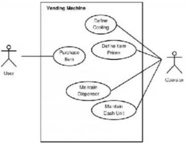
5.28.10. KobrA - Usage model - Vending machine's use case diagram ... 47
5.28.11. KobrA - Environmental map ... 48
5.28.12. KobrA - Environmental map - Use case template ... 48
5.28.13. KobrA - Vending machine - Purchase item use case ... 48
5.28.14. 5.1.2 Business and enterprise processes model ... 49
5.28.15. KobrA - Environmental map ... 49
5.28.16. KobrA - Environmental map ... 49
5.28.17. 5.1.3 Structural model ... 50
5.28.18. KobrA - Environmental map ... 50
5.28.19. KobrA - Structural model of a variant inside the environmental map ... 50
5.28.20. KobrA - Environmental map ... 50
5.28.21. 5.1.4 Activity and interaction model ... 51
5.28.22. KobrA - Environmental map ... 51
5.28.23. KobrA - Activity diagram - Vending machine - Purchase Item ... 51
5.28.24. KobrA - Environmental map ... 51
5.28.25. 5.1.5 Summary ... 52
5.28.26. KobrA - Environmental map ... 52
5.28.27. KobrA - Activities of a customer of the Vending machine ... 52
5.28.28. KobrA - Environmental map ... 52
5.28.29. KobrA - Component meta-model diagram ... 52
5.28.30. KobrA - Environmental map ... 53
6. 6 KobrA - Component specification and implementation ... 53
6.1. 6.1 Component specification ... 53
6.1.1. 6.1.1 Component specification ... 53
6.1.2. Component specification ... 53
6.1.3. Component specification ... 53
6.1.4. Component specification ... 54
6.1.5. 6.1.2 Structural specification ... 54
6.1.6. Component specification ... 55
6.1.7. Component specification ... 55
6.1.8. Component specification ... 56
6.1.9. 6.1.3 Operation specification ... 56
6.1.10. Component specification ... 56
6.1.11. Operation specification template according to the KobrA method and Fusion 56 6.1.12. Operation specification of the Vending machine ... 57
6.1.13. 6.1.4 Behavioral specification ... 57
6.1.14. Component specification ... 57
6.1.15. Component specification ... 58
6.1.16. Component specification ... 58
6.1.17. Behavioral specification of the Vending machine in the form of a state transition table ... 59
6.2. 6.2 Component realization ... 59
6.2.1. 6.2.1 Component realization ... 59
6.2.2. Component realization ... 59
6.2.3. Component realization ... 60
6.2.4. 6.2.2 Structural specification ... 60
6.2.5. Component realization ... 60
6.2.6. Component realization ... 61
6.2.7. Component realization ... 61
6.2.8. Component realization ... 62
6.2.9. 6.2.3 Realization algorithms ... 62
6.2.10. Component realization ... 62
6.2.11. 6.2.4 Structural specification ... 63
6.2.12. Component realization ... 63
6.2.13. Component realization ... 63
6.2.14. 6.2.5 Specification of realization interaction ... 64
6.2.15. Component realization ... 64
6.3. 6.3 Summary ... 64
6.3.1. Summary ... 64
7. 7 KobrA - Component embodiment, Normal Object Form ... 65
7.1. 7.1 Component embodiment ... 65
7.1.1. Component embodiment ... 65
7.1.2. Component embodiment ... 65
7.1.3. Component embodiment ... 66
7.1.4. Refinement and translation (Manual Translation) in a single step ... 66
7.1.5. Component embodiment ... 66
7.1.6. Component embodiment ... 67
7.1.7. Component embodiment - SORT technique ... 67
7.1.8. Component embodiment - SORT technique ... 67
7.1.9. Refinement and translation in two separated steps ... 67
7.1.10. Component embodiment ... 68
7.2. 7.2 Normal Object Form ... 68
7.2.1. Normal Object Form ... 68
7.2.2. Normal Object Form ... 68
7.2.3. Normal Object Formt ... 69
7.2.4. SORT ... 69
7.2.5. SORT ... 69
7.2.6. Component embodiment ... 69
7.2.7. Component embodiment - Component reusage ... 70
7.2.8. Component embodiment ... 70
7.2.9. Component embodiment ... 70
7.2.10. Component embodiment ... 70
7.2.11. Containment hierarchy for the CashUnit ... 71
7.2.12. Component Of The Shelf ... 71
7.2.13. Custom-designed vs. third-party component integration ... 71
7.2.14. Component Of The Shelf ... 71
7.2.15. Component Of The Shelf ... 72
8. 8 System development from "Off the shelf" components ... 72
8.1. 8.1 Components of the Shelf ... 72
8.1.1. Components of the Shelf ... 72
8.1.2. Components of the Shelf ... 72
8.1.3. Components of the Shelf ... 73
8.1.4. Components of the Shelf ... 73
8.1.5. 8.1.1 Example ... 73
8.1.6. Components of the Shelf ... 73
8.1.7. Components of the Shelf ... 73
8.1.8. Components of the Shelf ... 73
8.1.9. Components of the Shelf ... 74
8.1.10. 8.1.2 Effects of the components ... 74
8.1.11. Components of the Shelf ... 74
8.1.12. Components of the Shelf ... 74
8.1.13. Components of the Shelf ... 74
8.1.14. Components of the Shelf ... 74
8.1.15. 8.1.3 Architectural differences ... 74
8.1.16. Components of the Shelf ... 75
8.1.17. Components of the Shelf ... 75
8.1.18. Components of the Shelf ... 75
8.1.19. Components of the Shelf - Architectural difference ... 75
8.1.20. Components of the Shelf ... 75
8.1.21. Components of the Shelf ... 76
8.1.22. Components of the Shelf ... 76
8.1.23. Components of the Shelf - Architectural difference ... 76
8.1.24. Components of the Shelf ... 76
8.1.25. 8.1.4 Designing as browsing components ... 77
8.1.26. Components of the Shelf ... 77
8.1.27. Components of the Shelf ... 77
8.1.28. Components of the Shelf ... 77
8.1.29. 8.1.5 Session of Model problem in 6 steps ... 77
8.1.30. Components of the Shelf ... 77
8.1.31. Components of the Shelf - The session of the model problem ... 78
8.1.32. 8.1.6 Example - ASEILM ... 78
8.1.33. Components of the Shelf ... 78
8.1.34. Components of the Shelf ... 78
8.1.35. ASEILM - Quality Attribute Requirements ... 79
8.1.36. 8.1.7 ASEILM - Miva Empressa ... 79
8.1.37. Components of the Shelf ... 79
8.1.38. Components of the Shelf - Miva Empressa ensemble ... 80
8.1.39. 8.1.8 Miva Empressa - System Model ... 80
8.1.40. Components of the Shelf ... 80
8.1.41. Components of the Shelf ... 80
8.1.42. Components of the Shelf ... 80
8.1.43. Components of the Shelf - Introduction of Proxy server ... 81
8.1.44. Components of the Shelf ... 81
8.1.45. Components of the Shelf ... 81
8.1.46. Components of the Shelf ... 81
8.1.47. Components of the Shelf - JavaServer Pages ensemble ... 82
8.1.48. Components of the Shelf ... 82
8.1.49. Components of the Shelf - Layers of custom component ... 82
8.2. 8.2 Summary ... 82
8.2.1. Summary ... 82
9. 9 SYNTHESIS Tool ... 83
9.1. 9.1 SYNTHESIS Tool ... 83
9.1.1. SYNTHESIS A Tool to assembly automatically a correct, distributed component- based system ... 83
9.1.2. SYNTHESIS ... 83
9.1.3. 9.1.1 COM/DCOM ... 83
9.1.4. SYNTHESIS ... 83
9.1.5. SYNTHESIS ... 84
9.1.6. SYNTHESIS ... 84
9.1.7. SYNTHESIS ... 84
9.1.8. SYNTHESIS ... 85
9.1.9. 9.1.2 Applied architecture ... 85
9.1.10. SYNTHESIS ... 85
9.1.11. SYNTHESIS ... 85
9.1.12. SYNTHESIS ... 86
9.1.13. 9.1.3 Formalization of configuration ... 86
9.1.14. Formalization of the configuration ... 86
9.1.15. Formalization of the configuration ... 86
9.1.16. Formalization of the configuration ... 87
9.1.17. Formalization of the configuration ... 87
9.1.18. Formalization of the configuration ... 87
9.1.19. Formalization of the configuration ... 87
9.1.20. Formalization of the configuration ... 88
9.1.21. Formalization of the configuration ... 88
9.1.22. Formalization of the configuration ... 88
9.1.23. Formalization of the configuration ... 89
9.1.24. Formalization of the configuration ... 89
9.1.25. Formalization of the configuration ... 89
9.1.26. 9.1.4 SYNTHESIS method ... 90
9.1.27. SYNTHESIS method ... 90
9.1.28. SYNTHESIS method ... 90
9.1.29. SYNTHESIS method ... 90
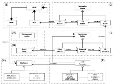
9.1.30. 9.1.5 SYNTHESIS's architecture ... 90
9.1.31. SYNTHESIS - Architecture ... 90
9.1.32. SYNTHESIS - Architecture ... 91
9.2. 9.2 1st Phase ... 91
9.2.1. SYNTHESIS - Architecture ... 91
9.2.2. SYNTHESIS - Architecture ... 91
9.2.3. 9.2.1 Architecture - Module A ... 91
9.2.4. SYNTHESIS - Architecture ... 92
9.2.5. 9.2.2 Architecture - Module B ... 92
9.2.6. SYNTHESIS - Architecture ... 92
9.2.7. SYNTHESIS - Architecture ... 92
9.2.8. SYNTHESIS - Architecture ... 92
9.2.9. SYNTHESIS - Architecture ... 93
9.2.10. SYNTHESIS - Architecture ... 93
9.2.11. 9.2.3 Architecture - Module C ... 93
9.2.12. SYNTHESIS - Architecture ... 93
9.2.13. SYNTHESIS - Architecture ... 94
9.2.14. SYNTHESIS - Architecture ... 94
9.2.15. SYNTHESIS - Architecture ... 94
9.2.16. SYNTHESIS - Architecture ... 95
9.2.17. SYNTHESIS - Architecture ... 95
9.2.18. 9.2.4 Architecture - Module D ... 95
9.2.19. SYNTHESIS - Architecture ... 95
10. 10 Object lifecycle, Temporal logic ... 95
10.1. 10.1 Object's lifycycle ... 96
10.1.1. 10.1.1 Introduction ... 96
10.1.2. Object's lifecycle ... 96
10.1.3. Object's lifecycle ... 96
10.1.4. Object's lifecycle ... 96
10.1.5. 10.1.2 Technology characteristics ... 97
10.1.6. Object's lifecycle ... 97
10.1.7. 10.1.3 Proposition Temporal Logic (PTL) ... 97
10.1.8. Object's lifecycle ... 97
10.1.9. Object's lifecycle ... 98
10.1.10. Object's lifecycle ... 98
10.1.11. Object's lifecycle ... 98
10.1.12. Object's lifecycle ... 99
10.1.13. Object's lifecycle ... 99
10.1.14. 10.1.4 Model ... 99
10.1.15. Object's lifecycle ... 99
10.1.16. Object's lifecycle ... 100
10.1.17. Object's lifecycle ... 100
10.1.18. Object's lifecycle ... 100
10.1.19. Object's lifecycle ... 100
10.1.20. Figure 2. The AIRPLANE role specification ... 101
10.1.21. Object's lifecycle ... 101
10.1.22. Object's lifecycle ... 102
10.1.23. Object's lifecycle ... 102
10.1.24. Object's lifecycle ... 102
10.1.25. Object's lifecycle ... 102
10.1.26. Object's lifecycle ... 103
10.1.27. Figure 4. Lifecycle context of Airplane ... 103
10.1.28. Figure 4. Lifecycle context of Airplane - continued ... 104
10.1.29. Figure 5. Constraints relative to the context PLANE_LIFE ... 104
10.1.30. Object's lifecycle ... 105
10.1.31. 10.1.5 Examples ... 105
10.1.32. Object's lifecycle ... 105
10.1.33. Object's lifecycle ... 105
10.1.34. Object's lifecycle ... 106
10.1.35. Object's lifecycle ... 106
10.1.36. Object's lifecycle ... 106
10.1.37. Figure 7. Example of a constraint relating a message and the playing of a role. 106 10.1.38. Figure 8. Example of a constraint relating two messages of distinct role. 107 10.1.39. 10.1.6 Satisfiability algorithm ... 107
10.1.40. Object's lifecycle ... 107
10.1.41. Object's lifecycle ... 108
10.1.42. Object's lifecycle ... 108
10.1.43. Object's lifecycle ... 108
10.1.44. Object's lifecycle ... 108
10.1.45. Object's lifecycle ... 108
10.1.46. 10.1.7 Literature ... 109
10.1.47. Object's lifecycle ... 109
11. 11 Verification, validation ... 109
11.1. 11.1 verification and validation ... 109
11.1.1. 11.1.1 Notions ... 109
11.1.2. Verification and validation of component-based systems ... 109
11.1.3. Verification and validation of component-based systems ... 109
11.1.4. 11.1.2 Historical overview ... 110
11.1.5. Verification and validation of component-based systems ... 110
11.1.6. Verification and validation of component-based systems ... 110
11.1.7. Verification and validation of component-based systems ... 110
11.1.8. 11.1.3 Correctness proof methods ... 111
11.1.9. Verification and validation of component-based systems ... 111
11.1.10. 11.1.4 Testing ... 111
11.1.11. Verification and validation of component-based systems ... 111
11.1.12. Verification and validation of component-based systems ... 111
11.1.13. Verification and validation of component-based systems ... 112
11.1.14. Verification and validation of component-based systems ... 112
11.1.15. 11.1.5 Test environment ... 112
11.1.16. Verification and validation of component-based systems ... 112
11.1.17. Verification and validation of component-based systems ... 113
11.1.18. 11.1.6 Model based testing ... 113
11.1.19. Verification and validation of component-based systems ... 113
11.1.20. Verification and validation of component-based systems ... 114
11.1.21. Verification and validation of component-based systems ... 114
11.1.22. Verification and validation of component-based systems ... 114
11.1.23. Verification and validation of component-based systems ... 114
11.1.24. 11.1.7 Testing techniques ... 115
11.1.25. Verification and validation of component-based systems ... 115
11.1.26. Verification and validation of component-based systems ... 115
11.1.27. Verification and validation of component-based systems ... 115
11.1.28. Verification and validation of component-based systems ... 115
11.1.29. 11.1.8 Model based testing ... 116
11.1.30. Verification and validation of component-based systems ... 116
11.1.31. Verification and validation of component-based systems ... 116
11.1.32. Verification and validation of component-based systems ... 117
11.1.33. Verification and validation of component-based systems ... 117
11.1.34. Verification and validation of component-based systems ... 117
11.1.35. Verification and validation of component-based systems ... 117
11.1.36. Verification and validation of component-based systems ... 118
11.1.37. Verification and validation of component-based systems ... 118
11.1.38. Verification and validation of component-based systems ... 118
11.1.39. Verification and validation of component-based systems ... 119
11.1.40. Verification and validation of component-based systems ... 119
11.1.41. Verification and validation of component-based systems ... 119
11.1.42. Verification and validation of component-based systems ... 119
11.1.43. Verification and validation of component-based systems ... 120
11.1.44. Verification and validation of component-based systems ... 120
11.1.45. Verification and validation of component-based systems ... 121
11.1.46. Verification and validation of component-based systems ... 121
11.1.47. Verification and validation of component-based systems ... 122
11.1.48. Verification and validation of component-based systems ... 122
11.1.49. Verification and validation of component-based systems ... 122
11.1.50. Verification and validation of component-based systems ... 123
11.1.51. Verification and validation of component-based systems ... 123
11.1.52. Verification and validation of component-based systems ... 123
11.1.53. Verification and validation of component-based systems ... 124
11.1.54. Verification and validation of component-based systems ... 124
11.1.55. Verification and validation of component-based systems ... 125
11.1.56. Verification and validation of component-based systems ... 125
11.1.57. Verification and validation of component-based systems ... 125
11.1.58. Verification and validation of component-based systems ... 125
11.1.59. Verification and validation of component-based systems ... 125
11.1.60. Verification and validation of component-based systems ... 126
11.1.61. Verification and validation of component-based systems ... 126
11.1.62. Verification and validation of component-based systems ... 126
11.1.63. Verification and validation of component-based systems ... 127
11.1.64. Verification and validation of component-based systems ... 127
11.1.65. Verification and validation of component-based systems ... 128
11.1.66. Verification and validation of component-based systems ... 128
11.1.67. Verification and validation of component-based systems ... 129
11.1.68. Verification and validation of component-based systems ... 129
11.1.69. Verification and validation of component-based systems ... 129
11.1.70. Verification and validation of component-based systems ... 129
11.1.71. Verification and validation of component-based systems ... 130
11.1.72. Verification and validation of component-based systems ... 130
11.1.73. Verification and validation of component-based systems ... 130
11.1.74. Verification and validation of component-based systems ... 131
11.1.75. Verification and validation of component-based systems ... 131
11.1.76. Verification and validation of component-based systems ... 131
11.1.77. Verification and validation of component-based systems ... 131
11.1.78. Verification and validation of component-based systems ... 132
11.1.79. Verification and validation of component-based systems ... 132
11.1.80. Verification and validation of component-based systems ... 132
11.1.81. Verification and validation of component-based systems ... 132
11.1.82. Verification and validation of component-based systems ... 133
11.1.83. Verification and validation of component-based systems ... 133
11.1.84. 11.1.9 Test infrastructure ... 133
11.1.85. Verification and validation of component-based systems ... 134
11.1.86. 11.1.10 Aspects of testing ... 134
11.1.87. Verification and validation of component-based systems ... 134
11.1.88. Verification and validation of component-based systems ... 134
11.1.89. Verification and validation of component-based systems ... 135
11.1.90. Verification and validation of component-based systems ... 135
11.1.91. Verification and validation of component-based systems ... 136
11.1.92. Verification and validation of component-based systems ... 136
12. 12 Verification Problems ... 136
12.1. 12.1 Verification of CBSD ... 136
12.1.1. 12.1.1 Component-Based software development ... 136
12.1.2. Component-Based software development ... 136
12.1.3. 12.1.2 Important properties for software components ... 137
12.1.4. Component-Based software development ... 137
12.1.5. Component-Based software development ... 137
12.1.6. Component-Based software development ... 137
12.1.7. 12.1.3 Verification problems of CBSD ... 138
12.1.8. Component-Based software development ... 138
12.1.9. Component-Based software development ... 138
12.1.10. 12.1.4 Model checking ... 138
12.1.11. Component-Based software development ... 138
12.1.12. 12.1.5 Usage model ... 139
12.1.13. Component-Based software development ... 139
12.1.14. 12.1.6 Verification of the usage model ... 139
12.1.15. Component-Based software development ... 139
12.1.16. Component-Based software development ... 139
12.1.17. The model and the specification in NuSMV ... 139
12.1.18. Component-Based software development ... 140
12.1.19. Component-Based software development ... 140
12.1.20. Corresponding parts of Use Case description and NuSMV specification 141 12.1.21. Fair and violating behaviour (1) ... 141
12.1.22. Fair and violating behaviour (2) ... 142
12.1.23. 12.1.7 Conclusions ... 142
12.1.24. Component-Based software development ... 142
12.1.25. 12.1.8 References ... 142
12.1.26. Component-Based software development ... 142
12.1.27. Component-Based software development ... 143
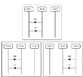
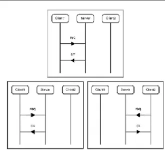
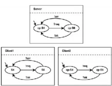
12.2. 12.2 Example - A railway problem ... 143
12.2.1. Counter-example ... 144
12.2.2. Counter-example ... 145
12.2.3. Counter-example ... 146
12.2.4. Counter-example ... 146
12.2.5. Counter-example ... 146
12.2.6. Counter-example ... 147
12.2.7. Counter-example ... 147
12.2.8. Counter-example ... 147
12.2.9. Counter-example ... 147
12.2.10. Counter-example ... 147
12.2.11. Counter-example ... 148
12.2.12. Counter-example ... 148
12.2.13. Counter-example ... 148
12.2.14. Counter-example ... 148
12.2.15. Counter-example ... 149
12.2.16. Counter-example ... 149
13. 13 Model checkers ... 149
13.1. 13.1 Model checkers ... 149
13.1.1. 13.1.1 Component-based software technology ... 149
13.1.2. Model checkers ... 149
13.1.3. 13.1.2 Component-based software development ... 150
13.1.4. Model checkers ... 150
13.1.5. 13.1.3 Contracts ... 150
13.1.6. Model checkers ... 150
13.1.7. Model checkers ... 150
13.1.8. Model checkers ... 150
13.1.9. Model checkers ... 151
13.1.10. 13.1.4 Verified components ... 151
13.1.11. Verified components ... 151
13.1.12. A component, that realizes mutual exclusion ... 151
13.1.13. 13.1.5 Peterson's method ... 152
13.1.14. Peterson's method (1981) - First process ... 152
13.1.15. Peterson's method - Second process ... 152
13.1.16. 13.1.6 Correctness ... 152
13.1.17. Model checking ... 152
13.1.18. Model checking ... 152
13.1.19. Model checking ... 153
13.1.20. 13.1.7 Symbolic Model Verifier ... 153
13.1.21. Model checking ... 153
13.1.22. Model checking ... 154
13.1.23. MODULE prc(state0, state1, turn, turn0) ... 154
13.1.24. MODULE prc - cont. ... 154
13.1.25. Model checking ... 154
13.1.26. 13.1.8 A model of parallel computation ... 154
13.1.27. Model checking ... 154
13.1.28. Model checking ... 155
13.1.29. Model checking ... 155
13.1.30. Model checking ... 155
13.1.31. Model checking ... 156
13.1.32. Model checking ... 156
13.1.33. Model checking ... 156
13.1.34. Model checking ... 156
13.1.35. Model checking ... 157
13.1.36. 13.1.9 Combination of model checkers and testing ... 157
13.1.37. Model checking ... 157
13.1.38. 13.1.10 Example ... 157
13.1.39. Component-Based software development ... 157
13.1.40. Component-Based software development ... 158
13.1.41. The model and the specification in NuSMV ... 158
13.1.42. Model checking ... 159
13.1.43. Fair and violating behaviour (1) ... 159
13.1.44. Model checking ... 159
13.1.45. Fair and violating behaviour (2) ... 160
13.1.46. Model checking ... 160
13.1.47. 13.1.11 References ... 160
13.1.48. CBSD - Model checkers ... 160
13.1.49. CBSD - Model checkers ... 160
14. 14 Common Component Modeling ... 161
14.1. 14.1 Common Component Modelling ... 161
14.1.1. 14.1.1 Modelling of a trading system ... 161
14.1.2. Common Component Modelling ... 161
14.1.3. Common Component Modelling ... 161
14.1.4. Common Component Modelling ... 162
14.1.5. Common Component Modelling ... 162
14.1.6. Common Component Modelling ... 162
14.1.7. Common Component Modelling ... 163
14.1.8. Common Component Modelling ... 163
14.1.9. Common Component Modelling ... 163
14.1.10. Common Component Modelling ... 163
14.1.11. Common Component Modelling ... 164
14.1.12. Common Component Modelling ... 164
14.1.13. Common Component Modelling ... 164
14.1.14. Common Component Modelling ... 164
14.1.15. Common Component Modelling ... 165
14.1.16. Common Component Modelling ... 165
14.1.17. Common Component Modelling ... 166
14.1.18. Common Component Modelling ... 166
14.1.19. Common Component Modelling ... 166
14.1.20. Common Component Modelling ... 167
14.1.21. Common Component Modelling ... 167
14.1.22. Common Component Modelling ... 168
14.1.23. Common Component Modelling ... 168
14.1.24. Common Component Modelling ... 168
14.1.25. Common Component Modelling ... 169
14.1.26. Common Component Modelling ... 169
14.1.27. Common Component Modelling ... 169
14.1.28. Common Component Modelling ... 169
14.1.29. Common Component Modelling ... 170
14.1.30. Common Component Modelling ... 170
14.1.31. Common Component Modelling ... 171
14.1.32. Common Component Modelling ... 171
14.1.33. Common Component Modelling ... 171
14.1.34. Common Component Modelling ... 171
14.1.35. Common Component Modelling ... 172
14.1.36. Common Component Modelling ... 172
14.1.37. Common Component Modelling ... 173
14.1.38. Common Component Modelling ... 173
14.1.39. Common Component Modelling ... 173
14.1.40. Common Component Modelling ... 173
14.1.41. Common Component Modelling ... 174
14.1.42. Common Component Modelling ... 174
14.1.43. Common Component Modelling ... 174
14.1.44. Common Component Modelling ... 175
14.1.45. Common Component Modelling ... 175
14.1.46. Common Component Modelling ... 176
14.1.47. Common Component Modelling ... 176
14.1.48. Common Component Modelling ... 176
14.1.49. Common Component Modelling ... 177
14.1.50. Common Component Modelling ... 177
14.1.51. Common Component Modelling ... 178
14.1.52. Common Component Modelling ... 178
14.1.53. Common Component Modelling ... 178
14.1.54. Common Component Modelling ... 179
14.1.55. Common Component Modelling ... 179
14.1.56. Common Component Modelling ... 179
14.1.57. Common Component Modelling ... 180
14.1.58. 14.1.2 Literatures ... 180
14.1.59. Common Component Modelling ... 181
14.1.60. Common Component Modelling ... 181
Component-Based Software Development
1. 1 Introduction
1.1. Introduction
Software development method
• Regular (non-component-based) development method: generally top-down, using problem decomposition methods.
• Component-based development method: bottom-up approach, building complex systems from new and ready to use (off the shelf) components.
1.2. Introduction
Top-down approach
• We decompose the system recursively to obtain small enough subsystems to implement.
• Do the following steps on each subsystem:
• Create specification
• Plan
• Implement
• Assemble system (integration).
• Although, subsystems fit to our project, but not to other projects (reusage difficulty).
1.3. Introduction
Component-based development
• Use off-the-shelf software components to assemble the system.
• These components should be
• general enough
• formerly made
• to the current project, or
• a part of other software system
• Bottom-up approach is typical.
1.4. Introduction
Mixing different approaches
• At regular software development, we are using libraries and system calls, and they act like components.
• If we simply put together the components, we will probably not get the result we expected. We also need a part of the top-down technics (to correctly define the components).
1.5. 1.1 Software development
1.5.1. Software development
Usual software development practice in nowdays
• Decompose the software system into smaller parts.
• If it is possible, substitute the parts with already existing components.
• If the required component does not exist, continue the decomposition of the system.
• Finally, reuse the software components associated to the subsystems and implement the not-existing components.
1.5.2. Software development
Software development model
• Every software development project should be based on a model.
• A good model defines the processes how to do the next tasks
• Analysis
• Design
• Implementation (programming)
• Verification
• Documentation
• etc.
1.5.3. Software development
Concept of software development model
• Collection of procedures and recommendations
• Support the whole software development during its life-cycle
• It tells what to do, and how to do.
• In one word: a prescription to create programs.
• Software development models
• Waterfall model
• Spiral model
• Component-based
• etc.
• This course will discuss the KobrA software development model in details.
1.5.4. 1.1.1 Component-based Software Development 1.5.5. Component-based Software Development
Component-based Software Development (CBSD)
• CBSD an assembly/integration of the software components into a system. Question: How to do this in practice?
• Problem: the environments are different, where the program is written and where the program will be used Integration check is needed. Question: What are the basic concepts of code reuse.
• During software development, a kind of technology and tools are used. Question: What kind of tools are available to component-based software development?
• We want to answer these questions at this course.
1.5.6. Component-based Software development
Components in focus
• The main notion of component-based systems is the component.
• Most important properties of the component:
• Well-defined user interface
• Quality attributes
• Reusability
• Evolution
• Reliability
1.5.7. 1.1.2 Concepts of component 1.5.8. Concepts of component
Hans-Gerhard Gross: The component is a reusable element of the composition, which has a well-defined interface, and it has quality attributes about its client side (which needs services) and server side (which provides services). The interface is given by abstraction, and they can be combined without modification.
C. Szyperski: The component is a reusable element of the composition, which has a well-defined interface, and it has environmental dependecies, those can be used independently from each other by a third party too.
J. Hopkins: A software component has a well-defined public interface, and this component is a physical package of an executable software.
1.5.9. Composition
Purpose of composition
• The component is the reusable unit of composition.
• Components should be functional in different environments.
• Recursive composition is permitted.
1.5.10. Composition - UML diagram
1.5.11. Interface
Interface
• Provided interface
• Collection of services and behaviours provided to the clients by the component.
• Entry point of execution of the component.
• Required interface
• Collection of services and behaviours required by the component from the environment.
• Without a correct environment and support, it is not guaranteed that the component is able to provide the functionality described in its interface to the clients.
1.5.12. Client-Server connection
Client-Server connection
• At the viewpoint of the provided interface, the component acts like a server.
• At the viewpoint of the required interface, the component acts like a client.
• The collaboration between the provided and required interfaces is guaranteed with contracts.
1.5.13. UML representation of the required and provided interfaces of the component
2. 2 UML, IDL
2.1. 2.1 UML
Short overview
• Unified Modeling Language: a set of graphic notation techniques to create visual models of object-oriented systems,
• In 1990s at Rational Software: Grady Booch, Ivar Jacobson and James Rumbaugh,
• In 1997 it was adopted by the Object Management Group (OMG),
• In 2000, UML was accepted by ISO.
2.2. 2.2 Modeling in UML
Modeling in UML
• UML is graphical modeling language, where
• the specification can be defined at abstract level,
• methods and tools exist to implement the specified system,
• it is a solution to create the documentation.
• UML2 is an extension of UML with 13 basic diagram types, organized into two large groups.
• Structural modeling diagrams
• Behavioral diagrams
2.3. 2.3 Structural diagrams
2.3.1. Structural diagrams
Structural modeling diagrams
• The static architecture of a model can be defined with structural diagrams.
• Basic elements of a model are
• classes, objects, interfaces and component.
• The structural models define the relations and dependencies among the elements of the model.
• Six different diagrams can be used to create the structural diagram
• Package diagram
• Class diagram
• Object diagram
• Composite diagram
• Component diagram
• Deployment diagram
2.3.2. 2.3.1 Package diagram 2.3.3. Package diagram
Package diagram
• It describes how to organize packages and its elements. The namespace is same for elements in the same package.
• Connectors can be defined among the packages
• Package merge is an implicit generalization between two package. Element definitions of the source package can be extended with the element definitions of the target package.
• Package import means that elements of the target package use the unqualified version of the source package names.
• Nesting connectors signs that the source package is contained in the target package.
2.3.4. 2.3.2 Class diagram 2.3.5. Class diagram
Class diagram
• The static structure of the system can be defined with class diagrams.
• It describes the relations among the classes and interfaces.
• A relation type can be one the next types
• generalization
• aggregation
• association
• inheritance
• composition
• Class diagram describes the structure of the solution in the problem space. It can be viewed as a simple connected graph, where the nodes are classes and the edges are relations.
• http://uml.org/#UML2.0
2.3.6. Class diagram
2.3.7. 2.3.3 Object diagram 2.3.8. Object diagram
Object diagram
• A special case of the class diagram.
• Object diagram focuses on the connections among class instances at a given time slice.
• The following example shows the difference between the class and object diagrams.
• A class consists of name, attributes, methods.
• Only the name is given for an object, and the class, the object instantiated from.
2.3.9. 2.3.4 Composite structural diagram 2.3.10. Composite structural diagram
Composite structural diagram
• The composite diagram defines the inner structure of the class, and those points, where they connect to the system.
• Figure shows a general schema to define a class.
2.3.11. Composite structural diagram
Part
• A part is an element of a class, which represents one or more instances, whiches are owned by the instance of the given class.
• An example can be seen on right.
2.3.12. Composite structural diagram
Port
• A port is an element with a given type. It represents a part of a class instance, which can be viewed from outside.
• A port can specify all the services, whiches are provided and required by the class.
2.3.13. Composite structural diagram
Interface
• Similar to the class, but
• All interfaces are public and abstract and they do not have default implementations.
• An attribute of an interface is a constant.
• If a class inherits only from one super-class, then it can implement multiple interfaces.
• The interface can be represented as on the upper figure, while the representation of the provided and required interfaces can be seen on the lower figure.
2.3.14. Composite structural diagram
Delegate
• Delegate is a connector, which defines the inner function of the outer ports and interfaces of the component.
2.3.15. Composite structural diagram
Collaboration
• A collaboration defines a set of cooperation roles. They are used to illustrate a specific functionality.
• A collaboration often realizes a pattern.
• It shows only those roles and attributes, whiches are required to provide the required functionality.
• It is represented by an ellipse.
2.3.16. Composite structural diagram
Role binding
• A connector, which connects a collaboration and a class or a part of a class. The given role is realized by the class.
2.3.17. Composite structural diagram
Representation
• Representation is a special connector, which makes connection between a collaboration and a class, where collaboration is used inside the class.
2.3.18. Composite structural diagram
Occurence
• A connector, which makes connection between a collaboration and a class, where collabaration represents the class.
2.3.19. 2.3.5 Component diagram 2.3.20. Component diagram
Component diagram
• A component diagram represents a part of the software and the system is built from these components.
• The component diagram has a higher abstraction level than the class diagram. A component is realized often by more than one class at runtime.
• A component diagram may represent many components and their relations.
2.3.21. Component diagram
Short explanation of the previous figure
• Product and Customer components provide the interfaces for the Order component.
• Between the Account and Order component, a dependency relation can be seen.
• The dependency relation projects the Account details of the Customer to required interface of the Order, identified by Payment.
Assembly connector on the previous figure
2.3.22. Component diagram
Component with ports
• A component specification can be extended by ports, and then the provided and required services can be also specified.
• The ports OrderEntry, Tracking on the figure represent the provided interface, while payment gives the required interface to OrderProcess component, which has a port OnlineService.
2.3.23. 2.3.6 Deployment diagram 2.3.24. Deployment diagram
Deployment diagram
• It is modeling the architecture of a system at runtime.
• The diagram shows the configuration of hardware elements (nodes) and it also shows the projection of software elements onto the hardware.
• A node represents a hardware or software element as a 3D box. The figure above represents a node and a node instance.
• Stereotypes can be: <server>, <storage>, <cdrom>, <computer>, <pc>, <unix server>, <pc server>, <pc client>, etc.
2.3.25. 2.3.7 Artifact, Installation association 2.3.26. Artifact, Installation association
Artifact
• A product is a result of a software development process, which contains
• models (use-case models, design models, etc.),
• test results, prototypes and user guides, source files, executables, etc.
Installation association
• Associations represent the communication paths among the nodes in the case of deployment diagrams.
2.4. 2.4 Behavioral diagrams
2.4.1. Behavioral diagram
Behavioral diagram
• Use case diagram
• Activity diagram
• State machine diagram
• Communication diagram
• Sequence diagram
• Timing diagram
• Interaction overview diagram
2.4.2. 2.4.1 Use case diagram 2.4.3. Use case diagram
Use case diagram
• The use case model contains the requirements at the highest abstraction level to the system.
• The elements of the model
• actors, whose are able to generalize other actors,
• use cases, describing the behaviors of the system at the highest level,
• use case definition
• name and description
• requirements
• scenario
• scenario diagrams
• other information...
• Including use cases
• Extending use cases
• Extension points
• System boundary
2.4.4. 2.4.2 Activity diagram 2.4.5. Activity diagram
Activity diagram
• It shows the sequence of activities of a process from the beginning to the end.
• Diagram can show different decision paths or parallel execution at the same diagram.
• This diagram is often used to model business processes, while the state machine diagrams are able to model a behaviour of only one object.
• Elements of the activity diagram
• activity, actions, action constraints,
• initial node, final node, decision and merge nodes, fork and join nodes
• control flow, objects and object flows,
• expansion region, interruptible activity region,
• exception handlers,
• partition.
2.4.6. Activity diagram - example
2.4.7. 2.4.3 State-machine diagram 2.4.8. State-machine diagram
State-machine diagram
• It models a behavior of one object.
• It specifies the event sequence, which occurs when a response is generated to a query.
2.4.9. State-machine diagram
Elements of the state-machine diagram
• States,
• initial and final states,
• transitions,
• state actions,
• self-transition,
• compound states,
• entry point,
• higher entry point,
• exit point,
• choice pseudo-state,
• junction pseudo-state,
• history state,
• concurrent regions.
2.4.10. 2.4.4 Communication diagram 2.4.11. Communication diagram
Communication diagram
• Formerly called as interaction diagram.
• It gives information similar to the sequence diagram.
• It focuses on the relations, connections of the objects.
2.4.12. 2.4.5 Sequence diagram 2.4.13. Sequence diagram
Elements of the sequence diagram
• Lifelines,
• messages,
• self messages,
• lost and found messages,
• lifeline start and end,
• duration and time constraints,
• combined fragments,
• gate,
• part decomposition,
• state invariant / continuations.
2.4.14. 2.4.6 Timing diagram
2.4.15. Timing diagram
Timing diagram
• Elements of the timing diagram
• state lifeline,
• value lifeline,
• putting it all together.
• Figure above shows two examples to state lifeline at the top, and a value lifeline at the bottom, while the whole figure gives an example to a combined timing diagram.
2.4.16. 2.4.7 Interaction overview diagram 2.4.17. Interaction overview diagram
Interaction overview diagram
• Elements of the interaction diagram
• interaction occurence,
• interaction elements,
• putting it all together.
2.5. 2.5 IDL
2.5.1. Interface Definition Language
IDL - Overview
• Language independence
• Defines object (called modules in CORBA terminology) interfaces
• Hides the implementation
• An IDL compiler is needed to create stubs and skeletons to the described components. Stubs and skeletons are code chunks, providing connection between the components.
• IDL compilers available to a wide range of programming languages: C, C++, Java, Cobol, Smalltalk, Ada
• Elements of the language: tokens, comments, identifiers, keywords and literals
2.5.2. Interface Definition Language
Tokens
• Tokens can be: identifiers, keywords, literals, operators, other separators.
• A token is taken to be the longest string of characters that could possibly constitute a token.
Comments
• Follows the C, C++, etc. standard
• Comment start/end: /* and */
• Comment till the end of the line: //
• Comment start does not take effect in the line of the // characters after them.
• // characters does not take effect in a /* */ block.
2.5.3. Interface Definition Language
module M{
typedef int MyInt;
const int i = 1;
interface i { // error: reuse of identifier void run(
in MyInt myint // error: MyInt and myint collide );
readonly attribute long Attribute; // error: Attribute collides with keyword attribute
attribute boolean abstract; // error: abstract collides with keyword abstract attribute boolean _abstract; // OK! now it is an identifier
};
};
Identifiers
• An identifier is an arbitrarily long sequence of ASCII alphabetic, digit, and underscore _ characters. The first character must be an ASCII alphabetic character.
• Upper- and lower-case letters are treated same.
• In OMG IDL: there is only one namespace for identifiers in each scope.
• Identifier names can be escaped with _
2.5.4. Interface Definition Language
module M {
typedef Long my_num; // Error: keyword is long, not Long
typedef boolean BOOLEAN; // Error: BOOLEAN collides with the keyword boolean
};
Keywords
• Keywords are case-sensitive!
• Keywords e.g.: abstract, exception, interface, module, etc.
• Punctuation characters:
• Preprocessor tokens:
2.5.5. Interface Definition Language
Literals
• Integer literals: Decimal, if 0 or sequence of digits, begins with non zero. If starts with 0, then it is an octal integer. A sequence of digits preceded by 0x or 0X is taken to be a hexadecimal integer.
• Character literals: Character literals have type char. Non-graphic character must be represented using escape sequence, e.g.: newline n, horizontal tab t, etc.
• Floating-point literals: consist of an integer part, a decimal point, a fraction part, an e or E, and an optionally signed integer exponent. The integer and fraction parts both consist of a sequence of decimal (base ten) digits.
Either the integer part or the fraction part (but not both) may be missing; either the decimal point or the letter e (or E) and the exponent (but not both) may be missing.
2.5.6. Interface Definition Language
Literals
• String literals: a sequence of characters with the exception of the character with numeric value 0, surrounded by double quotes, e.g.: "HELLO".
• Fixed-point literals: Consists of an integer part, a decimal point, a fraction part and a d or D. The integer and fraction parts both consist of a sequence of decimal digits. Either the integer part or the fraction part (but not both) may be missing; the decimal point (but not the letter d (or D)) may be missing.
2.5.7. Interface Definition Language - Example
// Defines a container (namespace) module <identifier>
// Defines a CORBA object
interface <identifier> [:inheritance]
{
<type declarations>;
<constant declarations>;
<exception declarations>;
<attribute declarations>;
// Defines a method
[<op_type>] <identifier>(<parameters>)[raises exception][context];
} }
IDL - CORBA Details of IDL will be discussed later as a part of CORBA.
3. 3 Software architectures
3.1. Software architecture
Concept of software architecture
• Software architecture is a relatively young discipline. Its concept is not yet complete.
• Some definitions:
• Software architecture is not else, than a high level software designing;
• It is not else, than a structure of a complete system;
• The architecture is a set of components and connectors.
3.2. Software architecture
Our software architecture definition
• A software architecture of a program or a computer system is the structure(s) of the program or computer system, which structure contains the software elements, their visible properties (from outside), and their relationships.
3.3. Software architecture - Analysis of the definition
Architecture and abstraction
• The architecture defines the software elements and their connections, omitting those information, which is irrelevant to the interactions between the elements.
• The architecture is a kind of abstraction of a system. It omits information of elements, which does not define the usage, connections and interactions of the components.
3.4. Software architecture - Analysis of the definition
Relation of the system and the structure
• A system may contain several structures, and none of them can say unquestionnable, so it is the architecture.
• The architecture is the set of the structures.
• Software systems using softwares necessary have software architecture.
• The behaviours of the system elements should be parts of the architecture.
• Definition of architecture is indifferent in the meaning of the architecture is correct for the system or not.
3.5. Software architecture
Most important components of the software architecture
• Architecture schemas
• Reference models
• Reference architecture
• Relations of components can be seen on the next figure
• Directed arrows show that a given concept contains more than one elements.
3.6. Relations of architecture schemas, reference models, reference architectures and software architectures
3.7. 3.0.1 Architecture schema 3.8. Software architecture
Architecture schema
• An architecture schema is a description of elements and relation types, which also contain the set of constraints of their usages.
• Example: the client-server architecture is a well-known schema.
3.9. 3.0.2 Reference models 3.10. Software architecture
Reference models
• A reference model is a partitioning of the functionalities, which also contains the dataflows among the elements.
• The reference model is a standard decomposition of a well-known problem into such parts, whiches are cooperating to solve the original problem.
3.11. 3.0.3 Reference architecture 3.12. Software architecture
Reference architecture
• The reference architecture is a reference model, which is projected to the software elements and their connections.
• The reference models, reference schemas and reference architectures can not be considered itself as an architecture. These important definitions only help us to define the corresponding elements of the architecture.
3.13. 3.0.4 Software architecture 3.14. Software architecture
Why is the software architecture important?
• Important from the view of the communication among the components
• The software architecture represents that common abstraction of a system, which is used by all the components and it can be a starting point to the mutual understanding, the consensus and the communication.
• Important at the early designing decisions.
• Important as a kind of abstraction of the system, because it gives help to the reusability.
3.15. 3.0.5 Common software architecture structures 3.16. Common software architecture structures
3.17. 3.0.6 Model based structure 3.18. The model based structure
Elements of the model based structure
• Decomposition
• A unit of the decomposition is the module.
• Modules can be joined by the is a submodule of relation.
• A module can be decomposed recursively, until it becomes easy to understand and implement.
• Uses
• These units can be also modules, but they can be procedures or resources described in the module interface too. The uses relation stands between the units.
3.19. The model based structure
Elements of the model based structure - cont.
• Layered
• A special case of the uses relation, in a strictly layered structure.
• The n-th layer uses only the services of the (n-1)th layer.
• Class or generalization
• In this structure, modules are called classes.
• The relation in this case can be inherits-from or an-instance-of.
3.20. 3.0.7 Component-and-connector structure 3.21. Component-and-connector structure
Elements of the structure
• Processes, or communicating processes
• Like every component-and-connector structure, this is also orthogonal to the model based structure.
• Units are processes or threads, where communication is the synchronization - including the mutual exclusion.
• The relation between units is the attachment, which shows that how the components and connectors are connecting to each other.
3.22. Component-and-connector structure
Elements of the structure - cont.
• Concurrency
• This structure gives the opportunity to the system designers to introduce the parallel execution.
• Units are components, and connectors ara logical threads.
• Shared data, or repository
• This structure contains components and connectors. These are creating, storing and retrieving data.
• It shows that, how data is created and used by runtime software elements.
3.23. Component-and-connector structure
Elements of the structure - cont.
• Client-server
• System is built from a set of cooperating clients and servers.
• Components can be clients or servers, while the connectors are communication protocols.
3.24. 3.0.8 Allocation structure 3.25. Allocation structure
Elements of the allocation structure
• Deployment
• It defines, how the software is assigned to the hardware processing and to the communication elements.
• Its elements are the software (usually a process from a component-connector structure), the hardware (processes) entities, and the communication paths.
3.26. Allocation structure
Elements of the allocation structure - cont.
• Implementation
• This structure defines, how the software elements are projected to the file structures.
• Work assignment
• This structure assigns the implementation and integration of each module to a corresponding developer team.
3.27. Software architecture
Which structure should we use?
• Some useful architecture structure are introduced in outlines, but many others exist too. It can be asked, which one should be used to concrete task? It is hard to answer, because a system may contain several structures. The advice is that the quality attributes of the system should be analysed thoroughly first, then select those structures, whiches guarantee best the required quality.
3.28. 3.1 Component models
3.28.1. Component models
Goal of component models
• Support to build software systems from different functional and logic components, those can be located in different network nodes.
• Both the software and the hardware sides of component-based software development has to be supported.
• Middleware is the most important part for basic softwares.
3.28.2. 3.1.1 Middleware
3.28.3. Component models
Middleware
• Its place is between the operating system and the application.
• It serves similar services as the operating system.
3.28.4. Component models
Middleware - services
• Framework to run component-based programs,
• Typical operating system functionalities,
• Connection between the operating system and programming language,
• Support one operating system and one programming language,
• Generate the executable code by a code generator,
• The manual component creation is less important, components can be independently developed.
3.28.5. Component models
Middleware
• Components can be either in the same or in different network nodes.
• Components located far away from each other can collaborate via Remote Procedure Call (RPC).
• A kind of RPC service can be found todays in any component platform.
• The object models are built upon the middleware.
3.28.6. Component models
Middleware systems
• Object Management Group (OMG)
• CORBA
• Microsoft
• COM/DCOM
• Sun Microsystems
• EJB
3.29. 3.2 CORBA
3.29.1. CORBA
CORBA
• CORBA - Common Object Request Broker Architecture
• The first experiment to define an object model
• OMG 1991
• Main parts:
• Object Request Broker (ORB)
• The heart of CORBA, responsible for the communication among components, and for the creation and persistency of them.
• Interface description in Interface Definition Language (IDL)
• Portable, independent from the programming languages and operating systems.
• IDL - compilers to programming languages
3.29.2. 3.2.1 Object Request Broker 3.29.3. CORBA
Object Request Broker (ORB)
• Hide the communication among different address ranges (e.g. memory mapping)
• Components under the ORB supervision can create connections to each other, as if they are in the same memory space.
• ORB consists of several components on the client and server side.
3.29.4. CORBA - ORB
ORB - Client side
• Client IDL Stubs provide the static interfaces on the client side for CORBA component connections
• A proxy for remote procedure call, which transmit the calls to the remote server.
• Forward parameters to the server by the marshalling technique.
• ORB interface provides some useful local services to CORBA users:
• E.g. Convert component-references to character sequences (sequencialization) etc.