Control an Electromechanical System in the Real-Time Linux Environment
Matej Dobšovič*, Martin Kratmüller**
* Ajilon Consulting, 33 Regent Street, London SW1Y 4NB dobsovic@hp.com, tel: 00421-903-259-181
** Siemens PSE SK, Dúbravská cesta 4, Bratislava
martin.kratmueller@siemens.com, tel: 00421-2-59686358
Abstract: This article is concerned with possibilities of control in real-time using Real- Time Linux (RTL). It describes the control abilities of a Personal Computer (PC) with RTL operating system, cooperation with industrial control cards, the architecture of control software and possibilities of use in real applications. We are putting forward experience with a simple interconnection between the RTL kernel and a control card using the Comedi software package.
1 Preface
Along with the massive expansion of robotics the experts keep facing the objective of control in accurate time intervals. In the high-frequency field the standard operating systems working on PC platform (Personal Computer) are not able to work with sufficient time precision. The answer to the increasing demand of time precision is real-time control.
The control via PC has its advantages. It is mostly the ability of easy and fast modification of control software, the possibility of further data processing for vizualisation or interaction with other control parts. There are several kinds of real-time add-ons for Linux in the field of real-time automation by PCs. One of the most widely known is RT-Linux & RTAI. There are also some alternatives for the Microsoft Windows platform – for example RTX (by VenturCom).
The Real-Time Linux has developed in two ways by now. One of them is a well- supported commercial version called RT-Linux PRO. Later the non-commercial version called RT-Linux Free was created, based on RTL PRO. The Free version of RTL may be considered as an independent product because the programming environment is quite different.
We decided to use the non-commercial version RT-Linux Free for the purposes of real-time control. As I/O interface we used the Advantech PCI1711 multifunction card. It is a powerful but low-cost card for the PCI bus [1]. The operating system was based on the Debian Linux distribution and the installation of RT-Linux patch required kernel recompilation.
The physical model consists of a direct-current electromotor physically interconnected with a speed-voltage generator. The speed-voltage generator is used as a rotation speed sensor. The rate between rpms and voltage is approximately 1000 mV ~ 1000 rpm.
The electromotor was powered by a voltage changer with output up to 5 V (defined as maximal DC motor input voltage). The analog input of the card range was set on ± 5 V and output on 0 to 5 V. Digital representation of the range was 4096 units. It means that the input sensitivity was about 2,5 rpms and about 1,2 for output.
2 The Concept of Connection
We used a PC with the Intel Celeron 600 MHz processor and 256 M RAM, an Advantech 1711 PCI card. Measured time for reading of data from an analog input followed by writing random data to analog output was stable, about 19 µs. The control software described below then allowed changing the modes and improving the access performance.
The control card PCI1711 has several functions including 16 single-ended analog inputs, a 12-bit A/D converter & 16 digital inputs and outputs. But in our concept, you can use a few hundreds control cards from different vendors without any radical change of the control software.
It is possible to create a device driver and apply it as the connection between RT- Linux and a hardware device according to manufacturers’ specifications. A simpler way is to use an already existing software package, Comedi [2].
Comedi consists of three parts:
• Drivers
• Comedilib (API for standard Linux environment)
• KComedilib (API for real-time environment)
The software package contains drivers for more than 300 control cards manufactured by different vendors, (e.g. ADLink, Advantech, Amplicon, Analog Devices, ComputerBoards, DataTranslation, ICP, ITL, Keithley Metrabyte, National Instruments, Measurement Computing, RealTime Devices, Winsystems).
These drivers are represented by kernel modules and are able to work in real-time mode under RTL. The real-time tasks are handled using the KComedilib library.
This library does not contain the whole scale of standard Comedilib functions, but it is not a big obstacle with regard to our needs. The communication between the control module and the driver module is shown in the following picture (Figure 1).
Figure 1
Communication between driver and control module
The control is done directly in the real-time running module. Because of that it’s quite important to eliminate and remove all bugs from the control code. Every simple error makes the kernel going down on kernel level.
The kernel of RT-Linux does not use the preemptible kernel concept. It means that it cannot temporarily terminate one task and assign the processor time to another task with a higher priority. Due to this architecture it is advisable to make the control module as simple as possible and thus effective. RT-Linux does not allow the use of additional Linux libraries. The restricted set of functions ensures a low time tasks consumption and this restriction also makes up for the absence of preemptible concept.
The operation part of software (user interface) is a standalone application running in user-space. Communication between the user interface and the operation part is realized through the so called FIFO pipe. Unlike the standard FIFO, RT-Linux supports the real-time FIFOs. It allows you to work with FIFO immediately, for example write the data immediately after measuring. This data are written to the pipe directly and the operation application may change the control method or may be used for visualization.
KComedilib as the basic API for communication with cards contains a relatively sophisticated and very scalable functions. For example it is the subdevice
selection (analog I/O, digital I/O, timer, …), the I/O range settings, timer options or the data collection mode. All these may be set through simple and intuitive functions included in this library. The library provides four access modes which specify the way of data-collecting. The simplest way is the ‘Simple R/W mode’.
The functionality of this mode is shown in the following picture (Figure 2).
Figure 2
Process diagram of R/W mode
3 Control
The software is divided into two parts. The kernel module contains hardware initialization, creation of real-time pipes and the control algorithms. The user interface is an independent application running in the standard user-space. One named pipe is used as the control pipe (in the application->module direction). All the others are operating in the opposite direction. The architecture of the module is designed as a multi-threaded whereby any thread may read from the generic control pipe.
The responsibilities of the user interface application and the real-time module are as follows (Figure 3).
Figure 3
The responsibilities of the real-time and user-space parts of application
Our application contains three threads which, due to the module architecture, can run at the same time and communicate through the same control FIFO. The communication in the opposite direction passes through three real-time FIFOs, one for each thread. The measured data are transferred this way.
The whole concept of the control module is based on a similar architecture described in the module named ‘Frank’. This module is supplied as an example in RT-Linux and it is easily alterable. The basic attributes of this concept are multi- threaded architecture, the usage of only one control pipe generic for all the threads and independence of the threads.
Because of that you can use each thread independently. For example one thread for adaptive control, one for control using the PSD algorithm and so on.
As the control card has several inputs and outputs, we can easily automate several processes by one computer with one I/O card in real-time mode.
The architecture allows you to change the control methods. It means that it can choose the best control method according to the current status of measured data.
We think it would be really interesting to explore this feature more precisely and extend the possibilities of this method to further real systems.
We’ve tested three different algorithms of control. The first one is a simple adaptive regulator called ‘Lambda Tracking’ published in [3, 4]. It was used for simulation of chemical rectifying column control. In our case it was not usable as our system is more dynamic. It causes frequent excitation of the DC motor up to
RT-Linux
Kernel Module User Interface
Selection of regulation method Regulation parameters setting HW incialization
Loading of regulation parameters
Monitoring FIFO creation & regulation
End of regulation End of regulation
the limit value. Practically it causes lifetime degradation of the actuating unit.
Therefore we’ve abandoned the use of this method and we’ve tried to regulate the process using standard PSD algorithms.
The most applicable is a speed PSD algorithm with action intervention limitation (AntiWind-Up) [5].
(
− −)
+ +(
− − + −)
−=
Δu(k) P.e(k) e(k 1) PIe(k) PD e(k) 2e(k 1) e(k 2)
( ) ( ( ) ) ( )
[
P P u k 1 u (k 1) P u(k 2) u (k 2)]
P P P
1
M D
M D
I D I
−
−
− +
−
−
− + −
− + (1)
Where u is intervention, e is control aberration, P, PI a PD are the constants of the PSD regulator and uM is the maximal value of u (the limitation).
According to this control method we eliminated the initial overshoot and reduced the oscillation of required value to minimum. As start control method we used modified Ziegler-Nichols one [6]. We have reached very good results. The control aberration after settlement was about 2% of required value.
Figure 4
Time response of required value and of output from the system using the PSD algorithm with AntiWind-Up technology
0 100 200 300 400 500 600
0 500 1000 1500 2000 2500 3000 3500
t [100ms]
PSD with AntiWind-Up Requited value
Figure 4 illustrates the abilities of real-time PSD control with AntiWind-Up technology to minimize the control aberration in the closed control circuit. During 50 seconds we made five step changes of required value and we monitored the response of the closed control loop. The constants of PSD control for electro- mechanical system were used as follows:
P=0,8 1 , 0 PI =
2 , 0 PD =
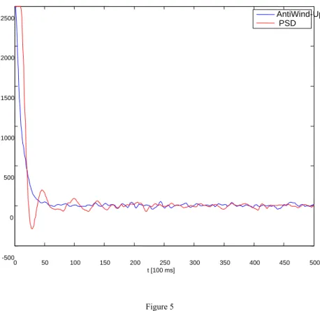
After comparing the time responses of a standard PSD and a PSD with AntiWind- Up it becomes clear that AntiWind-Up is able to regulate the system much better during the start-up and step changes (Figure 5).
Figure 5
The comparison of time responses for standard PSD and PSD with AntiWind-Up technology
0 50 100 150 200 250 300 350 400 450 500
-500 0 500 1000 1500 2000 2500
t [100 ms]
AntiWind-Up PSD
Conclusions
In our thesis we tested different control methods on a real system. We focused mainly on control abilities using the specific interconnection of RT-Linux and software package Comedi.
Because of the successful cooperation of Comedi and Real-Time Linux we showed that the real-time workable solution may be created very simply and inexpensively. All the software used in this thesis was developed under the GNU GPL (General Public License, free software license). Therefore the modification is legal, free and simple thanks to the open-source.
Acknowledgement
This article was written based on diploma project of Matej Dobšovič at Institute of Control and Industrial Informatics in 2007 year.
References
[1] RT-Linux manual, www.fmslabs.com
[2] Comedi Project Refencel, The Control and Measurement Device Interface handbook, http://www.comedi.org/doc/index.html
[3] Ilchmann, A., Ryan, E. P.: Universal λ-Tracking for Nonlinearly- Perturbed Systems in the Presence of Noise, Automatica, Vol. 30, No. 2, pp. 337-346, 1994
[4] Allgöwer, F., Ashman, J. Ilchmann, A.: High-Gain Adaptive λ-Tracking for Nonlinear Systems, Automatica, Vol. 33, No. 5, pp. 881-888, 1997 [5] B. C. Kuo, Automatic Control Systems, 6th ed. Englewood Cliffs, NJ:
Prentice-Hall, 1991
[6] C. C. Hang, K. J. Aström, W. K. Ho, “Refinements of the Ziegler-Nichols Tuning Formula,” Proc. IEE, Pt. D., Vol. 138, pp. 111-118, 1991