DOI: 10.1556/606.2020.15.1.16 Vol. 15, No. 1, pp. 169–176 (2020) www.akademiai.com
TOOLS AND METHODOLOGIES OF 3D MODEL-BASED BUILDING SURVEY
1 Patrik Márk MÁDER*, 2 Dorottya SZILÁGYI, 3 Olivér RÁK
1,3 Breuer Marcel Doctoral School, Department of Engineering Studies Institute of Smart Technology and Engineering, Faculty of Engineering and Information
Technology, Boszorkány u. 2 and János Szentágothai Research Center, Ifjúság u. 20 University of Pécs, H-7624 Pécs, Hungary
e-mail: 1patrik.mader@mik.pte.hu, 3oliver.rak@mik.pte.hu
2 Architectural Engineer (BSc), Faculty of Engineering and Information Technology Boszorkány u. 2, University of Pecs, H-7624 Pécs, Hungary, e-mail: szdo95@gmail.com
Received 19 April 2019; accepted 21 June 2019
Abstract: Information-based modeling technology is supported by advanced information technology solutions in the building industry. The integration of its methodology into construction and design processes is already going on. However, many areas still have development possibilities; for instance, building surveys belong to these fields. Countless survey tools and methodologies endeavor to support and ease the work of professionals in design and construction, yet there is a need for comprehensive collaboration. This could be promoted by creating a direct link between survey tools and architectural design software.
This article demonstrates a tool under development that intends to provide a solution to this issue.
Keywords: Building survey, Programming, Architecture, Information model, Database management, 3D printing
1. Introduction
Architectural surveys are essential elements of building processes. Traditional and modern devices help engineers’ work from the start of the design, throughout construction by monitoring measurements, up to renovation and operation processes.
Commercially available tools are diverse, but generally, these can be categorized based on the used technological solutions. Further grouping - independent of the operating principle - is made possible: by the accuracy of the devices, economic aspects,
*
the speed of on-site surveys, the time required for post-processing, and by the resources and competencies demanded.
Conventional devices (including tape measures, scales, and simple laser rangefinders) are available for non-professionals as well. Due to their ease of use, these are frequently applied and popular, although there are many compromises arising in their practice. Accuracy and economical appropriateness are greatly influenced by the experience and expertise of the surveyor and the architectural design that is being assessed [1]. Adequate software-process of the data obtained this way is also a time- consuming process. Nowadays, these techniques are mostly used for simple distance measuring, for documenting smaller scale building dimensions, and for additional measurements to complement surveys made with other technologies.
In addition to traditional devices, innovative, professionally equipped tools that meet today’s needs are also available. This group includes augmented reality applications that can be accessed through tablets and smartphones, laser rangefinders with wireless connectivity, which are capable of displaying 2D and 3D measurement results in their own software environments, and laser scanners that are used to produce spatial point clouds for the digital representation of reality [1]. In the ‘smart’ world, establishing connectivity among mobile devices is a fundamental requirement. This can be implemented with the help of appliances that are capable of radio frequency communication. These set up the connection directly to portable Information Technology (IT) devices using Bluetooth protocol [2], [3] or Wi-Fi standards [4], [5]. A further requirement is the production of files that are suitable for computer post- production. Like in the case of traditional tools, many disadvantages are to be mentioned in this category as well. Operating these devices requires high expertise, costly machines, mobile and computer software skills [6], high processing time [7], and in most of the cases above average IT hardware capacity.
2. Survey device connected with architectural design software As it was introduced in the previous chapter, the use of simple survey tools is only economical in the case of small scale projects. Taking advantage of the potential in modern technologies requires a high level of expertise and cost investment. These problems propose a demand for a solution that is able to bridge the technological gap.
Applying tools with a simply interpretable user interface makes possible to perform quick and accurate measurements that are easy to work with in 3D post-production. The operation of this device is based on a simplified version of the principle of Terrestrial Laser Scanners (TLS) [8]. After manual laser positioning, an ‘ultra low-density’ point cloud substance is produced by taking multiple point-to-point measurements on each surface. To carry this out, the laser module needs to be moved through the servomotors and the components responsible for their control. Then, with the help of algorithms, the obtained data is transformed into 3D model elements, which later can be identified as room boundary structures.
2.1. Hardware
The device under development is based on the open source Arduino hardware and software environment [9], which is supplemented with various modules, servo- and stepper motors, a wireless unit, sensors, a display, a controller and a laser module. The current design of the hardware prototype is the result of a multi-step process that becomes a complex system by testing the components one by one.
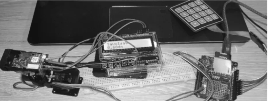
After the operation and the laser module testing, the connection to the control unit has been completed. The first test measure was executed using the Arduino software Integrated Development Environment (IDE) command panel. After the attachment of a display, a battery power supply and coding the program which defines the operation, a real-world test was made possible (Fig. 1).
Fig. 1. Distance measuring test
After making the measuring process possible, the servomotor system responsible for moving was assembled (Fig. 2). Control was initially provided by a 4x4 diaphragm keyboard, but later development scope required a joystick-based control. As soon as the improvement of the wireless connection is accomplished, the external control interfaces could be completely neglected.
Fig. 2. Positioning on two axles, and the test measurement
After distance measurement and movement, the development of data collecting can be declared as the next important milestone. The prototype is currently capable of saving the measured distances and the rotation data to the microSD memory card according to the structure defined during the coding (Fig. 3). Upon completion of the
surveying, the recorded data content can be retrieved for further use by a computer.
After optimizing the wireless connection, the data stored on the memory card will only serve the purpose of security backup. Information will be transmitted directly to the mobile device or computer.
Fig. 3. Dataset of measurements
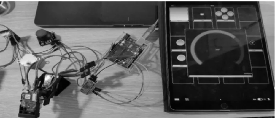
The fourth main step of the development is the establishment of a wireless connection with the purpose to control and transmit the generated data during the surveying. In the current version of the prototype, Bluetooth protocol provides the data flow (Fig. 4), but in the final design, a Wi-Fi standard-based solution is expected to be developed.
Fig. 4. Servomotor control via Bluetooth connection
2.2. Software
The software environment is also necessary to be examined in different aspects. The base of the device and the pillar of the process is the program recorded in the Arduino IDE environment, which defines the operations responsible for moving, measuring, recording and transmitting information (Code 1).
It also records code of numbers and letters that enable control via mobile devices.
These are the framework for processing the commands through a wireless connection, but that alone is not enough for proper operation. There is also a need for mobile device software that makes the connection possible and is able to send the instructions. Hence, the testing of available free and paid software is an integral part of the research, with the aim of testing the programs functionally and gathering experience during their use before developing the new software.
Code 1
if (keypressed != NO_KEY) {
File1 = SD.open("measurementdata.txt", FILE_WRITE);
if (keypressed == '2' || keypressed == '8') { if (File1){
File1.print("Motor1: ");
File1.println(pos);
Serial.print("Motor1: ");
Serial.println(pos);
}
lcd.setCursor(0,0);
lcd.print("Motor1: ");
lcd.setCursor(10,0);
lcd.print(pos);
lcd.setCursor(13,0);
lcd.print((char)223);
}
if (keypressed == '4' || keypressed == '6'){
if (File1){
File1.print("Motor2: ");
File1.println(pos2);
Serial.print("Motor2: ");
Serial.println(pos2);
}
lcd.setCursor(0,1);
lcd.print("Motor2: ");
lcd.setCursor(10,1);
lcd.print(pos2);
lcd.setCursor(13,1);
lcd.print((char)223);
}
After control and measurements, the next step in software solutions is to interpret and transform data that is generated during the survey process. The data recorded and stored without processing constitute only an incomprehensible set of information for architectural design software. In order to support the software data import, a transformation is needed, which is currently implemented in an automated way of using a complex table (Table I). The table automatically calculates the coordinate values required for 3D model elements (e.g. walls, slabs) from the scanned data, and then classifies them according to the measurement logic.
Table I
Segment from coordinate-calculations table
Nr distance
last MOTOR1 angle ("α")
last MOTOR2 angle ("β")
Z X Y
1 1.104 28 83 0.518297 0.967508 0.11879508
2 2.144 41 66 1.406591 1.478205 0.65813948
3 1.674 0 66 0 1.529275 0.68087714
4 2.861 21 49 1.025291 2.015809 1.75231635
5 3.397 30 23 1.6985 1.149487 2.70802246
6 3.912 1 6 0.068274 0.408853 3.8899771
7 3.623 -8 -29 -0.50422 -1.73937 3.13790917
8 3.588 -10 -36 -0.62305 -2.07693 2.85865364
9 3.651 -14 -32 -0.88326 -1.87727 3.00425253
10 1.933 13 -67 0.43483 -1.73373 0.73592541
11 1.109 -21 -86 -0.39743 -1.03282 0.07222172
12 1.291 -21 -78 -0.46265 -1.17891 0.25058605
13 2.229 62 -54 1.96809 -0.8466 0.61508912
14 2.158 62 8 1.905401 0.140999 1.00326002
15 2.144 -23 8 -0.83773 0.274667 1.95435583
16 1.103 -45 -44 -0.77994 -0.54179 0.56104101
The final step of the methodology is to produce the digital twin of the real space on which the survey is based. This is carried out by using the calculated coordinate values and the developed algorithm that processes them. The software generates the boundary structures of the surveyed room using the grouped data of the table. This can already be interpreted by architectural design software, like defining elements that as wall and slab structures.
Currently, the final result is produced in Autodesk Revit environment using the Dynamo Add-In (Fig. 5), but the development of the connection between the survey tool, Graphisoft ArchiCAD and Grasshopper is already going on.
Fig. 5. Algorithm and 3D model
2.3. Appearance
The preparation of the prototype is not only made up of the assembly of the electronics and programming the software. Planning the design and the exterior shape is also an integral part of the research. Creating this shell is a design task that requires the production of many experimental versions.
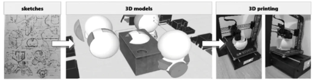
A fundamental aspect is to come up with a design that is easy-to-carry, compact, and has a modern appearance. Several preliminary versions have been designed and produced, but further optimization is needed for the perfect performance (Fig. 6).
Form and frame design are carried out via 3D modeling software, thus 3D printing happens to be the easiest and most economical way to produce the shell. Prototypes are made from PLA material using a 3D printer with FDM technology.
Fig. 6. Design and manufacturing process
3. Conclusion
A highly functional yet simple device paired with the suitable survey methodology can provide a great alternative to professional building survey. The results so far are considered to be positive, hence intending for the progression of the research and development. The work is to be continued by creating collaboration with additional design software based on the conclusions of the described research part to this point.
Technical and functional development, optimization, appearance design, the customization of the control unit, and the improvement of methodology-based services are also in the future scope. Detailed documentation of the results will follow the development phases in the form of scientific articles.
4. Acknowledgments
The research and the article were financed and supported by ‘Ministry of Human Capacities, Human Resource Support Manager’ with the identification ‘NTP-NFTÖ- 18’, titled ‘National Young Talent Scholarship’.
Open Access statement
This is an open-access article distributed under the terms of the Creative Commons Attribution 4.0 International License (https://creativecommons.org/licenses/by/4.0/), which permits unrestricted use, distribution, and reproduction in any medium, provided the original author and source are credited, a link to the CC License is provided, and changes - if any - are indicated. (SID_1)
References
[1] Kari Sz. Building survey, point cloud, BIM, Modern building survey methods and BIM relationship, (in Hungarian) http://lechnerkozpont.hu/data/sites/default/files/pic/article/
jovot-tanulni-jottek/prezentacio/kari-szabolcs-epuletfelmeres-pontfelho-bim.pdf, (last visited 3 February 2019).
[2] What is Bluetooth? (in Hungarian) http://www.iminet.hu/cikk/mi-is-az-a-bluetooth.html, (last visited 15 February 2019).
[3] Bluetooth technology, https://www.bluetooth.com/bluetooth-technology, (last visited 15 February 2019).
[4] The WiFi (in Hungarian) https://wifipedia.hu/wifi, (last visited 10 March 2019).
[5] Sourangsu B., Rahul S. C. On IEEE 802.11: Wireless LAN technology, International Journal of Mobile Network Communications & Telematics, Vol. 3, No. 4, 2013, pp. 6-12.
[6] Honti R., Erdélyi J., Kopáčik A. Plane segmentation from point clouds, Pollack Periodica, Vol. 13, No. 2, 2018, pp. 159–171.
[7] Fehér K., Halmos B. Problems of surveying profile shapes of gothic architectural fragments, Pollack Periodica, Vol. 13, No. 1, 2018, pp. 217–224.
[8] Réhányi N. Terrestrial laser scanner accuracy testing (in Hungarian) 2010/2011 TDK study, Budapest, 2010.
[9] What is Arduino? https://www.arduino.cc/en/guide/introduction, (last visited 10 June 2019).