OF INDUSTRY AND CHEMISTRY VESZPRÉM
Vol. 42(1) pp. 51–56 (2014)
DEVELOPMENT OF A REACTION STRUCTURE IDENTIFICATION ALGORITHM
JÁNOS KONTOS,1!LÁSZLÓ RICHÁRD TÓTH,2 AND TAMÁS VARGA2
1 Department of Physical Chemistry, University of Pannonia, Egyetem St. 10, Veszprém, H-8200, HUNGARY
2 Department of Process Engineering, University of Pannonia, Egyetem St. 10, Veszprém, H-8200, HUNGARY
!E-mail: kontosjan@gmail.com
The most important step in the design procedure of a chemical reactor is the understanding the chemical reaction network (CRN), which will take place in that reactor. The structure of a CRN as representation of the reaction mechanism contains all the elementary reaction steps that are required to convert the reagents into products. The aim of the reaction mechanism analysis is the identification of the route how the system goes from its initial to the end state. In order to do this, a lot of knowledge is required about chemistry supplemented with some analytical measurements. In this work, we focus on the development of an algorithm, which requires a few data inputs to reveal all the reaction steps that are important in the reactor design point of view. It is trivial that the structure of a dynamic system cannot be determined without the identification of the model parameters that belong to that structure. Hence, the algorithm reported here can be used to obtain the parameters of the reaction rate equations for each identified chemical reaction. First, the structure is identified followed by its parameters. In this study the processed data are obtained by a CRN generator, which is applied to generate random CRNs based on some specified parameters to reach maximal reaction order. Concentration profiles, which characterize each CRN at a specific reaction rate constants combination, are obtained as a result of simulations based on the randomly generated CRNs. The developed algorithm for reaction mechanism identification is based on a modified type of linear least-squares method (LLSM) in which the searching variables must be higher than zero, since the reaction rate constants cannot have negative values. The developed algorithm is tested in different cases to check the applicability of LLSM in reaction structure identification procedure and the obtained results show that with some further improvements the proposed algorithm can be applied solving more complex identification tasks.
Keywords: chemical reaction network, structure identification, non-negative least-squares method, CRN generator
Introduction
One of the most important tasks during the design procedure of any chemical technology is the engineering design of the conversion subsystem and to ensure the optimal and safe operation. Hence, before starting the design of a technology phenomena with impact on the dynamic behaviour of the subsystem must be identified. The most crucial part of the conversion subsystem is the chemical reactor in which we try to control the processes that was identified on the basis of laboratory experiments. In this work we proposed a method to support the identification of the individual reaction steps and their rates in a chemical reaction network (CRN).
Numerous literature examples can be found that describe different methodologies to generate the structure of CRNs, as representations for reaction mechanisms [1, 2]. The reaction mechanism of a reaction system represents all the elementary reaction steps, which are required to convert the reagents into products. Hence, the aim of reaction mechanism identification is the determination of the intermediate steps, which take the starting materials to the final products. Trivially, it is challenging to follow and model
the movements of all the molecules in a system in full detail. However, we can describe a reaction system on the basis of the cumulative effects of great number of molecules in specific states. Such specific states are the formation of stable intermediates.
The intermediates are chemical species produced in the elementary reaction steps. Often, it is possible to detect them by experimental methods. The produced amount of these intermediates is sometimes very low and they react very fast to produce another intermediate or final product. Hence, the identification of the latter components and the measurement of their concentrations can be challenging. Most of the reactions take place through multiple intermediate steps. These scenarios are called multi-step reactions. In a single reaction step, the sign of stoichiometric coefficients represent that a given molecule is a reagent (-) or product (+), and the absolute value of these coefficients give how many moles are consumed/formed.
The transient states of a reaction system and the intermediates can be investigated with two kinds of methods on the basis of whether a priori knowledge of reaction kinetics is available or not [3]. The foundation of the reaction mechanism analysis is the precise identification of all intermediates and their
concentration. With the lack of this information the stoichiometry of the reaction cannot be revealed reliably. The nature and the amount of the products can contain as much information as a well-qualified chemist requires identifying the reaction mechanism of an unknown reaction system. The proposed algorithm can support this process in case we have lack of experience in the identification of the structure of a CRN and parameters of kinetic expressions, which describe the rate of the reaction steps considered in the CRN.
The essence of the parameter identification process is the solution of a constrained minimization problem in which the objective function can be the sum of squared error between the measured and the calculated component concentration profiles. The searching variables are the unknown parameters in the kinetic expressions (i.e. pre-exponential factor, activation energy, reaction order).
The role of the structure identification is the definition of correlated variables and their mathematical formalization. In our case, the identification means the selection of reaction steps that can take place in the reactor. The identification tasks can be solved by the application of linear least-squares method (LLSM) [4].
The main challenges using this method are the definition of the correct initial conditions for the applied searching algorithm and the speed up of the identification procedure.
One of the most important simultaneous methods is the incremental approach, which applies a hierarchical modelling methodology to decompose the complex
identification problem into simpler sub-problems [5].
The method applies target factor analysis to identify the suitable structure of the unknown CRN. This method has been successfully applied in reaction mechanism identification process in a multi-phase system based on concentration and calorimetric measurements [6].
Correlation metric method was developed to analyse the strength of the connections between the components in the system, which is based on the qualitative analysis of the measured data [7]. Qualitative trend analysis was also applied in reaction mechanism identification algorithms to divide the entire experimental time into shorter periods in which the correlations are analysed between the concentrations of components [8].
In this work, our aim is to develop a simple, but reliable method for structure identification of CRNs, which need as few data as possible. In our case the input of the algorithm is only the list of components and concentration profiles, which are the result of the simulation based on randomly generated CRNs. These CRNs were generated based on user specified parameters, such as maximal reaction order. On the basis of the randomly generated CRNs, the concentration profiles for each CRN at a specific reaction rate constants combination are determined. The algorithm developed for reaction mechanism identification is based on a modified LLSM method, in which the searching variables must be higher than zero, since the reaction rate constants cannot have negative values.
Development of Simulation Methods
Since our aim is to develop a generally applicable algorithm to support the identification process of CRNs with unknown structure, we developed a CRN generator, which can be applied to randomly generate CRNs based on some structural parameters, such as the maximum number of components or reactions in CRN.
There are many examples in literature for developing a CRN generator that analyses the affinity of molecules taking part in reactions [9], applies mixed integer programming to build up reaction networks [10], or using group contribution method to generate the structure of the CRN and the kinetic parameters of the reaction steps in that network [11].
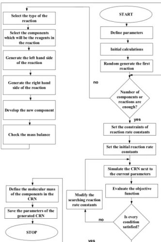
In this work we developed a simple CRN generator that randomly generates a CRN from randomly generated components. In this generator, we define probabilities in situations for building different kinds of CRNs. For example, if we would like to have more decomposition reactions in the CRN then the probability of this type of reaction is increased. The scheme of the developed CRN generator can be seen in Fig.1.
The first step of the algorithm of the CRN generator is the definition of the parameters of the desired CRN, such as the probabilities of the different types of reactions. In this step the maximal number of building block types in a component and the maximal number of specific building blocks in a component are defined.
Figure 1: The scheme of the proposed CRN generator
The next step is the development of the first reaction step in which we define a new component next to the components that are already in the component list. The stoichiometric coefficients of the reaction are randomly generated based on the user-defined parameters. The composition and the chemical formula of the added component are determined based on the material balance of the reaction. With the first reaction step, it is checked whether the numbers of components and reactions in the generated CRN are enough.
If the user defined value of these parameters are higher than the current values the CRN generator starts to build a new reaction with selecting the reaction type, the components. Based on the CRN parameters it randomly generates stoichiometric factors for that new reaction and checks the material balance. Components that are involved in more reactions have a smaller chance to be chosen for the next new reaction building iteration.
If there are enough components or reactions in the generated CRN, the algorithm steps to the next phase in which it randomly generates the reaction kinetic constants for reactions in the CRN. In this phase, the algorithm randomly generate kinetic parameters, while maintaining the same order of magnitude of the reaction rates, to make it harder to find out the structure of the generated CRN. Particle swarm optimization method has been applied to solve this constrained optimization problem, where the objective function is defined as the difference of the integral of reaction rates over the time [12].
General Reactor Model
The kinetic experiments are usually performed in a tempered flask that can be modelled as an isothermal batch reactor. All the reagents are added to the unit with or without catalyst and samples are taken from the reaction mixture in specific times. As mentioned earlier the simplest case is considered as we have only concentration measurements from a batch reactor.
However, the developed algorithm can be improved and the processability of data can be widened with the application of mathematical models of other reactor types.
Hence, at this point of the development of the proposed algorithm, we consider that the unit in which the kinetic experiments are performed is a well-mixed, isothermal batch reactor. The model of a batch reactor should be developed first to contain component mass balance equations. Applying the well-mixed assumption the component mass balances can be simplified and we obtain the equations:
{
A;B;C;...}
,i dt R
dc
i = i = (1)
where I identifies the components in the system in which we have Nc components; ci is the concentration of the ith component [mol m-3]; Ri is the component source of the ith component [mol m-3 s-1], which can be calculated as:
Ri= υji⋅rj
j=1 NR
∑ , (2)
where j identifies the reaction in the system; NR gives the number of reactions considered; νji is the stoichiometric coefficient of the ith component in the jth reaction; rj is the reaction rate of the jth reaction [mol m-
3 s-1], which is calculated with following expression:
rj=kj cinji
i= A;B;C;...{ }
∏
, (3)where nji denotes the order of ith component in jth reaction [1], kj is the reaction rate constant of the jth reaction [the unit is dependent on the order of the
reaction, [mol1-n
m3n-1 s-1], where n is the summarized reaction order in jth reaction:
n= nji
i= A;B;C;...{ }
∑
. (4)This summarized reaction order is equal to the absolute value of the stoichiometric coefficient of the ith component in the jth reaction, if the given component is a reagent in a given reaction, otherwise it is 0. The developed general reactor model has been implemented in MATLAB.
Proposed Algorithm for Structure Identification of CRN Our primary aim is to develop an algorithm, which can be efficiently applied in reaction mechanism identification tasks on the basis of concentration profiles. In this phase, we considered that the concentration profiles are known for all the components in the system. It is a simplification with respect of practical problems; however, in this work we aim to evaluate if a simple method of LLSM is suitable for a complex task.
LLSM is based on the minimization of a special model error, which is based on comparing the measured to the calculated time series. In our case, the time series are the numerical derivatives of the concentration profiles. Based on the measured concentration profiles the change in concentration during two sampling steps can be calculated as a numerical derivative with respect to length of that time step. If we have Nk samples, the difference in kth sample can be defined as follows:
Δcˆi
Δt
( )
k =cˆi( )
k −cˆi(
k−1)
, (5)where k is the current sample; Δcˆi is the difference of the measured concentration of ith component in between k and k-1 sampling steps; Δt is the time difference between k and k-1 sampling steps.
If we calculate this difference for all the components and in every sampling steps we get a matrix which has k-1 rows and as many columns as many components we assume in the system. Based on the calculated concentration profiles another matrix can be built with the calculated variables. In our case the sum of the
squared differences between these two matrices is defined as the model error, which should be minimized during the identification process:
E= Δcˆi
Δt
( )
k −ΔcΔti( )
k#
$% &
'(
2 k=1
Nk
∑
i= A;B;C;...{ }
∑
, (6)where E is the calculated model error, which is basically the difference of the measured and calculated component sources defined with Eq.(2); Δci is the calculated changes in concentrations of ith component from Eq.(1), but the steps is equal with the sample times of measurement.
To make it easier to follow the process we define Eq.(6) using vectors instead of sums:
E=#Δ___cˆ− Δc___
$% &
'(
T
Δcˆ
___
− Δc___
#
$% &
'(, (7)
where the length of vectors are Nc(Nk-1) (i.e. the change in concentrations of components should be calculated in every sample time except in the initial phase) and defined with the following structures:
Δcˆ
___
=
ΔcˆA
( )
1 ΔcˆB( )
1! ΔcˆA
( )
2 ΔcˆB( )
2! ΔcˆA
( )
k ΔcˆB( )
k!
"
#
$
$
$$
$
$
$
$
$$
$
$
$
$
%
&
' ' '' ' ' ' ' '' ' ' ' '
, Δc___=
ΔcA
( )
1 ΔcB( )
1! ΔcA
( )
2 ΔcB( )
2! ΔcA
( )
k ΔcB( )
k!
"
#
$
$
$$
$
$
$
$
$$
$
$
$
$
%
&
' ' '' ' ' ' ' '' ' ' ' '
. (8)
The task in LLSM is the minimization of the model error defined in Eq.(7) by manipulating the model parameters, such as the reaction rate constants of all the possible reaction steps, which are the building blocks of the unknown CRNs. Hence, to use LLSM in reaction mechanism identification process first we need to collect all the possible reaction steps, which can take place in the system based on the defined component list.
To get the necessary reaction steps, we generate all the possible combination of reactions, which satisfy the material balances. A given reaction step has to be further processed, since some reaction steps can be produced from each other with linear combinations.
Thus, only the independent reactions should be kept in the reaction set. The resulted reaction set is represented in a matrix (i.e. in stoichiometric matrix):
=
υRS ,
B A
B A
B A
!!
!
"
#
$$
$
%
&
υ υ
υ υ
!
"
"
#
#
"
#
2 2
1 1
2
1 (9)
which has the same number of rows and columns as the number independent reactions and components are considered in the system, respectively.
After the possible reaction steps have been automatically collected, all the reaction steps of the set are considered as the part of the unknown CRNs. Based on the reaction set the mathematical model of the system is automatically generated based on Eqs.(1)-(3).
The unknown parameters in this model are the reaction rate constants for all reactions in the reaction set.
The calculated concentration differences in Eq.(7) can be obtained using Eq.(10) on the basis of the general reactor model (Eqs.(1-3)):
, c k
___c υ
=
Δ (10)
where c denotes a special matrix in which a diagonal matrix is repeated from sample time to sample time and in the diagonal matrices we calculate the concentration product term in Eq.(3) in every sample time. The following general matrix shows the structure of the resulting diagonal matrix in this step if we have NR reactions in the reaction set:
c=
ci( )0
( )n1i
i={A;B;C;...}
∏ 0 !
0 (ci( )0)n2i
i={A;B;C;...}
∏ !
" " #
ci( )1
( )n1i
i={A;B;C;...}
∏ 0 !
0 (ci( )1)n2i
i={A;B;C;...}
∏ !
" " #
ci(k−1)
( )n1i
i={A;B;C;...}
∏ 0 !
0 (ci(k−1))n2i
i={A;B;C;...}
∏ !
" " #
#
$
%
%
%%
%
%
%
%
%
%%
%
%
%
%
%
%
%%
%
%
%
%
%
&
' ( ( (( ( ( ( ( ( (( ( ( ( ( ( ( (( ( ( ( ( (
(11)
υ denotes a special matrix in which the stoichiometric matrix representing the reaction set (Eq.(9)) is repeated as many times as the sample times minus one:
= υ
υRS
υRS
!
!
"
##
##
#
$
%
&
&
&
&
&
(12)
kindicates reaction rate constant vector for all the reactions in the reaction set.
By applying LLSM, the structure of the unknown CRN can be identified since the reaction rate constants that can be the part of the unknown CRN will have different values than zero at the end of the identification process and all the other reactions in reaction set get zero value. Based on Eqs.(7) and (10) we can solve the minimization problem and the following expression is the result for the calculation of reaction rate constants for all reactions in the generated reaction set:
' ___
' ' '
' c c c cˆ
k ## ×Δ
$
%
&&
'
( # ×
$
& % '( υ
* ×
* + , -
- . /
##$
%
&&
'
( # ×
$
& % '( υ
## ×
$
%
&&
'
( # ×
$
& % '( υ
=
−1
(13)
Reactions with zero reaction rate constants indicate that they cannot be part of the unknown CRN. This means that at the end of the identification process we get the reaction rate constants as well, next to the structure of the CRN.
Results and Discussion
Since we do not have measurements from a real system in this work the developed CRN generator has been applied to randomly generate some CRNs. Table 1 shows two reaction steps in the unknown CRN. We have defined five components (A-E) in the system. A and B components are reagents in the first reaction step (R01), in which C and D components are produced.
However, in the second reaction (R02) only E is consumed while 2 moles of A and 1 mole of D are produced. The last column of Table 1 shows the exact values of reaction rate constants. The unit of reaction rate constants can be determined for the jth reaction based on the sum of the reaction orders of each component in that reaction:
mol m3
!
"
# $
%&
1− nji
i={A;B;C;...}
∑
!
"
#
#
$
%
&
& ⋅1
s (14)
Table 2 shows the five components (A-E) that are built from nine (a-j) building elements. These building elements can be imagined as atoms or groups. The numbers in the matrix represents the stoichiometric coefficients of composition. The last row shows a fictitious molecular mass of the components in the system.
Based on the molecular mass and the number of building elements in the components all the independent reaction steps were generated as shown in Table 3. The 22 possible reaction steps can be found for the five components from Table 2. The unknown reaction mechanism should be built from these reaction steps. In Table 1 we saw that we need only two of these steps and as it can be seen in the last column of Table 3 with the proposed algorithm we can find these two reactions of RS01 and RS16. However, the algorithm identifies a third possible reaction step, RS13, which can be the part of the unknown CRN. As can be seen in the last column of Table 3, the reaction rate constant corresponding to this reaction step is very low. This means RS13 should not be considered as the part of the unknown CRN.
After the above simple task, we tested our method in nine other cases. We defined a quantitative measure to check the correctness of the identified kinetic parameters as the mean average difference between the known and the identified reaction rate constants:
MAE= 1 Ndr
kˆl−kl
l=1 Ndr
∑
(15)where Ndr is the number of reactions in unknown CRN; l identifies the current reaction rate constant;kˆis the reaction rate constant value what we are looking for, such as the last column in Table 1 for CRN01.
Table 4 presents the number of reaction steps in the unknown CRN (Ndr), the number of components (Nc) in the system, the number of the possible reaction steps (Nr) as a representation of the size of the reaction set, if the algorithm can find the perfect reaction steps or not, and MAE values when available from Eq.(15).
Table 1: A randomly generated CRN with CRN generator
A B C D E k [-]
R01 -1 -1 1 1 0 1.5590
R02 2 0 0 1 -1 1.0184
Table 2: The generated compound matrix
A B C D E
a 9 0 1 8 26
b 10 0 8 2 22
c 7 1 1 7 21
d 2 10 7 5 9
e 4 12 13 3 11
f 12 0 1 11 35
g 8 0 6 2 18
h 11 5 7 9 31
j 6 1 3 4 16
M [mass mol-1] 359 195 252 302 1020 Table 3: The resulted reaction step matrix with the identified
reaction rate constant
RS ID A B C D E k [-]
RS01 -1 -1 1 1 0 1.626 RS02 -3 -1 1 0 1 0 RS03 -2 0 0 -1 1 0 RS04 -2 6 3 -4 0 0 RS05 -3 5 4 -3 0 0 RS06 -4 4 5 -2 0 0 RS07 -5 3 6 -1 0 0 RS08 0 4 5 0 -2 0 RS09 -3 3 6 0 -1 0 RS10 5 -3 -6 1 0 0 RS11 3 -3 -6 0 1 0 RS12 4 -4 -5 2 0 0 RS13 0 -4 -5 0 2 0.004 RS14 3 -5 -4 3 0 0 RS15 2 -6 -3 4 0 0 RS16 0 -6 -3 3 1 0 RS17 2 0 0 1 -1 1.051 RS18 0 -2 2 3 -1 0 RS19 1 1 -1 -1 0 0 RS20 0 2 -2 -3 1 0 RS21 3 1 -1 0 -1 0 RS22 0 6 3 -3 -1 0
Based on the results in Table 4 it can be seen that the proposed algorithm has some limitations in this phase.
However, if the size of the reaction set is relatively small it gives very good agreement with the desired parameters. This means that we should improve this method to make possible the analysis of more complex problems with it. If the algorithm cannot find the perfect match for the unknown CRN a ratio is given which shows how many of the reaction steps are correctly identified from the unknown mechanism.
Conclusions
The structure of a CRN represents all the elementary reaction steps that are required to convert the reagents into products. Hence, the aim of reaction mechanism identification is to discover the intermediate steps, which connect starting materials with the final product.
The proposed algorithm can support this process even in the case, when we lack knowledge about the reaction mechanism and/or kinetic parameters.
The applied structure identification method is based on linear least-square method. The measured and calculated concentration profiles are compared and the difference between these profiles is minimized during the identification process. The proposed algorithm for reaction mechanism identification was implemented in MATLAB.
The results of initial testing showed promising results for this simple method being applicable for a complex task; however, the proposed algorithm should be improved toward processing reaction sets. The given implementation of the algorithm for batch reactor models can be easily extended to other reactor models, which enables to employ our method to realistic problems from chemical industry.
Acknowledgements
This research was supported by the European Union and the State of Hungary, co-financed by the European Social Fund in the framework of TÁMOP 4.2.4.A/2-11- 1-2012-0001 ‘National Excellence Program’.
REFERENCES
[1] DELVIN S.:Organic Reaction Mechanism, Sarup &
Sons, New Delhi, 2002
[2] GROSSMAN R.B.:The Art of Writing Reasonable Organic Reaction Mechanisms, Springer, New York, 2003
[3] FRIESS S.L.,LEWIS E.S.:Investigation of Rates and Mechanisms of Reactions, John Wiley & Sons, New York, 1963
[4] WALTER E.: Identification of Parametric Models from Experimental Data, Springer-Verlag, Berlin 1997
[5] BENDEL M.L., BONVIN D., MARQUARDT W.:
Incremental identification of kinetic models for homogeneous reaction systems, Chem. Eng. Sci., 2006, 61, 5404–5420
[6] SRINIVASAN S., BILLETER J., BONVIN D.: Extent- based incremental identification of reaction systems using concentration and calorimetric measurements, Chem. Eng. J., 2012, 207–208, 785–793
[7] SAMOILOV M., ARKIN A., ROSS J.: On the deduction of chemical reaction pathways from measurements of time series of concentrations, Chaos, 2001, 11, 108–114
[8] VARGA T.: Qualitative Analysis Based Reaction Mechanism Identification, Chem. Eng. Trans., 2013, 35, 769–774
[9] RATKIEWICZ A., TRUONG T.N.: Application of Chemical Graph Theory for Automated Mechanism Generation, J. Chem. Inf. Comput.
Sci., 2003, 43, 36–44
[10] FIRST E.L., GOUNARIS C.E., FLOUDA C.A.S: Stereochemically Consistent Reaction Mapping and Identification of Multiple Reaction Mechanisms through Integer Linear Optimization, J. Chem. Inf. Model, 2012, 52, 84–92
[11] WEST R.H.,ALLEN J.W.,GREEN W.H.:Automatic Reaction Mechanism Generation with Group Additive Kinetics, ChemInform., 2012, 43, 36–258 [12] KENNEDY J., EBERHART R.: Particle swarm
optimization in Neural Networks, Proc. IEEE International Conference on Neural Networks, Perth, Australia, 1995, 4, 1942–1948
Table 4: Testing the developed algorithm in case of 10 CRNs CRN ID Ndr Nc Nr match MAE [-]
CRN01 2 5 22 y 0.0498 CRN02 3 5 40 n (1/3) - CRN03 3 5 11 y 0.0983 CRN04 2 5 17 y 0.0268 CRN05 4 5 26 y 0.1197 CRN06 2 5 13 y 0.0146 CRN07 3 5 10 y 0.0216 CRN08 4 5 119 n (0/4) - CRN09 3 5 85 n (0/3) - CRN10 4 5 19 y 0.0748

![Table 4: Testing the developed algorithm in case of 10 CRNs CRN ID N dr N c N r match MAE [-] CRN01 2 5 22 y 0.0498 CRN02 3 5 40 n (1/3) - CRN03 3 5 11 y 0.0983 CRN04 2 5 17 y 0.0268 CRN05 4 5 26 y 0.1197 CRN06 2 5 13](https://thumb-eu.123doks.com/thumbv2/9dokorg/1112269.77632/6.892.78.412.118.311/table-testing-developed-algorithm-case-crns-crn-match.webp)
