An International Journal for Engineering and Information Sciences DOI: 10.1556/606.2020.15.1.12 Vol. 15, No. 1, pp. 124–135 (2020) www.akademiai.com
STATE SPACE MODELING THEORY OF INDUCTION MACHINES
1 Zoltán NÉMETH*, 2 Miklós KUCZMANN
1,2 Department of Automation, Széchenyi István University, Egyetem tér 1 H-9026 Győr, Hungary, e-mail: 1nemeth.zoltan@sze.hu, 2kuczmann@sze.hu
Received 31 January 2019; accepted 17 June 2019
Abstract: The paper discusses the theoretical background of the state space modeling of induction machines. The main goal is to present the necessary equations of the induction machine and the topic of the state space modeling. Although the induction machine is a highly non-linear system, LPV/qLPV model can be formulated from these equations.
Keywords: State space model, Induction machine, Clark and Park transformation
1. Introduction
The objective of this work is to discuss the theory of state space modeling of induction machines including the necessary equations and theoretical background.
The increasing penetration of electrical machines in all parts of the world can be observed, but the available models are still containing a lot of simplifications.
Regardless of whether the induction machine is one of the oldest kinds of electrical machines, it still has a lot of potential using. Despite of the large amount of knowledge, even the newest models do not contain the frequency dependency, and only a few has a state estimator for the rotor temperature [1]-[5].
The integration of the temperature and frequency dependency into the state space models requires the basic knowledge of the behavior. The future work is going to be the extension of the basic model introduced in this paper with the above-mentioned
* Corresponding Author
shortcomings. The results achieved here will be used in the future in the field of Linear Parameter Varying (LPV) modeling [6]-[8].
2. Induction motor model
This section presents the dynamic model of the squirrel cage induction machines.
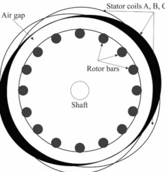
The cross-section area can be seen in Fig. 1. The stator coil windings (A, B, C) are parallel to the rotor bars and displaced by 120 degrees. These coils are fed by sinusoidal current to obtain rotating magnetic field [9] and [10].
Fig. 1. Cross section of squirrel cage induction motor
As it has been mentioned before, this work is mostly going to be a summary of the state space modeling of induction machines. The model discussed here has the following assumptions [11], [12]:
• the motor is symmetrical, the three phases have the same parameters;
• the width of the air gap is constant, denoted by h;
• only the fundamental harmonic has been considered;
• the stator windings are star connected;
• the permeability of the iron parts is infinite;
• the coil resistance is constant;
• iron losses, end-effects, slotting effects are neglected;
• magnetic saturation and eddy currents are also neglected.
One more simplification is needed, where the rotor currents are considered as three- phase system, the same as the stator windings.
2.1. Electro-magnetic model
The electro-magnetic model describes the torque acting in the rotor as a function of the stator currents = ( ), = ( ) and = ( ). In this model, the capital letters in subscript (ABC) are for the stator and the small ones (abc) for the rotor.
Having an isolated neutral point
( ) + ( ) + ( ) = 0 (1)
is valid at any time. The magneto-motive force excited by the stator currents can be calculated as [11]
( , ) = cos( ) + cos − + cos − , (2)
where is the angle of the stator current, and Ns is the number of turns of the stator coils. The force fr produced by the rotor can be formulated similarly as (2), but each cosine function have been shifted with the electrical angle of the rotor , and a fictive number for the rotor coil windings has been used.
Flux density can be calculated for the stator and rotor as well from fs and fr, and the part of the flux density B on the rotor surface due to the stator currents is
( , ) = !" ( , ) + ( , )#, (3)
where $% is the permeability of the vacuum and " is the coupling factor. The electro- magnetic torque Te can be calculated as [11]
&'( ) = ( !−)*% ( , )+ ( , )#d , (4)
where ar is the current distribution on the rotor surface, r is the radius and l is the length of the rotor. The flux linkage in stator coil A is [11]
- ( ) =. (3 // cos/ (03 /01 / !−)* ( , )#d d/. (5) The same equation can be found for the rotor coils:
-4( ) =. (3 // cos/ 5(03 / 1801671899!−)* ( , )#d :d/. (6) Eqs. (5) and (6) can be formulated for the phases B and C as well, both in stator and rotor side. The input to neutral voltage in stator coils is given as [11]
; ( ) = < ( ) +=>=- ( ), (7) where Rs is the resistance of the stator windings. The same equation for rotor coil is
0 = < 4( ) +=>=-4( ), (8)
where Rr is the rated rotor resistance, it is given in the datasheets. These equations can be simplified by using complex space vector notation and the shifting vector ? = eA / . The over line notation is for complex values in the following equations. The stator voltage and current are defined as [11]
;B ( ) = !; ( ) + ?; ( ) + ? ; ( )#, (9)
( ) = ! ( ) + ? ( ) + ? ( )#. (10)
These equations are valid for peak voltage and current. The rotor current can be formulated as
( ) = ! 4( ) + ? C( ) + ? D( )#. (11)
The stator and rotor flux linkages can be defined by space vectors as
-E ( ) = !- ( ) + ?- ( ) + ? - ( )#, (12)
-E ( ) = !-4( ) + ?-C( ) + ? -D( )#. (13) Inserting (5) and the other phase equations (B and C) into (12) resulting in
-E ( ) = F + FG HA89(>), (14)
where Ls is the stator inductance and Lm is the mutual inductance. Similar equation can be obtained for the rotor:
-E ( ) = F + FG H3A89(>), (15)
where Lr is the rotor inductance. Using the space vector notation on (7) and inserting it into (14) gives
; ( ) = < ( ) + F I>I ( ) + FGI>I HA89(>). (16) Similar equation can be written for the rotor
0 = < ( ) + F =>= ( ) + FG=>= H3A89(>). (17) The electro-magnetic torque takes the following form [11]:
&'( ) = JFG Im M ( )! ( )HA89(>)#∗O, (18) where p is the number of pole pairs.
3. Complex state space model
The induction motor model can be expressed in stator or in rotor fixed coordinate system. First, stator fixed coordinate system has been introduced, so the rotor current phase in (17) must be shifted with i.e.
0 = (< − jQ ( )) ( ) + F (=>=− jQ ( )) ( ) + FG(=>= − jQ ( )) . (19) The mechanical model takes the following form according to [13]:
QR ( ) = JQRG'D ( ) =.S(&'( ) − &T( ) − UQG'D ), (20) where QVWXY is the mechanical rotating speed, ωr is the electrical rotating speed of the rotor, J is the collective moment of inertia of the rotor, TL is the actual load and D is the viscous friction coefficient. The value of D is taken from [13]. The basic state space model can be obtained from (17), (19) and (20) [12]:
ZRD = [ DZ D+ \D;, ZD = ] ^, (21)
[D = _
`aT91ATb7c9 T7b3T9Ta
3`aTb1AT9Tbc9 Tb73T9Ta 3`aTb3ATaTbc9
Tb73T9Ta
`9Ta3ATaT9c9 Tb73T9Ta
d, \D= _
3T9 Tb73T9Ta
Tb Tb73T9Ta
d. (22)
3.1. State transformation
As the literature says [12], [14], for control purposes it is often desirable to work with different state vector then xsc, it can be obtained by multiplication of the transformation matrix e = ]1 0
1 TTb9^ as
ZD>= eZ D, [D>= e[ De3., \D>= e\D. (23)
It is important to note that the magnetizing current im has the same angle as the rotor flux. After performing the matrix multiplications in (23), the complex state space model takes the following form:
ZR D>= [D>Z D>+ \D>;, (24)
Z D>= ]
G^, (25)
[ D>= _
`9T7b1`aT97 T9(T7b3T9Ta)
3`aTb1AT9Tbc9 T9(Tb73T9Ta)
`9
T9 −jQ −`T99 d, \D>= ]Tb73T3T99Ta
0 ^, (26)
and
&'( ) = JTT7b9Im M G∗
O. (27)
4. Real state space model
The model described in Section 3 has some disadvantage with the complex values.
To obtain a model with only real values, matrices, the complex space vector must split into real and imaginary parts as
; = ;g+ j;h, (28)
= g+ j h, (29)
G= Gg+ jGh. (30)
The real state space model can be obtained by [ + j[i → k[ −[i
[i [ l, (31)
Z + jZi → mZ
Zin. (32)
Implementing (31) and (32) into (25), (26), (27) it results in a real state space model of the induction machines:
ZR = [ Z + \ o , (33)
Z = p
g Gg
h Gh
q, o = m;g
;hn, (34)
[ =
rs ss ss
tT`99(TTb7b71`3T9aTTa97) T9(T3`b793TTb79Ta)
`9
T9 −`T99
0 −T9(TTb7c9
b73T9Ta)
0 −Q
0 T9(TTb7c9
b73T9Ta)
0 Q
`9Tb71`aT97 T9(Tb73T9Ta)
3`9T7b T9(T7b3T9Ta)
`9
T9 −`T99 uvvvvvw
, (35)
\ = rs ss
tTb73T3T99Ta 0
0 0
00
3T9 T7b3T9Ta
0 uvvvw
, (36)
moreover
&'= TT7b9J ! h Gg− g Gh#, (37) QR = JQRG'D =.S(&'− &T− UQG'D ). (38) It is quite often justified to use rotating reference frames for control purposes. In this case the rotating coordinate system is fixed to the rotor and can be done with the following formula. The notations are
Z = Ze3Ax, o = oe3Ax, (39)
where y is the angle of the rotor. The well-known formula ZR = [Z + \; can be written as
ZR = ([ − jQz)Z + \o , (40)
where Q ==x=>.
5. Clark and Park transformation
While the real state space model has been introduced in the previous section, the d and q subscripts have not been explained. The stator windings are star connected. From (1), if two phase voltages or currents are known, the third one can be calculated. The Clark transformation transforms the ABC current signals into alpha-beta coordinate
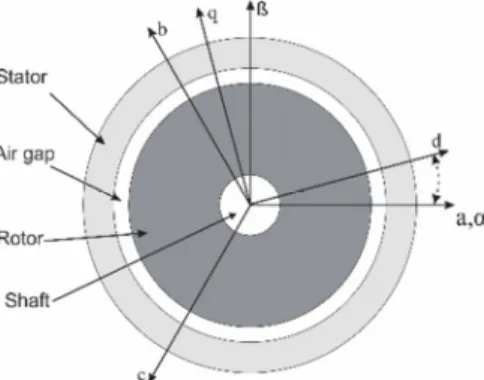
system, where the axes are perpendicular. Fig. 2 shows the scheme of the coordinate systems [14], [15].
Fig. 2. Cross section of induction motor with different coordinate systems
This operation is a multiplication of the three-phase voltage or current with the C transformation matrixes, where
{ = rs ss
t1 −. −. 0 √ −√
. . .
uv vv w
. (41)
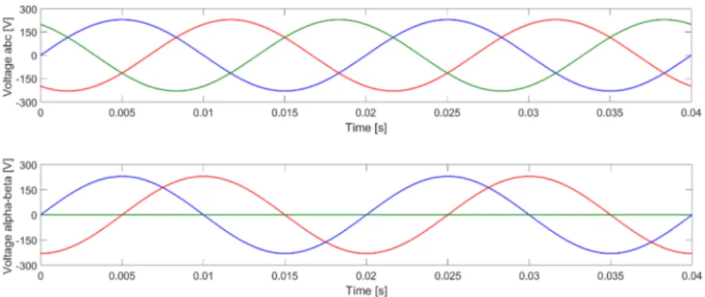
MATLAB simulations have been performed at the frequency of 50 Hz with a peak voltage amplitude of 230 V. The upper diagram in Fig. 3 shows the three-phase result, while the bottom one is the Clark transformed result in ? − } coordinate system. As it can be seen in the bottom diagram, the third signal is constant 0 V, and the phase difference between the sinusoidal voltages is 90 degrees.
Obtaining d-q signals, which is a tensor that rotates the reference frame, Park transformation must be performed on the Clark transformation result [15], [16]. The P transformation matrix is
~ = •cos € sin € 0
−sin € cos € 0
0 0 1ƒ, (42)
where € is the angle of the rotor relative to the stator.
In Fig. 4 the same three-phase voltage can be seen as in Fig. 3 and the Clark-Park transformation result in d-q coordinate system. The result shows the advantage of this transformation, where the resulted signals are going to be constant values.
Fig. 3. Three-phase sinusoidal voltage in ABC and ?-β coordinate system
Fig. 4. Three-phase sinusoidal voltage in abc and d-q coordinate system
It is important to note that no data loss occurs; the three-phase signal can be restored from the resulted signals in alpha-beta or d-q coordinate system with the appropriate inverse transformations.
Even if these transformations are already available in the model library in Simulink, it is considerable to implement the above mentioned transformations in complex models where fixed-step solver type has been chosen.
6. Results
For this work (35)-(38) has been implemented and simulations are performed in MATLAB & Simulink [17]. The same excitation has been used as in Section 5. The equations are in stator fix coordinate system, so the results of the Park transformations
are going to be sinusoidal current and voltage. The chosen motor parameters are summarized in Table I.
Table I
Lenze MCA10I40 induction machine parameters
Parameter Value
p 2
Lm 0.169 mH
Ls 0.1788 mH
Lr 0.179 mH
Rs 4.7 Ω
Rr 5.2 Ω
J 2.4 kg·cm2
D 0.0011 Nm·s/rad
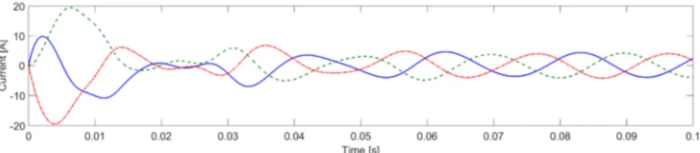
The stator current after the inverse Park and Clarke transformations can be seen in Fig. 5.
Fig. 5. Three-phase stator currents after inverse Park and Clarke transformation
To be able to see the change of the torque or rotating speed during operation, 1 Nm load torque has been used after 1 second. Fig. 6 shows the torque in the function of time.
As it can be seen after the transient phenomena are negligible, the torque is constant 0.172 Nm what is needed to overcome the resistant. The peak torque is 8.65 Nm, which is acceptable if the maximum torque Mn=10 Nm is given in the datasheet. After the load is taken into account it changes to 1.172 Nm.
Fig. 6. Torque produced by machine as a function of time
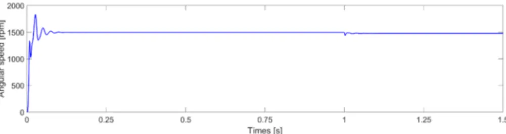
Fig. 7. shows the angular speed of the rotor.
Fig. 7. Angular speed of the shaft as a function of time
The nominal rotating speed is 3950 rpm at frequency of 140 Hz according to the datasheet. During the simulations, the frequency of the excitation signal was 50 Hz. The simulation result is 1497 rpm before the load torque has been applied because the mechanical model includes UQG'D in (38), so the slip is also included into the model.
After the transient phenomena caused by the load torque has ceased, the angular speed takes a value of 1479 rpm.
7. Conclusion
The objective of this work is to introduce the basic knowledge of state space modeling of induction machines. The necessary equations also included to can obtain the final form of the model.
Using rotating reference frame has been also introduced for future purposes, but these results has been performed by using stator fixed coordinate system. Because of that the Clarke and Park transformed three-phase sinusoidal voltage remains sinusoidal in d-q coordinate systems as well.
Finally, the simulation results have been compared with Krisztián Horváth’s results.
He used the same machine for measures and simulations as well and the results introduced here are correct.
These results and model provide a very good basis for the Linear Parameter Varying LPV/qLPV modeling, where the angular speed and the temperature are going to be the parameters.
Open Access statement
This is an open-access article distributed under the terms of the Creative Commons Attribution 4.0 International License (https://creativecommons.org/licenses/by/4.0/), which permits unrestricted use, distribution, and reproduction in any medium, provided the original author and source are credited, a link to the CC License is provided, and changes - if any - are indicated. (SID_1)
References
[1] Tabatabeeipour S. M., Stoustrup J., Bak T. Fault-tolerant control of descrete-time LPV systems using virtual actuators and sensors, Internation Journal of Robust and Nonlinear Control, Vol. 25, No. 5, 2015, pp. 707‒734.
[2] Khamari D., Makouf A., Drid S. Control of induction motor using polytopic LPV models, 2011 International Conference on Communications, Computer and Control Applications, Hammamet, Tunisia, 3-5 March 2011, pages 1‒5.
[3] Khamari D., Makouf A., Drid S., Chrifi-Alaoui L. High performance of self-scheduled linear parameter varying control with flux observer of induction motor, Journal of Electrical Engineering and Technology, Vol. 8, No. 5, 2013, pp. 1202‒1211.
[4] Kaiyu W., Chiasson J., Bodson M., Tolbert L. M. An online rotor time constant estimator for the induction machine, IEEE Transactions on Control Systems Technology, Vol. 15, No. 2, 2007, pp. 339‒348.
[5] Drid S., Benoudjit D., Csrifi-Alaoui L., Khamari D. A comparative study of rotor flux estimation in induction motor with linear parameter varying observer and Kalman filter, 15th International Conference on Science and Techniques of Automatic Control &
Computer Engineering, Hammamet, Tunisia, 21-23 December 2014, pp. 668‒672.
[6] Pan J., Westwick D., Nowicki E. Flux estimation of induction machines with linear parameter-varying system identification method, Canadian Conference on Electrical and Computer Engineering, Ontario, Canada, 2-5 May 2004, Vol. 4, pp. 2213‒2216.
[7] Bendtsen J. D., Trangbaek K., Descrete-time LPV current control of an induction motor, 42nd IEEE International Conference on Decision and Control, Maui, Hawaii, USA, December 9-12, 2003, pp. 5903‒5908.
[8] Prempain E., Postlethwaite I., Benchaib A. A linear parameter variant H-infinity control design for an induction motor, Control Engineering Practice, Vol. 10, No. 6, 2002, pp. 633‒644.
[9] Leonhard W. Control of electrical drives, Springer-Verlag, 1990.
[10] Marcsa D., Kuczmann M. Motion finite element simulation of a single-phase induction motor, Pollack Periodica, Vol. 4, No. 2, 2009, pp. 57‒66.
[11] Tranbaek K. Linear parameter varying control of induction motors, PhD Thesis, Aalborg University, Denmark, 2001.
[12] Rasmussen H. Self-tuning torque control of Induction motors for high performance application, PhD Thesis, Aalborg University, Denmark, 1995.
[13] Horváth K., Kuslits M. Dynamic performance of estimator-based speed sensorless control of induction machines using extended and unscented Kalman filters, Power Electronics and Drives, Vol. 3, No. 1, 2018, pp. 129‒144.
[14] Duesterhoeft W. C., Schulz M. W., Clarke E. Determination of instantaneous current and voltage by means of alpha, beta, and zero components, Transaction of the American Institute of Electrical Engineers, Vol. 70, No. 2, 1951, pp. 1248‒1255.
[15] Park R. H. Two-reaction theory of synchronous machines generalized method of analysis, Part I, Transactions of the American Institute of Electrical Engineers, Vol. 48, No. 3, 1929, pp. 716‒727.
[16] Kuslits M. Model-based control development of permanent magnet synchronous machines (in Hungarian), Publio Kiadó, Győr, 2016.
[17] Kovács G., Kuczmann M. Comparison of the different design software tools for the brushless DC motor designing, Pollack Periodica, Vol. 8, No. 1, 2013, pp. 179‒188.