Demonstration of Multimode Optical Fiber Communication System using 1300 nm Directly Modulated VCSEL for Gigabit Ethernet
INFOCOMMUNICATIONS JOURNAL
Demonstration of Multimode Optical Fiber Communication System using 1300 nm Directly Modulated VCSEL for Gigabit
Ethernet
1Tomáš Huszaník, 2Ján Turán, and 3Ľuboš Ovseník
> REPLACE THIS LINE WITH YOUR PAPER IDENTIFICATION NUMBER (DOUBLE-CLICK HERE TO EDIT) < 1
Abstract— In the recent years, the optical networks have grown to unexpected dimensions. The growth of active users and growing demand for data services set high requirements to network providers. Driving forces of this growth are multimedia, cloud computing and web services which set high bandwidth demand.
The majority of currently deployed optical networks utilize passive or active network structure using dominantly singlemode optical fiber (SMF). SMF is believed to be the better choice over multimode optical fiber (MMF) for high speed optical fiber communication systems. And in some applications it definitely is.
MMF has found use especially for short distance communication as it easily supports distances required for interconnecting buildings, data centres or campuses. Considering MMFs lower cost over SMF it became an interesting alternative for Ethernet connection in buildings or campuses. In this paper we present a simulation model of 1000BASE-LX Ethernet with MMF using different optical modulation techniques. The aim of this article is to demonstrate possibilities of MMF based 1000BASE-LX Ethernet with directly modulated vertical-cavity surface-emitting laser (VCSEL).
Keywords—Bit error rate, Ethernet, multimode optical fiber, optical modulation, singlemode optical fiber, VCSEL
I. INTRODUCTION
The first generation of optical networking started in the late 1970s. The first generation lightwave operated systems used GaAs semiconductor lasers and operated at 0.8 µm wavelength.
The first optical fiber systems used multimode fibers with core diameters of about 50 to 85 µm. A bit rate was not exceptionally high to these days - 45 Mbps and maximum distance was up to 10 km. The second generation came on scene in the early 1980s.
The bit rate of these early systems was limited to 100 Mbps mainly because of fiber dispersion in multimode fibers (MMF).
This limitation was quickly overcome by the use of singlemode optical fibers (SMF). Fiber dispersion is a very important design issue of optical fiber communication systems. Fiber dispersion leads to broadening of individual light pulses with propagation which cause inter-symbol interference (ISI). With
Affiliation: Department of Electronics and Multimedia Telecommunications, Technical University of Košice, Faculty of Electrical Engineering and Informatics, Košice, Slovakia. (corresponding author, e-mail:
tomas.huszanik@tuke.sk)
the interfered signal, it becomes impossible to recover signal accurately [1][2]. This problem is more obvious in the case of MMF, since different fiber modes spread different ways and different speeds. For this reason, majority of currently deployed optical systems use SMF. Despite historical development, the use of MMF over SMF can be still beneficial, especially for short distance transmissions. The most promising application of MMF is high-speed ethernet network, local and storage area networks [3]. As we prove in our experimental setup, MMF based Ethernet reaches today’s requirements for BER and OSNR (optical signal-to-noise ratio) and in some cases, goes even further [4][5][6]. The conclusions discussed in this work are based on the facts published in the following publications [7][8][9].
The section 2 provides a closer look at differences between MMF and SMF, detailed look at MMFs limitation factors and applications. In this article, we also present the practical application of MMF for the Ethernet connection. To show the performance of MMF based 1000BASE-LX Ethernet, we designed a simulation model using OptSim software. OptSim software is a professional program suite for advanced simulation of optical fiber systems. Thanks to the extension ModeSYS, we are able to fully evaluate multimode optical communication systems.
II. DESCRIPTION OF MULTIMODE OPTICAL FIBER COMMUNICATION
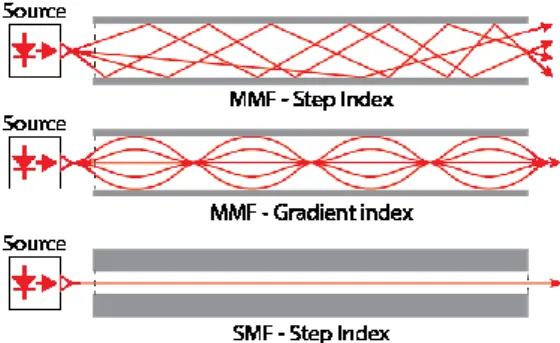
There are three basic types of optical fibers as shown in Fig.1: multimode fiber with step index, multimode fiber with graded index and singlemode fiber with step index.
Singlemode optical fiber allows only single light wave, also called lowest-order mode to propagate. The core diameter of singlemode optical fiber is 5-10 µm, the typical diameter of cladding is 125 µm. SMF is required for high data rate applications with low signal loss. The major advantage of SMF over MMF is that it does not suffer from modal dispersion that is the main limitation factor of MMF. However, there is still chromatic dispersion that limits the performance of SMF [6].
Demonstration of Multimode Optical Fiber Communication System using 1300 nm Directly Modulated VCSEL for Gigabit
Ethernet
1Tomáš Huszaník, 2Ján Turán, and 3Ľuboš Ovseník
> REPLACE THIS LINE WITH YOUR PAPER IDENTIFICATION NUMBER (DOUBLE-CLICK HERE TO EDIT) < 1
Abstract— In the recent years, the optical networks have grown to unexpected dimensions. The growth of active users and growing demand for data services set high requirements to network providers. Driving forces of this growth are multimedia, cloud computing and web services which set high bandwidth demand.
The majority of currently deployed optical networks utilize passive or active network structure using dominantly singlemode optical fiber (SMF). SMF is believed to be the better choice over multimode optical fiber (MMF) for high speed optical fiber communication systems. And in some applications it definitely is.
MMF has found use especially for short distance communication as it easily supports distances required for interconnecting buildings, data centres or campuses. Considering MMFs lower cost over SMF it became an interesting alternative for Ethernet connection in buildings or campuses. In this paper we present a simulation model of 1000BASE-LX Ethernet with MMF using different optical modulation techniques. The aim of this article is to demonstrate possibilities of MMF based 1000BASE-LX Ethernet with directly modulated vertical-cavity surface-emitting laser (VCSEL).
Keywords—Bit error rate, Ethernet, multimode optical fiber, optical modulation, singlemode optical fiber, VCSEL
I. INTRODUCTION
The first generation of optical networking started in the late 1970s. The first generation lightwave operated systems used GaAs semiconductor lasers and operated at 0.8 µm wavelength.
The first optical fiber systems used multimode fibers with core diameters of about 50 to 85 µm. A bit rate was not exceptionally high to these days - 45 Mbps and maximum distance was up to 10 km. The second generation came on scene in the early 1980s.
The bit rate of these early systems was limited to 100 Mbps mainly because of fiber dispersion in multimode fibers (MMF).
This limitation was quickly overcome by the use of singlemode optical fibers (SMF). Fiber dispersion is a very important design issue of optical fiber communication systems. Fiber dispersion leads to broadening of individual light pulses with propagation which cause inter-symbol interference (ISI). With
Affiliation: Department of Electronics and Multimedia Telecommunications, Technical University of Košice, Faculty of Electrical Engineering and Informatics, Košice, Slovakia. (corresponding author, e-mail:
tomas.huszanik@tuke.sk)
the interfered signal, it becomes impossible to recover signal accurately [1][2]. This problem is more obvious in the case of MMF, since different fiber modes spread different ways and different speeds. For this reason, majority of currently deployed optical systems use SMF. Despite historical development, the use of MMF over SMF can be still beneficial, especially for short distance transmissions. The most promising application of MMF is high-speed ethernet network, local and storage area networks [3]. As we prove in our experimental setup, MMF based Ethernet reaches today’s requirements for BER and OSNR (optical signal-to-noise ratio) and in some cases, goes even further [4][5][6]. The conclusions discussed in this work are based on the facts published in the following publications [7][8][9].
The section 2 provides a closer look at differences between MMF and SMF, detailed look at MMFs limitation factors and applications. In this article, we also present the practical application of MMF for the Ethernet connection. To show the performance of MMF based 1000BASE-LX Ethernet, we designed a simulation model using OptSim software. OptSim software is a professional program suite for advanced simulation of optical fiber systems. Thanks to the extension ModeSYS, we are able to fully evaluate multimode optical communication systems.
II. DESCRIPTION OF MULTIMODE OPTICAL FIBER COMMUNICATION
There are three basic types of optical fibers as shown in Fig.1: multimode fiber with step index, multimode fiber with graded index and singlemode fiber with step index.
Singlemode optical fiber allows only single light wave, also called lowest-order mode to propagate. The core diameter of singlemode optical fiber is 5-10 µm, the typical diameter of cladding is 125 µm. SMF is required for high data rate applications with low signal loss. The major advantage of SMF over MMF is that it does not suffer from modal dispersion that is the main limitation factor of MMF. However, there is still chromatic dispersion that limits the performance of SMF [6].
Demonstration of Multimode Optical Fiber Communication System using 1300 nm Directly Modulated VCSEL for Gigabit
Ethernet
1Tomáš Huszaník, 2Ján Turán, and 3Ľuboš Ovseník
> REPLACE THIS LINE WITH YOUR PAPER IDENTIFICATION NUMBER (DOUBLE-CLICK HERE TO EDIT) < 2 The term multimode refers to the multiple modes or paths
that are possible to transmit through the fiber. The typical core diameter of a multimode fiber used for telecommunication purposes is 50/62.5/125 µm. There are two principle types of multimode fiber – step index and graded index [6].
Fig. 1 Three types of optical fiber
The index of refraction profile of step index multimode fiber steps from low to high to low (from cladding to core to cladding). This type of fiber has large core diameter and numerical aperture. Step index multimode fiber is used for high bandwidth applications (over 1 GHz) supporting maximum 3 km transmission distance [10][11]. The number of modes propagating in a multimode step index fiber can be expressed as:
𝑀𝑀𝑛𝑛= 𝑉𝑉2⁄2 (1)
In this equation, V represents normalized frequency and it strongly relates to the size of fiber, refractive index and wavelength. Normalized frequency can be expressed in two ways:
𝑉𝑉 = [2𝜋𝜋𝜋𝜋 𝜆𝜆⁄ ] × 𝑁𝑁𝑁𝑁, (2) 𝑉𝑉 = [2𝜋𝜋𝜋𝜋 𝜆𝜆⁄ ] × 𝑛𝑛1× (2Δ)1⁄2, (3) where a is the fiber core radius, λ is operating wavelength, NA is numerical aperture, n1 is the refractive index of a core and finally, Δ is the relative refractive index difference between the core and cladding of an optical fiber [2][6][10]. The relationship between the angle of incoming light wave θi and the refracted wave θr inside step index MMF is:
𝑛𝑛0𝑠𝑠𝑠𝑠𝑛𝑛𝜃𝜃𝑖𝑖= 𝑛𝑛1𝜃𝜃𝑟𝑟 (4) Refraction is possible only for an angle ϕ meeting the following condition:
𝑠𝑠𝑠𝑠𝑛𝑛𝑠𝑠 < 𝑛𝑛2⁄𝑛𝑛1, (5) where n2 is the refractive index of cladding and n1 is the refractive index of core. Then the propagation of light wave inside the step index MMF is in Fig. 2 [10].
Fig. 2 Propagation of a light wave in step index MMF
Refractive index of the core of the graded index MMF decreases gradually from its maximum n1 value at the core to its minimum value n2 at the fibers cladding. This results into following light propagation – light wave travels faster at the edge of the core and slower in the center of the core. Individual modes travel in sinusoidal paths with equal travel time [6][9]. In comparison to step index MMF, the already mentioned travel pattern of light modes in graded index MMF significantly reduces modal dispersion. The light wave propagation in graded indexed MMF is illustrated in Fig. 3 [2][12].
Fig. 3 Propagation of a light wave in graded index MMF
The major limitation in multimode fiber optic communication system is intersysmbol interference (ISI) due to modal dispersion. This phenomenon is reduced in graded index MMFs, but it is still present. Modal dispersion can be eliminated using light sources that excite only the desired light modes which can be achieved by using spatial light modulators [12]. There are two main approaches when avoiding the signal degradation caused by modal dispersion. The first one is a mode filtering method. This method reduces higher order mode in the receiver. The second approach is a center-launching method which launches light directly into the center of the core of MMF which prevents the higher order mode occurrence.
Because of dispersion limitation, multimode fibers could be used especially for short links, for example in Ethernet networks. Later in this paper we present a simulation model of such a network. 1000BASE-LX is a fiber optic Gigabit Ethernet standard specified in IEEE 802.3 Clause 38. It has been developed for implementing Gigabit ethernet networks. Specification of optical interface for 1000BASE-LX is shown in Table 1 [13].
III. EXPERIMENTAL MODEL OF 1000BASE-LXETHERNET For the purpose of evaluating performance of 1000BASE- LX Ethernet with MMF we used OptSim software and extention module ModeSYS. When building this model, we respected IEEE 802.3 Clause 38 which specifies 1000BASE-
> REPLACE THIS LINE WITH YOUR PAPER IDENTIFICATION NUMBER (DOUBLE-CLICK HERE TO EDIT) < 1
Abstract— In the recent years, the optical networks have grown to unexpected dimensions. The growth of active users and growing demand for data services set high requirements to network providers. Driving forces of this growth are multimedia, cloud computing and web services which set high bandwidth demand.
The majority of currently deployed optical networks utilize passive or active network structure using dominantly singlemode optical fiber (SMF). SMF is believed to be the better choice over multimode optical fiber (MMF) for high speed optical fiber communication systems. And in some applications it definitely is.
MMF has found use especially for short distance communication as it easily supports distances required for interconnecting buildings, data centres or campuses. Considering MMFs lower cost over SMF it became an interesting alternative for Ethernet connection in buildings or campuses. In this paper we present a simulation model of 1000BASE-LX Ethernet with MMF using different optical modulation techniques. The aim of this article is to demonstrate possibilities of MMF based 1000BASE-LX Ethernet with directly modulated vertical-cavity surface-emitting laser (VCSEL).
Keywords—Bit error rate, Ethernet, multimode optical fiber, optical modulation, singlemode optical fiber, VCSEL
I. INTRODUCTION
The first generation of optical networking started in the late 1970s. The first generation lightwave operated systems used GaAs semiconductor lasers and operated at 0.8 µm wavelength.
The first optical fiber systems used multimode fibers with core diameters of about 50 to 85 µm. A bit rate was not exceptionally high to these days - 45 Mbps and maximum distance was up to 10 km. The second generation came on scene in the early 1980s.
The bit rate of these early systems was limited to 100 Mbps mainly because of fiber dispersion in multimode fibers (MMF).
This limitation was quickly overcome by the use of singlemode optical fibers (SMF). Fiber dispersion is a very important design issue of optical fiber communication systems. Fiber dispersion leads to broadening of individual light pulses with propagation which cause inter-symbol interference (ISI). With
Affiliation: Department of Electronics and Multimedia Telecommunications, Technical University of Košice, Faculty of Electrical Engineering and Informatics, Košice, Slovakia. (corresponding author, e-mail:
tomas.huszanik@tuke.sk)
the interfered signal, it becomes impossible to recover signal accurately [1][2]. This problem is more obvious in the case of MMF, since different fiber modes spread different ways and different speeds. For this reason, majority of currently deployed optical systems use SMF. Despite historical development, the use of MMF over SMF can be still beneficial, especially for short distance transmissions. The most promising application of MMF is high-speed ethernet network, local and storage area networks [3]. As we prove in our experimental setup, MMF based Ethernet reaches today’s requirements for BER and OSNR (optical signal-to-noise ratio) and in some cases, goes even further [4][5][6]. The conclusions discussed in this work are based on the facts published in the following publications [7][8][9].
The section 2 provides a closer look at differences between MMF and SMF, detailed look at MMFs limitation factors and applications. In this article, we also present the practical application of MMF for the Ethernet connection. To show the performance of MMF based 1000BASE-LX Ethernet, we designed a simulation model using OptSim software. OptSim software is a professional program suite for advanced simulation of optical fiber systems. Thanks to the extension ModeSYS, we are able to fully evaluate multimode optical communication systems.
II. DESCRIPTION OF MULTIMODE OPTICAL FIBER COMMUNICATION
There are three basic types of optical fibers as shown in Fig.1: multimode fiber with step index, multimode fiber with graded index and singlemode fiber with step index.
Singlemode optical fiber allows only single light wave, also called lowest-order mode to propagate. The core diameter of singlemode optical fiber is 5-10 µm, the typical diameter of cladding is 125 µm. SMF is required for high data rate applications with low signal loss. The major advantage of SMF over MMF is that it does not suffer from modal dispersion that is the main limitation factor of MMF. However, there is still chromatic dispersion that limits the performance of SMF [6].
Demonstration of Multimode Optical Fiber Communication System using 1300 nm Directly Modulated VCSEL for Gigabit
Ethernet
1Tomáš Huszaník, 2Ján Turán, and 3Ľuboš Ovseník
> REPLACE THIS LINE WITH YOUR PAPER IDENTIFICATION NUMBER (DOUBLE-CLICK HERE TO EDIT) < 1
Abstract— In the recent years, the optical networks have grown to unexpected dimensions. The growth of active users and growing demand for data services set high requirements to network providers. Driving forces of this growth are multimedia, cloud computing and web services which set high bandwidth demand.
The majority of currently deployed optical networks utilize passive or active network structure using dominantly singlemode optical fiber (SMF). SMF is believed to be the better choice over multimode optical fiber (MMF) for high speed optical fiber communication systems. And in some applications it definitely is.
MMF has found use especially for short distance communication as it easily supports distances required for interconnecting buildings, data centres or campuses. Considering MMFs lower cost over SMF it became an interesting alternative for Ethernet connection in buildings or campuses. In this paper we present a simulation model of 1000BASE-LX Ethernet with MMF using different optical modulation techniques. The aim of this article is to demonstrate possibilities of MMF based 1000BASE-LX Ethernet with directly modulated vertical-cavity surface-emitting laser (VCSEL).
Keywords—Bit error rate, Ethernet, multimode optical fiber, optical modulation, singlemode optical fiber, VCSEL
I. INTRODUCTION
The first generation of optical networking started in the late 1970s. The first generation lightwave operated systems used GaAs semiconductor lasers and operated at 0.8 µm wavelength.
The first optical fiber systems used multimode fibers with core diameters of about 50 to 85 µm. A bit rate was not exceptionally high to these days - 45 Mbps and maximum distance was up to 10 km. The second generation came on scene in the early 1980s.
The bit rate of these early systems was limited to 100 Mbps mainly because of fiber dispersion in multimode fibers (MMF).
This limitation was quickly overcome by the use of singlemode optical fibers (SMF). Fiber dispersion is a very important design issue of optical fiber communication systems. Fiber dispersion leads to broadening of individual light pulses with propagation which cause inter-symbol interference (ISI). With
Affiliation: Department of Electronics and Multimedia Telecommunications, Technical University of Košice, Faculty of Electrical Engineering and Informatics, Košice, Slovakia. (corresponding author, e-mail:
tomas.huszanik@tuke.sk)
the interfered signal, it becomes impossible to recover signal accurately [1][2]. This problem is more obvious in the case of MMF, since different fiber modes spread different ways and different speeds. For this reason, majority of currently deployed optical systems use SMF. Despite historical development, the use of MMF over SMF can be still beneficial, especially for short distance transmissions. The most promising application of MMF is high-speed ethernet network, local and storage area networks [3]. As we prove in our experimental setup, MMF based Ethernet reaches today’s requirements for BER and OSNR (optical signal-to-noise ratio) and in some cases, goes even further [4][5][6]. The conclusions discussed in this work are based on the facts published in the following publications [7][8][9].
The section 2 provides a closer look at differences between MMF and SMF, detailed look at MMFs limitation factors and applications. In this article, we also present the practical application of MMF for the Ethernet connection. To show the performance of MMF based 1000BASE-LX Ethernet, we designed a simulation model using OptSim software. OptSim software is a professional program suite for advanced simulation of optical fiber systems. Thanks to the extension ModeSYS, we are able to fully evaluate multimode optical communication systems.
II. DESCRIPTION OF MULTIMODE OPTICAL FIBER COMMUNICATION
There are three basic types of optical fibers as shown in Fig.1: multimode fiber with step index, multimode fiber with graded index and singlemode fiber with step index.
Singlemode optical fiber allows only single light wave, also called lowest-order mode to propagate. The core diameter of singlemode optical fiber is 5-10 µm, the typical diameter of cladding is 125 µm. SMF is required for high data rate applications with low signal loss. The major advantage of SMF over MMF is that it does not suffer from modal dispersion that is the main limitation factor of MMF. However, there is still chromatic dispersion that limits the performance of SMF [6].
Demonstration of Multimode Optical Fiber Communication System using 1300 nm Directly Modulated VCSEL for Gigabit
Ethernet
1Tomáš Huszaník, 2Ján Turán, and 3Ľuboš Ovseník
using 1300 nm Directly Modulated VCSEL for Gigabit Ethernet
> REPLACE THIS LINE WITH YOUR PAPER IDENTIFICATION NUMBER (DOUBLE-CLICK HERE TO EDIT) < 1
Abstract— In the recent years, the optical networks have grown to unexpected dimensions. The growth of active users and growing demand for data services set high requirements to network providers. Driving forces of this growth are multimedia, cloud computing and web services which set high bandwidth demand.
The majority of currently deployed optical networks utilize passive or active network structure using dominantly singlemode optical fiber (SMF). SMF is believed to be the better choice over multimode optical fiber (MMF) for high speed optical fiber communication systems. And in some applications it definitely is.
MMF has found use especially for short distance communication as it easily supports distances required for interconnecting buildings, data centres or campuses. Considering MMFs lower cost over SMF it became an interesting alternative for Ethernet connection in buildings or campuses. In this paper we present a simulation model of 1000BASE-LX Ethernet with MMF using different optical modulation techniques. The aim of this article is to demonstrate possibilities of MMF based 1000BASE-LX Ethernet with directly modulated vertical-cavity surface-emitting laser (VCSEL).
Keywords—Bit error rate, Ethernet, multimode optical fiber, optical modulation, singlemode optical fiber, VCSEL
I. INTRODUCTION
The first generation of optical networking started in the late 1970s. The first generation lightwave operated systems used GaAs semiconductor lasers and operated at 0.8 µm wavelength.
The first optical fiber systems used multimode fibers with core diameters of about 50 to 85 µm. A bit rate was not exceptionally high to these days - 45 Mbps and maximum distance was up to 10 km. The second generation came on scene in the early 1980s.
The bit rate of these early systems was limited to 100 Mbps mainly because of fiber dispersion in multimode fibers (MMF).
This limitation was quickly overcome by the use of singlemode optical fibers (SMF). Fiber dispersion is a very important design issue of optical fiber communication systems. Fiber dispersion leads to broadening of individual light pulses with propagation which cause inter-symbol interference (ISI). With
Affiliation: Department of Electronics and Multimedia Telecommunications, Technical University of Košice, Faculty of Electrical Engineering and Informatics, Košice, Slovakia. (corresponding author, e-mail:
tomas.huszanik@tuke.sk)
the interfered signal, it becomes impossible to recover signal accurately [1][2]. This problem is more obvious in the case of MMF, since different fiber modes spread different ways and different speeds. For this reason, majority of currently deployed optical systems use SMF. Despite historical development, the use of MMF over SMF can be still beneficial, especially for short distance transmissions. The most promising application of MMF is high-speed ethernet network, local and storage area networks [3]. As we prove in our experimental setup, MMF based Ethernet reaches today’s requirements for BER and OSNR (optical signal-to-noise ratio) and in some cases, goes even further [4][5][6]. The conclusions discussed in this work are based on the facts published in the following publications [7][8][9].
The section 2 provides a closer look at differences between MMF and SMF, detailed look at MMFs limitation factors and applications. In this article, we also present the practical application of MMF for the Ethernet connection. To show the performance of MMF based 1000BASE-LX Ethernet, we designed a simulation model using OptSim software. OptSim software is a professional program suite for advanced simulation of optical fiber systems. Thanks to the extension ModeSYS, we are able to fully evaluate multimode optical communication systems.
II. DESCRIPTION OF MULTIMODE OPTICAL FIBER COMMUNICATION
There are three basic types of optical fibers as shown in Fig.1: multimode fiber with step index, multimode fiber with graded index and singlemode fiber with step index.
Singlemode optical fiber allows only single light wave, also called lowest-order mode to propagate. The core diameter of singlemode optical fiber is 5-10 µm, the typical diameter of cladding is 125 µm. SMF is required for high data rate applications with low signal loss. The major advantage of SMF over MMF is that it does not suffer from modal dispersion that is the main limitation factor of MMF. However, there is still chromatic dispersion that limits the performance of SMF [6].
Demonstration of Multimode Optical Fiber Communication System using 1300 nm Directly Modulated VCSEL for Gigabit
Ethernet
1Tomáš Huszaník, 2Ján Turán, and 3Ľuboš Ovseník
> REPLACE THIS LINE WITH YOUR PAPER IDENTIFICATION NUMBER (DOUBLE-CLICK HERE TO EDIT) < 2 The term multimode refers to the multiple modes or paths
that are possible to transmit through the fiber. The typical core diameter of a multimode fiber used for telecommunication purposes is 50/62.5/125 µm. There are two principle types of multimode fiber – step index and graded index [6].
Fig. 1 Three types of optical fiber
The index of refraction profile of step index multimode fiber steps from low to high to low (from cladding to core to cladding). This type of fiber has large core diameter and numerical aperture. Step index multimode fiber is used for high bandwidth applications (over 1 GHz) supporting maximum 3 km transmission distance [10][11]. The number of modes propagating in a multimode step index fiber can be expressed as:
𝑀𝑀𝑛𝑛= 𝑉𝑉2⁄2 (1)
In this equation, V represents normalized frequency and it strongly relates to the size of fiber, refractive index and wavelength. Normalized frequency can be expressed in two ways:
𝑉𝑉 = [2𝜋𝜋𝜋𝜋 𝜆𝜆⁄ ] × 𝑁𝑁𝑁𝑁, (2) 𝑉𝑉 = [2𝜋𝜋𝜋𝜋 𝜆𝜆⁄ ] × 𝑛𝑛1× (2Δ)1⁄2, (3) where a is the fiber core radius, λ is operating wavelength, NA is numerical aperture, n1 is the refractive index of a core and finally, Δ is the relative refractive index difference between the core and cladding of an optical fiber [2][6][10]. The relationship between the angle of incoming light wave θi and the refracted wave θr inside step index MMF is:
𝑛𝑛0𝑠𝑠𝑠𝑠𝑛𝑛𝜃𝜃𝑖𝑖= 𝑛𝑛1𝜃𝜃𝑟𝑟 (4) Refraction is possible only for an angle ϕ meeting the following condition:
𝑠𝑠𝑠𝑠𝑛𝑛𝑠𝑠 < 𝑛𝑛2⁄𝑛𝑛1, (5) where n2 is the refractive index of cladding and n1 is the refractive index of core. Then the propagation of light wave inside the step index MMF is in Fig. 2 [10].
Fig. 2 Propagation of a light wave in step index MMF
Refractive index of the core of the graded index MMF decreases gradually from its maximum n1 value at the core to its minimum value n2 at the fibers cladding. This results into following light propagation – light wave travels faster at the edge of the core and slower in the center of the core. Individual modes travel in sinusoidal paths with equal travel time [6][9]. In comparison to step index MMF, the already mentioned travel pattern of light modes in graded index MMF significantly reduces modal dispersion. The light wave propagation in graded indexed MMF is illustrated in Fig. 3 [2][12].
Fig. 3 Propagation of a light wave in graded index MMF The major limitation in multimode fiber optic communication system is intersysmbol interference (ISI) due to modal dispersion. This phenomenon is reduced in graded index MMFs, but it is still present. Modal dispersion can be eliminated using light sources that excite only the desired light modes which can be achieved by using spatial light modulators [12]. There are two main approaches when avoiding the signal degradation caused by modal dispersion. The first one is a mode filtering method. This method reduces higher order mode in the receiver. The second approach is a center-launching method which launches light directly into the center of the core of MMF which prevents the higher order mode occurrence.
Because of dispersion limitation, multimode fibers could be used especially for short links, for example in Ethernet networks. Later in this paper we present a simulation model of such a network. 1000BASE-LX is a fiber optic Gigabit Ethernet standard specified in IEEE 802.3 Clause 38. It has been developed for implementing Gigabit ethernet networks.
Specification of optical interface for 1000BASE-LX is shown in Table 1 [13].
III. EXPERIMENTAL MODEL OF 1000BASE-LXETHERNET For the purpose of evaluating performance of 1000BASE- LX Ethernet with MMF we used OptSim software and extention module ModeSYS. When building this model, we respected IEEE 802.3 Clause 38 which specifies 1000BASE-
Demonstration of Multimode Optical Fiber Communication System
using 1300 nm Directly Modulated VCSEL for Gigabit Ethernet > REPLACE THIS LINE WITH YOUR PAPER IDENTIFICATION NUMBER (DOUBLE-CLICK HERE TO EDIT) < 4
C. Receiver section
Receiver section is formed with optical low pass Bessel filter and APD (avalanche photodiode) detector with 0.8 quantum efficiency. This compound component also contains optical preamplifier and electrical Bessel filter. Receiver sensitivity is set to -19 dBm and electrical filter bandwidth is 1.5 GHz. Optical scopes are used to analyze optical spectrums.
Eye analyzer is used to observe eye diagram display. BER analyzer calculates BER and Q factor performance.
IV. RESULTS AND DISCUSSION
To evaluate performance of 1000BASE-LX Ethernet we established two experimental setups. First experimental setup uses NRZ encoding method and VCSEL optical direct modulation. NRZ encoding scheme is defined as follows – higher signal value is represented by logic 1 and the lower value is always logic 0 and the duration of the bit interval does not change. The change occurs by changing the value of the following information bit. The second experimental setup uses RZ encoding scheme with VCSEL optical direct modulation.
With RZ encoding scheme, duration of information bit is reduced to half. RZ encoding scheme requires double bandwidth compared to NRZ which is the reason why are RZ pulses are broadened more by fiber dispersion.
To fully evaluate system performance, we scanned various parameters of proposed simulation model that are key to the system performance. Input optical spectrums for NRZ and RZ encoding scheme are shown in Fig.7 and Fig. 8.
Performance of the system was evaluated using BER and Q factor measurement. These measurements were obtained by analyzing eye diagram display. Eye diagram is used to observe the quality of received signal in digital domain. We can extract a lot of parameters just by analyzing the display. The most obvious one is eye opening - the most open part means the best OSNR (optical signal-to-noise ratio). Q factor, function of OSNR, is another parameter that can be extracted. Q factor provides a qualitative description of receiver performance.
Fig. 7 Input optical spectrum for NRZ
Fig. 8 Input optical spectrum for RZ
Fig. 9 Eye diagram for NRZ and 550 m MMF
Fig. 10 Eye diagram for RZ and 550 m MMF
First experimental run was performed for 550 m MMF with 1.5 dB/km attenuation while launch power was -11.5 dB and operating wavelength 1300 nm. From the obtained eye diagrams shown in Fig. 9 and Fig. 10 one can say, that system performance in these conditions are exceptionally good. Values of BER and Q factor are provided in Table 2.
> REPLACE THIS LINE WITH YOUR PAPER IDENTIFICATION NUMBER (DOUBLE-CLICK HERE TO EDIT) < 3
Fig. 4 Block scheme of 1000BASE-LX Ethernet simulation model LX standard. Block scheme of designed 1000BASE-LX
Ethernet network with MMF and the vertical-cavity surface- emitting laser (VCSEL) is shown in Fig. 4. Detailed description of simulation scheme is in the following subsections.
TABLE I. SPECIFICATIONS OF 1000BASE-LXETHERNET
Parameter Value
Bitrate 1/1.25 Gbps
Optical interface MMF and SMF
Fiber diameter 50/62.5/125 µm (MMF), 9/10 µm (SMF)
Transmission distance 550 m for 62.5/125 and 50/125 for MMF cable
10 km for 9/125 SMF cable Operating wavelength 1270 – 1355 nm
Launch power -11.5 to -3 dBm
Receive power -19 to -3 dBm
Receiver saturation -3 dBm
Receiver sensitivity -19 dBm
A. Transmitter section
Transmitter of proposed multimode fiber based 1000BASE- LX Ethernet consists of pseudorandom binary sequence (PRBS) generator which is difficult to predict and exhibit statistical behaviour. Transmission rate is 1.25 Gbps. Data are then modulated using electrical modulator driver – NRZ or RZ, depending on simulation setup. NRZ/RZ signal is then modulated to an optical carrier using VCSEL. A vertical-cavity surface-emitting laser (VCSEL) is a high efficiency semiconductor- based laser optimized for use with multimode fibers. VCSEL emits beam verticaly from its top surface. High speed fiber links based on multimode fiber use VCSELs and GaAs photodetectors. Development of these components is extremely important for future multimode fiber systems development [8]. Central wavelength of VCSEL in our scheme is 1300 nm. Excitation ratio is 9 dB, linewidth is 4nm and launch power is -11.5 dB. Transverse mode of VCSEL used in our simulation model is shown in Fig. 5.
Next in the chain is optical linewidth adder and optical power normalizer. To simulate insertion loss between optical transmitter and optical fiber we used connector components with insertion loss 0.75 dB.
B. Transmission section
To eliminate modal dispersion, we opted for gradient index multimode fiber. Multimode fiber used in our simulation is 550 m long, which is the maximum excepted length, with diameter of 50 µm and attenuation of 1.5 dB/km. Fiber bandwidth is 500 MHz. Peak refractive index is 1.475 and index step is 1%.
Dispersion slope is 0.11 ps/km nm2. Plot of refractive index of MMF is illustrated on Fig. 6.
Fig. 5 Transverse mode of VCSEL
Fig. 6 Refractive index of MMF