A Review of Bilateral Teleoperation Algorithms
Riccardo Muradore and Paolo Fiorini
Riccardo Muradore and Paolo Fiorini are with the Department of Computer Science, University of Verona, Strada Le Grazie 15, 37134 Verona, Italy.
riccardo.muradore@univr.it, paolo.fiorini@univr.it
Abstract: Bilateral Teleoperation is a key technology to allow humans to interact with remote environments by providing the operator with haptic feedback. Haptic feedback from the one hand improves human perception and therefore the quality of the human-robot interaction, on the other hand it can tamper with the stability of the system when the communication between the master side (where the operator is) and the slave side (where the remote robot interacts with the environment) is not instantaneous but affected by delay and packet drops.
In the last 40 years many algorithms have been developed to guarantee the stability of haptic teleoperation in the presence of time delay, many of them based on passivity theory. In this paper we review and compare a few algorithms that are representative of the tools in the frequency or in the time domains that have been used to develop a safe and transparent physical human-robot interaction with unknown environments.
Keywords: Bilateral teleoperation, Passivity, Communication delay, Haptics, Force reflec- tion.
1 Introduction
Teleoperation ofmechanicalarms markedthe beginningof roboticsdevelopment andithasbeenanimportantcomponentofthisfieldevers ince.Teleoperationsys- temsallowhumanstointeractwithremoteenvironmentsbyprovidingtheoperator withsensoryfeedbacksimilartothats/hewouldexperienceasiftheywereatthe remotesite.Toachievefullsensoryfeedback,teleoperationsystemsshouldcommu- nicate also use contactforce/torqueinformation, fromtheslavetothemastersideto improve human perception and understanding, improve task performance and achievethe telepresence. The specific teleoperation configuration, in which, the kinesthetic coupling betweenoperator andenvironment is enhanced bydynamic coupling,isreferredtoasbilateralteleoperation,sinceitprovidesforcefeedback.
Thishasbeenoneof thefieldsp ioneeredb yA ntal( Tony)B ejczya ndt hisreview aimsatshowingthewidelegacyofhisinitialresearch.
Current examples of teleoperation span from space applications [1, 2] to rehabilita- tion, to surgery [3] and to Unmanned Air/Ground Vehicles (UAV, UGV).
A large number of papers have been written on the various aspects of teleoperation as shown in many survey papers [4, 5, 6], thus indicating a significant interest in the field; however these survey papers present mostly the analytical aspects of the reviewed algorithms without comparison and discussion of experimental results.
To fill this gap, we have added to our research in teleoperation, a series of experiments to analysein detail the most common teleoperation algorithms with the goal of developing a unified classification of the field and of formalising a curriculuminteleoperationstudies thatcould be of benefittothe wholerobotics community. Wefocus thisreviewonbilateral teleoperationsystems inwhichthe masterandtheslavedevicesareconnectedthrough a packet-basedcommunication channel which delivers the signals, such as commands from the masters and measurements from the slave. Although this architecture is not the most commonly used in real systems, becauseof the potentialinstability duetoforce feedbackinthepresenceofcommu-nicationtimedelay,itsurelymustbeanalyzed anddiscussedbecauseitprovidestheoperatorthefullperceptionoftheremoteside [7,8,9].
In this paper, we present the initial results of our classification and analysis of the hundredsof teleoperation algorithmsavailable inthe scientificliterature. We focus on algorithms that guarantee stability of the bilateral teleoperation system and we group them according the time delay present in the communication channel. Foreachalgorithmweshowitsblockdiagramanditsbasicequations.
In section2we discussonealgorithmfor thecommunicationwithouttimedelay.
In section3wepresenttwoalgorithmsthatcompensateanunknown butconstant communicationtimedelay. Finally,inSection4,wepresentthreealgorithmsthat supportforcefeedbackinthepresenceofvariablecommunicationtimedelayandof datapacketlosses. Section5describestheexperimentalset-uponwhichwecom- paretheperformanceofthevariousalgorithms,someofthe hardwarecalibration detailsandtheresultsofsomeexperiments. Itmustbenotedthattheexperimental data presented, were the resultsof the workof the students followingthe course inAdvanced Robotics offered at our University. Finally, Section 6 summarizes the paper and presents our plans to continue the analysis of teleoperation algorithms.
2 Bilateral teleoperation with no communication delay
Even ifmostteleoperationalgorithmsfacecommunicationdelays,therearemany important applications wheretheteleoperated systemusesdedicated communica- tionchannels (e.g. DaVincisurgicalrobot,ESAsystem), without any timedelay noticeablebytheuser.
2.1 Four channel teleoperation architecture
Among the many algorithms that consider the bilateral teleoperation without com- munication delay we analyse the one proposed by Lawrence in 1993, theFour chan- nel architecture[10].
The teleoperation system is completely transparent if the operator feels that s/he is directly interacting with the remote environment (equal forcesfm=fsand velocities vm=vs).TransparencyrequiresthatthetransmittedimpedanceZtisequaltothe environment impedanceZe=vfs
s. According to the block diagram in Figure 1 we have to design the blocksCs,Cm,C1, . . . .C4in such a way that the hybrid matrixH fm(s)
vm(s)
=
H11(s) H12(s) H21(s) H22(s)
vs(s) fs(s)
(1) is equal to the matrix
0 I
−I 0
. This implies Zt= fm
vm = (H11−H12Ze)(H21−H22Ze)−1=Ze. (2) Toachievethisgoalitisnecessarytohaveveryaccuratemodelsofthemasterand slaverobots, otherwisethetransparencyconditionwillnot besatisfied.Howeverit is worth highlighting, that good transparency is important mainly at low frequencies, i.e. where the operator is working and where, fortunately, the mathematicalmodelsaremoreaccurate.
Zh
Zm−1
Cm
C3
C1
C4
C2
Cs
Zs−1
Ze
− +
−− +
− fh⋆
fcm
vm +
− − fcs
vs
Master Communication Slave channel
fm
fe⋆
fs + +
Figure 1
Four channel force-velocity architecture. Legend: Zhoperator arm impedance,Zm−1master robot ad- mittance,Zeenvironment impedance,Zs−1slave robot admittance;Cmmaster local controller,Csslave local controller,C1, . . . ,C4communication link transfer functions; fh?operator intentional force,fm,vm
force and velocity at the master side,fs,vsforce and velocity at the slave side,fe?exogenous force at the remote site,fcm,fcsforce controls at the master and slave side, respectively.
2.1.1 Discussion
Themain tasks whenusingthisalgorithmare:
Analysetheimpactofthediscretisationontransparency
IdentifytherealvaluesoftheelementsinH byusingtimeseriesof velocities and forces, and compare them with the ideal values
Consider the effects of model uncertainty and static friction
3 Bilateral teleoperation with constant and unknown communication delay
In several teleoperation systems the communication delay cannot be neglected but it can be assumed constant but unknown. The following approaches exploit the con- stant delay hypothesis to design control architectures that guarantee the stability of the system independently of the delay and the interaction with passive environments.
3.1 Wave variables and Scattering transformation
The architecture proposed in [11] transmits wave variables{um,wm},{us,ws}in- stead of power variables{fm,vm},{fs,vs}to guarantee the passivity of the system.
The wave transformation relating wave and power variables is given by um= 1
√2b(fm+bvm), us= 1
√2b(fs−bvs), (3) wm= 1
√2b(fm−bvm), ws= 1
√2b(fs+bvs) (4) wherebis the characteristic impedance. The value ofbis a design parameter. Fig- ure 2 shows the architecture where we exploit the fact that the wave transformation is invertible and so the power variables can be retrieved from the wave variables
fm= rb
2(um+wm), fs= rb
2(us+ws), (5)
vm= 1
√2b(um−wm), vs=− 1
√2b(us−ws). (6) Due to the communication delayτ, we have
ws(t) = um(t−τ) (7)
wm(t) = us(t−τ). (8)
It is worth remarking that whenτ=0, transmitting wave variables is the same to transmit power variables.
The control architecture consists also of a velocity controller at the slave side whereas the force measured fsis sent to the haptic devices for force rendering.
The solution of the time delay problem proposed in this algorithm shows why time delay may generate energy (and so destabilise the system) and how the wave trans- formation solves this problem [11].
um
wm
ws
us
Communication channel
Master Slave
1 b
vs
fs +
+
−
− +
+
+ +
√1 2b
vm
fm
b √
2b
√1 2b
√2b
τ
τ
Figure 2
Wave variables. Legend:{um,wm},{us,ws}wave variables at master and slave side;{fm,vm},{fs,vs} power variables at master and slave side;τconstant communication delay;bcharacteristic impedance.
3.1.1 Discussion
The main aspects in the implementation of this algorithm are:
• The system at the master side behaves in a sluggish way also when the slave is in free motion. This behavior is function of the communication delayτe the value ofb.
• The parameterbshould be tuned according to the delayτ.
• The transparency of the scheme in Figure 2 should be compared to the one having termination elements to match the impedances, which also introduce scaling in force (master side) and velocity (slave side).
3.2 PD and passivity terms
The solution proposed by Lee and Spong guarantees the stability of a position- position bilateral teleoperation by adding a dissipative term to the PD controller at each side of the architecture [12].
As shown in Figure 3 the master and slave controllers are given by um(t) = −Kpx˜m(t)−Kvv˜m(t)
| {z }
fcm
−(Kdis+Pε)vm(t)
| {z }
fpm,dissipation
(9) us(t) = −Kpx˜s(t)−Kvv˜s(t)
| {z }
fcs
−(Kdis+Pε)vs(t)
| {z }
fps,dissipation
(10)
where ˜xm(t):=xs(t−τs2m)−xm(t),v˜m(t):=vs(t−τs2m)−vm(t)and ˜xs(t):=xm(t− τm2s)−xs(t),v˜s(t):=vm(t−τm2s)−vs(t)are the position/velocity tracking errors at the master and slave side, respectively. The gainKdisis needed to ensure passivity of the P-control action (Kdiss=τ¯RT T2 Kp, where ¯τRT T is an upper bound of the round trip time ¯τRT T ≥τRT T :=τm2s+τs2m) andPεadds additional damping to guarantee the master-slave position coordination.
3.2.1 Discussion
The main issues to be considered when using this algorithm are:
−
−
+ + + +
+
− +
fcs
+
fs
xsd
vsd
xs Zs−1 +
+ Kp
Kv
Kdis
Pε
fps
˜ vs
˜ xs
vs
fm
+ +
−
− vmd
xmd
˜ vm
˜ xm + +
+ + fpm
fcm + +
−
+ vm
xm
Pε
Kdis
Kv
Kp
Z−1m
Communication
channel Slave
Master
τm2s
τs2m
Figure 3
PD and passivity terms. Legend: Zm−1 master robot admittance,Zs−1 slave robot admittance;Kp,Kv position and velocity gains of the PD controller;Kdis,Pεdissipative terms;fm,xm,vmforce, position and velocity at the master side,fs,xs,vsforce, position and velocity at the slave side;fcm,fcsforce controls at the master and slave side,fpm,fpspassivity-related forces.
• The effect of the discretization and of the velocity estimation.
• The speed of the system response as a function ofKdis (and so of Kpand τRT T).
• The effect of the values ofKpandKvat the master and slave sides.
• The effect ofPεon the level of transparency.
• The on-line adaptation ofKdisaccording to the measured delay.
3.3 Adaptive algorithm
The algorithm presented in this section for the constant communication delay sce- nario makes use of adaptive control to guarantee the passivity of the system [13].
In this algorithm, the PD controllers of the previous approach are replaced by an equivalent proportional controller on the new variables:
rm(t) := vm(t) +λxm(t) (11)
rs(t) := vs(t) +λxs(t) (12)
whereλ >0 is a tuning parameter. The overall architecture is shown in Figure 4 where theAdaptive Estimationblocks estimate the inertia and damping parameters of the DC motor at the slave and master side using an adaptive algorithm.
"
J˙ˆm(t) B˙ˆm(t)
#
= ΓmYmT(xm(t),rm(t))rm(t) (13)
"
J˙ˆs(t) B˙ˆs(t)
#
= ΓsYsT(xs(t),rs(t))rs(t) (14)
whereΓm,Γs are constant positive definite matrices andYm,Ys are the regression matrices.
The overall master and slave controls are computed as:
um(t) = fmc(t)−Jˆm(t)λvm(t)−Bˆm(t)λxm(t) (15) us(t) = fsc(t)−Jˆs(t)λvs(t)−Bˆs(t)λxs(t) (16) where fmc(t)and fsc(t)are the coordinating torques
fmc(t) = K(rm(t)−rs(t−τs2m)) (17) fsc(t) = K(rs(t)−rm(t−τm22)). (18)
τm2s
τs2m
Communication
channel Slave
Master Zm−1 fm
− +
vm λ xm
rm
Adaptive Estimation
+ K ˜rm −rmd
+ +
+
rs λ +
− K
+
+ vs fs
xs
fps
fcs
˜ rs
rsd
+ +
+fpm
fcm
Z−1s −+ Adaptive
Estimation
Figure 4
Adaptive-based algorithm. Legend:Z−m1master robot admittance,Z−s1slave robot admittance;Kgain of the controller; fm,xm,vmforce, position and velocity at the master side,fs,xs,vsforce, position and velocity at the slave side;λtuning parameter; fcm,fcsforce controls at the master and slave side, fpm,
fpspassivity-related forces.
3.3.1 Discussion
Themain steps for thepractical implementationofthisalgorithmare:
• The effect of the discretization on the adaptive estimation.
• System transparency as a function ofK,λ,Γm,Γs.
• The computation of the value ofK, assuming to exactly know the dynamic parameters of the motors, and ofλto ensure the equivalence of this algorithm to the algorithm presented in the previous section.
4 Bilateral teleoperation with time-varying communi- cation delay
In this section we address the case of bilateral teleoperation when the communica- tion delay is time-varying and unknown. We present three solutions that share the
same idea: the passivity is guaranteed in the time domain by computing the energy balance at run time.
4.1 Time Domain Passivity Approach
The Time Domain Passivity Approach (TDPA) proposed in [14] uses two tools to evaluate the energy and to cope with energy shortage:
• ThepassivityobserversPOcomputethemonotonicallyincreasingenergyleav- ing or entering the master and the slave side
Ein∗(k) =
Ein∗(k−1) +TsP∗(k), ifP∗(k)>0
Ein∗(k−1), ifP∗(k)≤0 (19) Eout∗ (k) =
Eout∗ (k−1)−TsP∗(k), ifP∗(k)<0
Eout∗ (k−1), ifP∗(k)≥0 (20) where∗=m,s,P∗(k) = f∗(k)v∗(k)is the actual discrete-time power com- puted at timet=kTs, withTsthe sample time.
• ThepassivitycontrollersPCinterveneanytimeanunstablebehaviorisgoing to be applied by activating dissipative elements
βk =
( ∆E
s(k)
Tsfsd2 if∆Es(k)>0 and fsd6=0
0 if∆Es(k)≤0 (21)
αk =
( ∆E
m(k)
Tsv2md if∆Em(k)>0 andvmd6=0 0 if∆Em(k)≤0
(22) where
∆Es(k) := Eouts (k)−Einm(k−τm2s(k)) (23)
∆Em(k) := Eoutm (k)−Eins(k−τs2m(k)). (24) Figure 5 shows this architecture where also low pass filtersF are implemented in a bi-directional fashion (to preserve passivity) to reduce bumps and oscillations at the operator side.
4.1.1 Discussion
The following are important considerations that a designer using this algorithm should consider:
• How conservative is this “distributed” energy control.
• The effect of the communication delay on the performance of the TDPA al- gorithm.
• If and how to implement a position-position teleoperation instead of the pro- posed position-force scheme.
τm2s
τm2s
Z−1s
τs2m
Esout
Communication
channel Slave
Master
Zm−1 Cs
+ +
βk
PO
PO Einm
Eins τs2m
Eoutm
fs +
vsd vs
fsc
fsc
¯ vsd
− βk
+ −
+ fm
−
αk
F
F
αk + + fmd
fmc
vm vmlp
f¯md
Figure 5
TDPA algorithm. Legend: Z−m1 master robot admittance,Zs−1 slave robot admittance;Cs velocity controller; fm,vm force and velocity at the master side, fs,vs force and velocity at the slave side;
vsd(t) =vl pm(t−τm2s)desired velocity at the slave side withvl pm =F(s)vm, ¯vsdmodified velocity ref- erence,fmd(t) =fsc(t−τs2c)desired force, ¯fmdmodified force reference withfmd=F(s)f¯md.
4.2 Passive Set-Position Modulation
The Passive Set-Position Modulation (PSPM) algorithm is another approach to mod- ify the value of the reference signal received from the master or the slave to comply with the passivity constraint.
The scheme proposed in [15] is a position-position teleoperation architecture where the original set-position signal (xmd or xsd ) is modulated in such a way that the new value (x¯md or x¯sd ) satisfies the passivity constraint when applied to a spring Kp(x∗(t)−x¯∗d(k))with damping injectionKvv∗,∗=m,s.
The novelty of this approach is to explicitly consider the possibly of passivity- breaking due to spring energy jumps at the switching instances. The scheme is shown in Figure 6 whereEmis the virtual energy reservoirs at the master, and the PSPM block solves the following minimization problem any time a new reference value is received:
minx¯
md(k) kxmd(k)−x¯md(k)k (25)
s.to Em(k−1) +∆Es(k) +Dm(k−1)−∆P¯m(k)≥0
whereEm(k−1)is the available energy,∆Es(k)is the energy received by the slave (energy-shuffling),Dm(k−1)is the causal approximation of the damping dissipation (energy reharvesting, 12Kvx2m(k)) and∆P¯m(k)is the spring energy jump
∆P(k) =¯ 1
2kxm(k)−x¯md(k)k2Kp−1
2kxm(k)−x¯md(k−1)k2Kp (26) In this algorithm, the local controllers are assumed continuous: in real implementa- tion we can only assume that the local controllers have a sample timeTssmaller than the sample time at which the slave and master send their commands/measurements
τm2s
τm2s
τs2m
τs2m
Es
PSPM Zm−1
Em
Communication
channel Slave
Master
Kv
Kp
xsd ¯xsd
fsc
∆Es
vs
xs
fs +
−
− +
˜ xs
Zs−1 fm
− +
fmc xmd
+ +
Kv
Kp
xm
vm
˜ xm
¯ xmd
−+
∆Em +
PSPM +
Figure 6
PSPM algorithm. Legend: Zm−1master robot admittance,Zs−1slave robot admittance;Kp,Kvposition and velocity gains; fm,xm,vmforce, position and velocity at the master side,fs,xs,vsforce, position and velocity at the slave side;xmd,x¯mddesired and modulated reference position at the master side;xsd,x¯sd desired and modulated reference position at the slave side; fmc,fscforce controls at the master and slave side.
to the other side of the bilateral architecture. The PSPM at the master side can also decide to send energy to the slave side (∆Em) by checking the current energy (energy ceiling).
Exactly the same approach works at the slave side proving that this architecture is symmetric as shown in Figure 6. The idea is to computexmd(xsd) in such a way that its value is as close to ¯xmd( ¯xsd) as possible (transparency) but without violating the passivity constraint (stability).
4.2.1 Discussion
Since the original formulation assumes that the local controllers are continuous and only the communication channel is discrete-time, in a real implementation one should consider that also the controllers are discrete-time, and re-evaluate the per- formance of the algorithm as a function of the ratio of the sample time of the network and of the controllers. Other important aspects to be considered are:
• The effect of the size of∆Emand of∆Eson the transparency of the algorithm.
• The use of different techniques to solve in an efficient way the minimization problem.
4.3 A two-layer approach
The last algorithm discussed implements a hierarchical two-layer approach: the top layer (transparency layer) is used to implement the control strategy that better fits the performance requirement, and the lower layer (passivity layer) ensures that no
“virtual” energy is generated [16].
The scheme is reported in Figure 7 for a position-force configuration. It is inter- esting to see that the approach of this algorithm is similar to the one of the two previous solutions but the passivity verification is done after the computation of the commands and not before.
τm2s
τm2s
τs2m
Es
Zs−1 τs2m
Em Upper
Bound Upper
Bound
Communication
channel Slave
Master Zm−1
xm
Kv
Kp
− +
˜ xs
+ +
+
− fm
− +
fs
fmc
fmd
∆Em
∆Es
fsd
fsc
vs
xs
xsd
Figure 7
Hierarchical two-layer approach. Legend: Z−m1 master robot admittance,Z−s1 slave robot admittance;
Kp,Kvposition and velocity gains; fm,xm,vm force, position and velocity at the master side, fs,xs,vs
force, position and velocity at the slave side; fmd,fmcdesired and modulated forces at the master side;
fsd,fscdesired and modulated force at the slave side.
The level of the energy tankEm(the same hold forEs) consists of three terms Em(k) =Em(k−1) +Es2m(k)−EH(k) (27) where Em(k−1)is the past value of the energy, Es2m(k) =∆Es(k−τs2m)is the energy received by the slave side and EH(k)is the energy exchange between the discrete-time controller and physical world. It is computed as
EH(k) =um(k)(xm(k)−xm(k−1)) (28)
whereum(k)is the torque applied to the motor over the interval[k−1,k].
This energy is used to compute an upper bound for the command to guarantee the stability of the teleoperated system, e.g.umaxm =vˆEm(k)
m(k)Ts whereTsis the sample time of the local controller and ˆvm(k)is an estimation of the future velocity.
IfEm(k)is large enough the master sends energyEm2s(k)to the slave side and up- datesEm(k)accordingly
Em(k)←Em(k)−Em2s(k). (29)
The same architecture is implemented at the slave side as shown in Figure 7.
4.3.1 Discussion
Additional points to be considered are:
• The implementation of a position-position structure within the hierarchical two-layer approach.
• The use of different policies for the master-slave energy exchange.
• The amount of energy present “in the network” as a function ofτm2s,τm2sand the energy transfer policy.
5 Experimental setup
The experimental setup is shown in Figure 8 and it supports the implementation of C++ different types of control architecture in a real time middleware. This teleop- eration architecture has one degree of freedom: this simplifies the analysis because we can avoid the complication of nonlinear control of multi-input multi-output ma- nipulators, and is also more suitable to educational purpose and to compare the algorithms’ characteristics.
Figure 8
Bilateral teleoperation test bench.
The hardware consists of two DC motors, a gear at the master side with ratio equal to 4, two single axis force sensors mounted on rods, and a control board. The board has an interface to a BeckhoffTM EtherCATR controller. The motor controllers are logically separated at software level sharing only the physical communication bus.
The software is developed in OROCOS [17], an open source component-based frame-work for robotic applications developed by K.U. Leuven, Belgium, in collaborationwithLAASToulouse,France,andKTH,Sweden. Itallowsprogram flexibility(inC++),realtimeperformanceandcodereusability.
The software runs onto a low latency Linux kernel patched for real time-preemption whereas the communication with the board is handled by RTnet [18]. This results in a stable computational platform capable of executing any teleoperation algorithm.
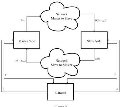
The main software component is called E-Board and interacts with the physical board by using theSOEM library [19]. Each side of the teleoperation architecture is represented by a logical abstraction of the control and of the DC motor and are indicated with Master SideandSlave Sidein Figure 9. Both components receive the current angular positions from the board and send voltage commands to the mo- tors’ amplifiers. The master and slave sides exchange control/measurement data through two instances of a component that simulates a network connection by de- laying and/or losing packets. The network component queues packets and assigns them a delay value. The delay can be constant or random; we implemented the following probability distributions: uniform (between an upper and lower bounds), Gaussian or exponential. When the current packet is received, the queue content is sorted according to the corresponding delay and the last valid packet is written to the output port. It is worth highlighting that in case of multiple packets with the same exit time (receiving time + communication delay), the queue is emptied of any packet with equal exit time and the one with the largest packet identifier (pktid) is sent out.
The state of master and slave is contained within astructtype calledDataStructure (indicated as “D” in Figure 9):
s t r u c t D a t a S t r u c t u r e {
u n s i g n e d i n t p k t i d ; c h a r s e n d e r ;
d o u b l e j o i n t ; d o u b l e v o l t a g e ; d o u b l e s p e e d ;
d o u b l e a b s o r b e d C u r r e n t ; d o u b l e t i m e s t a m p ;
d o u b l e g e n e r i c F i e l d 1 ; d o u b l e g e n e r i c F i e l d 2 ; d o u b l e g e n e r i c F i e l d 3 ; d o u b l e g e n e r i c F i e l d 4 ; };
TheGeneric Fieldswithin theDataStructureare needed to exchange further infor- mation between the master and slave sides according to the particular solution under study (e.g. wave variables, energy quanta).
6 Results
In this section we show some plots of data collected during the test and comparison of the algorithms.
Figure 9 Components organisation.
6.1 Force sensors tuning
Thetestbenchisequippedwithtwosingle-axisforcesensorsatthemasterandslave side. Someof thebilateralteleoperation algorithmsexplicitlyuse forcemeasure- ments to provide direct force feedback to the user, whereas others provide an indirect force feedback related to the displacement between master and slave positions. Thesecondsetofalgorithmsrequiresfewersensorsbutgenerates force feedbacktotheusereveniftheslaveisnotincontactwiththeenvironment.
An important step is to relate the measurement force to the motor torque and to the voltage command (ignoring the dynamics of the electrical subsystem). Figure 10 shows the linear interpolation relating voltages and force measurements. It is inter- esting to see that the force sensors have an important negative bias. Even though the sensors are the same, the slopes are different because of the gear ratio at the master side (N=4). Moreover there is a “dead zone” around zero. This is not due to the sensor but to the high static friction of the motors. Voltages below 0.5 V do not move the motors. These force sensors have also a rather high quantization error (around 0.15 N) that will be clearly visible in Section 6.2.
6.2 Experiments
Figure 11 shows the behavior of the algorithm described in Section 3.2 when the slave gets in contact with the environment (∼3.1s). The bilateral teleoperation sys- tem remains stable despite the communication delay and the hard contact. The
0 0.5 1 1.5 2 2.5 3 3.5
−1
−0.5 0 0.5 1 1.5 2 2.5 3 3.5
Voltage (V)
Force (N)
Master Slave
Figure 10
Calibration of the force sensors.
voltages at the master and slave side have very similar values (in absolute value but opposite signs) and are strongly correlated to the force measurements at the master side.
Afterthecontact,thepositionoftheslavedoesnotchangewhereasthe masterforce is proportional to the difference between the master and slave positions. The temporalmisalignmentthatcanbeseeninthemasterandslavevoltagesismainly duetotheroundtriptimeτm2s+τs2mandpartiallyonthehapticpaddledynamics andthecontrolparameters(Kp,KvandKdis,Pε). Highvaluesforτm2s,τs2mimplya highvalueforKdis: thesystembehavesinasluggishmanner. Thisisthepriceto paytohavethesystempassivewithhighroundtriptime.
The plots in Figure 12 show how the PSPM algorithm of Section 4.2 modulates the desired reference positionxsdwhen the energy levelEsis close to zero. In this case there is no contact but the instability arises due to the discretization and the fast movement compared with the energy shuffling and reharvesting. Any time there is a lack of energy (positive energy in the bottom plot in the figure) the minimization problem (25) determines the proper modulated reference position ¯xsd to satisfy the stability constraint.
Conclusions
In thispaper we reviewed classic andmore recentalgorithms that guarantee the stability ofbilateralteleoperationsystems.The crucialconcept ofpassivity isim- plementedineachalgorithmindifferentformstosafelyinteractwithunknownen- vironmentdespitecommunicationdelayfromthemasterandslavesides.Welistthe assumptionsbehindeachalgorithm,theiradvantagesanddisadvantages,andwe
2 3 4 5 6 7 8 9 10 0
2 4 6
Master Force (N)
2 3 4 5 6 7 8 9 10
0 1 2 3
Voltages (V)
Master (−) Slave
2 3 4 5 6 7 8 9 10
0 1 2 3
Position (rad)
time (s) Master
Slave
Figure 11
PD plus passivity terms. Hard Contact scenario,τm2s=τs2m=10ms,Fs=100Hz,Kp=1.0,Kv=0.02, Pε=0.001. The dashed vertical line around 3.1s is when the hard contact occurs.
highlightsomeimportantpointsthatadesignershouldtakeintoaccounttochose the best algorithmfor his/herapplications. Experimentalresults obtained bystu- dents of the AdvancedRobotics course, offered at the University of Verona, are alsoreportedtodemonstratethebehaviorofthedifferentalgorithms.
References
[1] ESA, http://esa-telerobotics.net/, (Access date: Dec 14, 2015).
[2] NASA, http://www.nasa.gov/, (Access date: Dec 14, 2015).
[3] Intuitive Surgical, http://www.intuitivesurgical.com, (Access date: Dec 14, 2015).
[4] T. B. Sheridan, “Space teleoperation through time delay: review and prog- nosis,” Robotics and Automation, IEEE Transactions on, vol. 9, no. 5, pp.
592–606, 1993.
42 42.5 43 43.5 44 44.5 45 45.5
−1.5
−1
−0.5 0 0.5 1
Position (rad)
Master Position Slave Reference Slave Position
42 42.5 43 43.5 44 44.5 45 45.5
0 0.1 0.2 0.3 0.4
Time (s)
Slave Energy (Joule)
Slave Energy
Figure 12
PSPM algorithm.τM2S=τS2M=10ms,Fsctrl=500Hz,Fsnetwork=100Hz,Kp=1.0,Kv=0.01.
[5] P. F. Hokayem and M. W. Spong, “Bilateral teleoperation: An historical sur- vey,”Automatica, vol. 42, no. 12, pp. 2035–2057, 2006.
[6] E. Nu˜no, L. Basa˜nez, and R. Ortega, “Passivity-based control for bilateral teleoperation: A tutorial,”Automatica, vol. 47, no. 3, pp. 485–495, 2011.
[7] Aliaga, I., A. Rubio, and E. Sanchez, “Experimental quantitative compari- son of different control architectures for master-slave teleoperation,”Control Systems Technology, IEEE Transactions on, vol. 12, no. 1, pp. 2–11, 2014.
[8] De Gersem, G., H. Van Brussel, and F. Tendick, “Reliable and enhanced stiff- ness perception in soft-tissue telemanipulation,”The International Journal of Robotics Research, vol. 24, no. 10, pp. 805–822, 2005.
[9] Malysz, P. and S. Sirouspour, “Nonlinear and filtered force/position map- pings in bilateral teleoperation with application to enhanced stiffness dis- crimination,”,Robotics, IEEE Transactions on, vol. 25, no. 5, pp. 1134–1149, 2009.
[10] D. Lawrence, “Stability and transparency in bilateral teleoperation,”Robotics and Automation, IEEE Transactions on, vol. 9, no. 5, pp. 624–637, 1993.
[11] G. Niemeyer and J.-J. E. Slotine, “Stable adaptive teleoperation,” Oceanic Engineering, IEEE Journal of, vol. 16, no. 1, pp. 152–162, 1991.
[12] D. Lee and M. W. Spong, “Passive bilateral teleoperation with constant time delay,”Robotics, IEEE Transactions on, vol. 22, no. 2, pp. 269–281, 2006.
[13] N. Chopra, M. W. Spong, and R. Lozano, “Synchronization of bilateral tele- operators with time delay,”Automatica, vol. 44, no. 8, pp. 2142–2148, 2008.
[14] J.-H. Ryu, J. Artigas, and C. Preusche, “A passive bilateral control scheme for a teleoperator with time-varying communication delay,” Mechatronics, vol. 20, no. 7, pp. 812–823, 2010.
[15] D. Lee and K. Huang, “Passive-set-position-modulation framework for inter- active robotic systems,”Robotics, IEEE Transactions on, vol. 26, no. 2, pp.
354–369, 2010.
[16] M. Franken, S. Stramigioli, S. Misra, C. Secchi, and A. Macchelli, “Bilateral telemanipulation with time delays: A two-layer approach combining passiv- ity and transparency,” Robotics, IEEE Transactions on, vol. 27, no. 4, pp.
741–756, 2011.
[17] OROCOS, http://www.orocos.org, (Access date: Dec 14, 2015).
[18] RTnet, http://www.rtnet.org/, (Access date: Dec 14, 2015).
[19] SOEM, http://openethercatsociety.github.io/, (Access date: Dec 14, 2015).