Függelék
9) opponensi megjegyzésre adott válaszhoz
Acta Cybernetica20(2011) 5–15.
A Stochastic Approach to Improve Macula Detection in Retinal Images
B´ alint Antal and Andr´ as Hajdu
∗Abstract
In this paper, we present an approach to improve detectors used in med- ical image processing by fine-tuning their parameters for a certain dataset.
The proposed algorithm uses a stochastic search algorithm to deal with large search spaces. We investigate the effectiveness of this approach by evaluating it on an actual clinical application. Namely, we present promising results with outperforming four state-of-the-art algorithms used for the detection of the center of the sharp vision (macula) in digital fundus images.
Keywords: biomedical image processing, simulated annealing, learning and adaptive systems
1 Introduction
Diabetic Retinopathy (DR) is the most common cause of blindness in the developed countries. Nowadays, the automatic screening of DR received much attention in the medical imaging community [1], [7], [9], since replacing a resource-demanding and expensive manual screening is a very challenging task. Automatic screening is based on the analysis of retinal images taken at eye hospitals. One class of the difficulties originates from the use of different kinds of retinal images, which leads to varying performance in the anatomy or lesion detection processes. Some detectors are based on machine learning, while others consider non-training approaches.
In this paper, we present a technique to improve a detection algorithm on retinal images via a learning-based approach. The idea behind this technique is to fine- tune the parameter setup for a certain detector. Since the selection of the optimal parameter setup usually traverses a large search space, we decided to use a stochas- tic approach, simulated annealing for this task. To demonstrate the effectiveness of this technique, we present a novel macula detector and show that the proposed framework improves detection performance. The contribution in this particular area is justified by the fact that the detection of macula involves the lowest number of reported works in the field of DR screening research [16]. A comparative analysis
∗University of Debrecen, Hungary. E-mail:{antal.balint, hajdu.andras}@inf.unideb.hu
DOI: 10.14232/actacyb.20.1.2011.2
6 B´alint Antal and Andr´as Hajdu
reveals that our tuned algorithm outperforms other state-of-the-art algorithms in the field.
The main contributions of the paper are organized into the following sections:
1. A stochastic approach to improve detector performance is introduced. We also discuss the advantages of using simulated annealing over stochastic hill climbing (Section 2).
2. We show how to adopt the simulated annealing based search method to im- prove the performance of the proposed macula detector (Section 3).
3. A novel macula detector is proposed, which, in addition to its good perfor- mance, can be easily fine-tuned by a search algorithm (Section 3.1).
4. We define an error measure to efficiently characterize macula detection per- formance (Section 3.3).
5. We evaluate the performance of our macula detector using the proposed tun- ing also in comparison with four state-of-the-art algorithms (Section 4).
2 A stochastic approach to improve detector per- formance
In this section, we present our approach to select an optimal parameter setup for a detector algorithm. For this task, we have to prepare for a large search space, since these algorithms may operate with several parameters. In literature, stochastic hill climbing is often recommended [10] [13]. Stochastic hill climbing is based on the idea that using random jumps between the neighbouring elements of the search space converges faster to the extrema than using exhaustive enumerations. An element is accepted, if it provides better result than the current extremum. This approach is an effective solution for many problems, but it can get stuck in a local extrema in search spaces with many peaks.
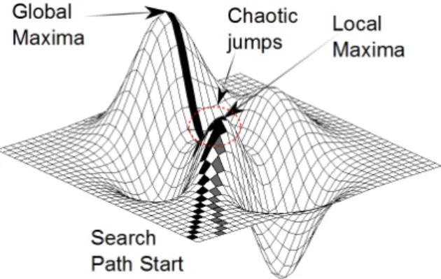
To overcome this difficulty, we used a simulated annealing-based method. Sim- ulated annealing [5] avoids getting stuck in local extrema by using a random ac- ceptance function for rejected elements. That is, if an element does not provide a better result than the current one, it is still accepted if the acceptance function allows that. See Figure 1 for a visual comparison of hill climbing and simulated annealing.
The formal description of the algorithm can be given as follows:
Algorithm 1.: Parameter setup selection by simulated annealing.
Input:
• An initial temperatureT ∈R.
• A minimal temperature Tmin ∈R.
A Stochastic Approach to Improve Macula Detection in Retinal Images 7
Figure 1: The path of the hill climbing and the simulated annealing algorithm is represented with gray and black colors, respectively. While hill climbing reaches only the local optimum, simulated annealing can continue towards the global opti- mum by using chaotic jumps.
• A temperature changeq∈Rwith (0≤q≤1).
• A search spaceS⊂Rn withs∈S is a parameter setup.
• A functionr(X), which chooses a random elementxfrom a setX.
• A functionaccept:R4→ {true, f alse}, which is defined as the follows:
accept(e, ei, T, y) =
(true, if exp e−eTi
> y, f alse, otherwise.
• An energy functionE:S →R.
Output: soptimal ∈ S, where E(soptimal) = min
s∈SE(s). That is, soptimal is the parameter setup minimizing the energy functionE.
1. s←r(S)
2. e←E(s)
3. S←S− {s}
4. while S6=∅orT < Tmin do
5. si←r(S)
6. ei←E(si)
7. S←S− {si}
8. if ei< ethen
9. s←si
8 B´alint Antal and Andr´as Hajdu
10. e←ei 11. T ←T·q
12. else
13. y←r(R)
14. if accept(e, ei, T, y) =truethen
15. s←si
16. e←ei
17. T ←T·q
18. end if
19. end if
20. end while
21. return s
3 Using the proposed approach: an example
In this section, we present an example to demonstrate the power of the proposed method. For this task, we chose a novel approach for macula detection in retinal images, which algorithm requires only two parameter to be optimized. Our pro- posed approach for obtaining the optimal parameter setup can be adapted to any similar problem, as well.
3.1 Macula detection
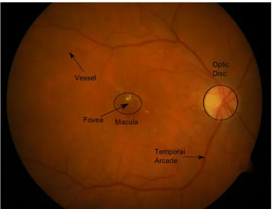
The macula is the central region of sharp vision in the human eye, with its center referred to as the fovea (see Figure 2). Any lesions (e.g. microaneurysms) which appear here can lead to severe loss of vision. Therefore, the efficient detection of the macula is essential in an automatic screening system for diabetic retinopathy.
3.2 A novel algorithm for macula detection
In this section, we present a novel approach to detect macula in a retinal image. As we can see later on, this algorithm outperforms state-of-the-art macula detectors with the use of the proposed framework for optimal parameter setup.
The proposed macula detection algorithm can be formulated as follows:
Algorithm 2.: A novel macula detector Input:
• A digital retinal imageI in 24 bitRGBformat.
• A parameterq∈Rwith 0≤q≤1 to adjust of the mask size in the median filtering step.
• A thresholdt∈[−255, . . . ,255].
A Stochastic Approach to Improve Macula Detection in Retinal Images 9
Figure 2: A sample fundus image with the main anatomical parts annotated.
Output: An image containing the macula region of the eye.
1. Extract the green intensity channelGfromI.
2. LetA=dM in(width(I), height(I))·qe.
3. Produce image M with the same size asGby applying median filtering [12]
onGwith a mask sizeA×A.
4. Create the difference imageD=G−M.
5. Produce a binary imageB by assigning all pixels with larger intensity thant in theD to the foreground, while the rest to its background.
6. Select the largest binary component to locate the macula.
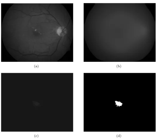
The results after each step of the algorithm can also be observed in Figure 3.
10 B´alint Antal and Andr´as Hajdu
(a) (b)
(c) (d)
Figure 3: Steps of the proposed macula detection: (a) The green channel of the input image. (b) The result of the median filtering. (c) The difference image. (d) The binary image after thresholding and largest component selection.
3.3 Error measurement of macula detectors
To select the optimal parameter setup for the above detector algorithm, we need a proper energy function to be minimized. An obvious choice for this task is to minimize the distance of the centroid of the macula found by the detector and the manually selected center of the macula for each image in a dataset. To avoid overtraining, we also take into account the distance from the optic disc (see Figure 2), as the macula and the optic disc are spatially constrained [11].
Thus, we define the following energy function for this problem:
E= X
I∈DS
d(Malg(I), Mhm(I)) + X
I∈DS
|d(Malg(I), O)−M Oavg|,
where
A Stochastic Approach to Improve Macula Detection in Retinal Images 11
• DS is the dataset,
• ddenotes the 2D Euclidean distance,
• Malg is the centroid pixel of the detected macula,
• Mhmis the manually selected macula center,
• O is the manually selected optic disc center,
• M Oavg is the average Euclidean distance of the manually selected macula and optic disc center for the datasetDS.
4 Comparative results
We evaluate our method by comparing it with four other state-of-the-art macula detectors (Section 4.1) on different datasets (Section 4.2). As our results will show, the novel macula detector outperforms the others after finding its optimal param- eter setup.
4.1 State-of-the-art macula detection algorithms
In this section, we list four macula detection algorithms, which are involved in our comparative analysis. The parameters of the algorithms were set according to the corresponding recommendations in literature.
4.1.1 Petsatodis et al. [8]
In [8] a region of interest (ROI) is defined to process macula detection. A Gaussian low-pass filter is applied to smooth the image. The statistical mean and standard deviation of the ROI area are used to compute a threshold for segmentation to get binary objects. The object that is located nearest to the center of the ROI is labelled as macula. Its center of mass is considered to be the center of the macula.
However, we did some modification to this approach, because it is not mentioned how this ROI is defined; therefore we applied the smoothing to the whole image using a large kernel (70×70 pixels with σ = 10) so that vascular network and small patches do not interfere in detection. Then, an iterative thresholding process is launched to generate a set of binary images corresponding to different threshold values. In each binary image, the component satisfying the area and distance from the center constraints are identified, and the component found nearest to the center with minimum area is marked as macula.
4.1.2 Sekhar et al. [11]
In [11] a region of interest (ROI) for macula is defined regarding its spatial rela- tionship to the optic disc. That is the portion of a sector subtended at the center of the optic disc by an angle of 30◦ above and below the line between this center and
12 B´alint Antal and Andr´as Hajdu
the center of the retinal image disc. The macula is identified within this ROI by iteratively applying a threshold, and then applying morphological opening (erosion followed by dilation) on the resulting blob. The value of the threshold parameter is selected such that the area of the smoothed macula region is not more than 80%
of that of the detected optic disc. The fovea is simply determined as the centroid of this blob.
4.1.3 Fleming et al. [2]
Fleming et al. [2] proposed to identify the macular region based on the informa- tion of the temporal arcade and OD center. First, the arcade is found by using semielliptical templates. Next, the optic disc is detected by using Hough trans- formation with circular templates having diameters from 0.7 to 1.25 OD diameter (DD). Finally, the fovea was detected by finding the maximum correlation coeffi- cient between the image and a foveal model. The search was restricted to a circular region with diameter 1.6 DD centered on a point that is 2.4 DD from the optic disc and on a line between the detected optic disc and the center of the semi-ellipse fitted to the temporal arcades.
4.1.4 Zana et al. [17]
Zana et al. [17] presented a region merging algorithm based on watershed cell decomposition and morphological operations for macula recognition. After noise removal, morphological closing followed by opening is performed to remove the small dark holes and white spots. A watershed based decomposition of the gradient image into cells is done, and the cell with darkest gray level inside the macula is selected as the first step of a merging algorithm. A complex criterion based on the gray values and of edges of the filtered image is calculated to merge the cells of the macula, while rejecting perifoveal inter-capillary zones in order to produce the contour of the macula.
4.2 Datasets
We have tested our approach on 199 images from three publicly available data sources: DiaretDB0 [3], DiaretDB1 [4] and DRIVE [15]. The characteristic prop- erties of these datasets can be seen in Table 1. We have selected the optimal parameter setup for each dataset using a separate training subset of a total of 60 images (20 images from each dataset). For each dataset, the ground truth are used only for parameter selection.
4.3 Results
Table 2 shows the selected optimal parameters for each dataset. The size param- eterq and the threshold parametert have been found by the proposed stochastic approach. Each dataset performed optimally using a different parameter setup.
We have evaluated our approach in two aspects [6]: whether the detected macula
A Stochastic Approach to Improve Macula Detection in Retinal Images 13
Dataset Images Normal DR FOV Resolution
DiaretDB0 130 20 110 50 1500x1152
DiaretDB1 89 5 84 50 1500x1152
DRIVE 40 33 7 45 768x584
Table 1: Properties of the datasets.
Dataset q t
DiaretDB0 0.6 0 DiaretDB1 0.6 5
Drive 0.7 0
Table 2: Parameters selected by the proposed algorithm for macula detection.
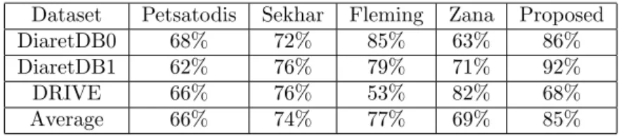
center falls into the 0.5DD (Optic Disc Diameter) distance of the manually selected macula center and we also measured the Euclidean distance of them (calculated on normalized images). Table 3 and 4 contain the quantitative results using these mea- sures, respectively. We disclose the results for each macula detector evaluated in all dataset. For the more straight-forward comparison, we also calculated the simple average of these performance values. In the terms of the first measure, the use of the proposed algorithm on the novel macula detector resulted in a 85% average accuracy, while the second best method only earned 77%. However, in the terms Euclidean error it is only third in the comparison, mainly because of its difficulties on the DRIVE database.
Dataset Petsatodis Sekhar Fleming Zana Proposed
DiaretDB0 68% 72% 85% 63% 86%
DiaretDB1 62% 76% 79% 71% 92%
DRIVE 66% 76% 53% 82% 68%
Average 66% 74% 77% 69% 85%
Table 3: Percentage of detected macula centers falling in the correct region.
5 Conclusion
In this paper, we have presented an approach to improve detection algorithms by fine-tuning their parameters. For this task, we have used a simulated annealing- based search algorithm. As our experiments have proved, this approach is capable of improving a detector that outperforms state-of-the-art algorithms in the field of macula detectors. As a future work, the selection of different preprocessing methods for the dataset can further improve the detection of the macula. In addition, both simulated annealing [14] and the proposed detector could be implemented in parallel to reduce their computational needs.
14 B´alint Antal and Andr´as Hajdu
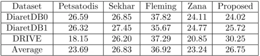
Dataset Petsatodis Sekhar Fleming Zana Proposed DiaretDB0 26.59 26.85 37.82 24.11 24.02 DiaretDB1 26.32 27.45 35.67 24.77 25.72
DRIVE 18.15 26.20 37.29 20.85 30.25
Average 23.69 26.83 36.92 23.24 26.75
Table 4: Average euclidean distance of the detected macula centers from the man- ually selected ones.
Acknowledgement
This work was supported in part by the J´anos Bolyai grant of the Hungarian Academy of Sciences, and by the TECH08-2 project DRSCREEN - Developing a computer based image processing system for diabetic retinopathy screening of the National Office for Research and Technology of Hungary (contract no.: OM- 00194/2008, OM-00195/2008, OM-00196/2008). We also acknowledge the Moore- fields Eye Hospital, London for their clinical support. We are thankful to Brigitta Nagy and Ign´ac Cs˝osz for their technical assistance.
References
[1] Abramoff, M. D., Reinhardt, J. M., Russell, S. R., Folk, J. C., Mahajan, V. B., Niemeijer, M., and Quellec, G. Automated early detection of diabetic retinopathy. Ophthalmology, 117(6):1147–1154, 2010.
[2] Fleming, A. D., Philip, S., Goatman, K. A., Olson, J. A., and Sharp, P.F.
Automated assessment of diabetic retinal image quality based on clarity and field definition.Investigative Ophthalmology and Visual Science, 47:1120–1125, 2006.
[3] Kauppi, T., Kalesnykiene, V., Kamarainen, J.K., Lensu, L., Sorri, I., Uusi- talo, H., Kalviainen, H., and Pietila, J. Diaretdb0: Evaluation database and methodology for diabetic retinopathy algorithms. Technical report, Lappeen- ranta University of Technology, Lappeenranta, Finland, 2006.
[4] Kauppi, T., Kalesnykiene, V., Kmrinen, J.K., Lensu, L., Sorri, I., Raninen, A., Voutilainen, R., Uusitalo, H., Klviinen, H., and Pietil, J. Diaretdb1 diabetic retinopathy database and evaluation protocol. Proc. of the 11th Conf. on Medical Image Understanding and Analysis (MIUA2007), pages 61–65, 2007.
[5] Kirkpatrick, S., Gelatt, C. D., and Vecchi, M. P. Optimization by simulated annealing. Science, 220:671–680, May 13, 1983.
[6] Kovacs, L., Qureshi, R.J., Nagy, B., Harangi, B., and Hajdu, A. Graph based detection of optic disc and fovea in retinal images. InSoft Computing Appli- cations (SOFA), 2010 4th International Workshop on, pages 143–148, 2010.
A Stochastic Approach to Improve Macula Detection in Retinal Images 15
[7] Niemeijer, M., van Ginneken, B., Cree, M.J., Mizutani, A., Quellec, G., Sanchez, C.I., Zhang, B., Hornero, R., Lamard, M., Muramatsu, C., Wu, X., Cazuguel, G., You, J., Mayo, A., Li, Q., Hatanaka, Y., Cochener, B., Roux, C., Karray, F., Garcia, M., Fujita, H., and Abramoff, M.D. Retinopathy on- line challenge: Automatic detection of microaneurysms in digital color fundus photographs. IEEE Transactions on Medical Imaging, 29(1):185–195, 2010.
[8] Petsatodis, T. S., Diamantis, A., and Syrcos, G. P. A complete algorithm for automatic human recognition based on retina vascular network character- istics. Era1 International Scientific Conference, Peloponnese, Greece, 16-17 September 2006.
[9] Ravishankar, S., Jain, A., and Mittal, A. Automated feature extraction for early detection of diabetic retinopathy in fundus images. In CVPR, pages 210–217. IEEE, 2009.
[10] Ruta, D. and Gabrys, B. Classifier selection for majority voting. Information Fusion, 6(1):63 – 81, 2005. Diversity in Multiple Classifier Systems.
[11] Sekhar, S., Al-Nuaimy, W., and Nandi, A. K. Automated localization of op- tic disc and fovea in retinal fundus images. 16th European Signal Processing Conference, Lausanne, Switzerland, 2008.
[12] Sinha, P. K. and Hong, Q. H. An improved median filter. IEEE Transactions on Medical Imaging, 9(3):345–346, 1990.
[13] Sivanandam, S. N. and Deepa, S. N. Introduction to Genetic Algorithms.
Springer, 2008.
[14] So, O. and ¨Ozdamar, L. Parallel Simulated Annealing Algorithms in Global Optimization. Journal of Global Optimization, 19:27–50, 2001.
[15] Staal, J., Abramoff, M. D., Niemeijer, M., Viergever, M. A., and van Gin- neken, B. Ridge-based vessel segmentation in color images of the retina.IEEE Transactions on Medical Imaging, 23:501–509, 2004.
[16] Winder, R.J., Morrow, P.J., McRitchie, I.N., Bailie, J.R., and Hart, P.M.
Algorithms for digital image processing in diabetic retinopathy.Computerized Medical Imaging and Graphics, 33(8):608–622, 2009.
[17] Zana, F., Meunier, I., and Klein, J. C. A region merging algorithm using mathematical morphology: application to macula detection. In ISMM ’98:
Proceedings of the fourth international symposium on Mathematical morphol- ogy and its applications to image and signal processing, pages 423–430, Norwell, MA, USA, 1998. Kluwer Academic Publishers.
EXTRACTION OF VASCULAR SYSTEM IN RETINA IMAGES USING AVERAGED ONE-DEPENDENCE ESTIMATORS AND ORIENTATION ESTIMATION IN HIDDEN
MARKOV RANDOM FIELDS Gy¨orgy Kov´acs, Andr´as Hajdu
University of Debrecen Faculty of Informatics 4010, POB 12, Debrecen, Hungary
ABSTRACT
The proper segmentation of the vascular system of the retina currently attracts wide interest. As a precious outcome, a suc- cessful segmentation may lead to the improvement of auto- matic screening systems. Namely, the detection of the ves- sels helps the localization of other anatomical parts and le- sions besides the vascular disorders. In this paper, we rec- ommend a novel approach for the segmentation of the vascu- lar system in retina images, based on Hidden Markov Ran- dom Fields (HMRF). We extend the optimization problem of HMRF models considering the tangent vector field of the im- age to enhance the connectivity of the vascular system con- sisting of elongated structures. To enhance the probability es- timation during the solution of the Hidden Markov problem, the Averaged One-Dependence Estimator (AODE) is used in- stead of the commonly used naive Bayes estimators, since AODE uses a weaker assumption than total independence of features. The advantages of our method is discussed through a quantitative analysis on a publicly available database.
Index Terms— averaged one-dependence estimator, hid- den markov fields, retina, vessel
1. INTRODUCTION
Algorithms for segmenting the vascular system of the retina have high importance in automatic systems for detecting dis- eases (such as diabetic retinopathy) based on digital fundus images. One of the most reliably detectable anatomical parts even for low quality images is the vascular system, because there are no similar lesions on the retina. Using an accu- rately segmented vascular system, we have better chances to locate other anatomical parts (e.g. optic disc and fovea) of the retina and explore the disorders of the vascular system itself. The extraction of the vascular system is a rather com- plex task, knowing only that the vascular system has lower intensity than its background and the widths of the vessels are varying. Motivated by its importance, several vessel seg- mentation approaches can be found in the literature including intensity edges [1], adaptive thresholding [2], region growing
[3], mathematical morphology [4], machine learning [5], en- semble learning [6]. In this paper we propose a novel vascu- lature segmentation approach based on Hidden Markov Ran- dom Fields (HMRF). HMRF is a popular approach for the statistical segmentation of images. The segmentation process means the maximization of an energy functional defined on the set of all possible labelings of the image, where the global maximum of the energy functional belongs to the best seg- mentation according to the image model. HMRF-based vas- cular system extraction of the retina has already been sug- gested in [7]. This method considers angiographic retinal im- ages as input, where the appearance of the vessel system is much more defined than in normal fundus images. However, the usage of angiography is not allowed for the state-of-the-art automatic screening systems and the method presented in [7]
gives poor results fo normal retinal images. In the commonly used form of the HMRF based segmentation, the background and foreground probability estimations are performed by con- inuous naive Bayesian estimation[8], based on the continuous model extracted from the training data. In the segmentation of color images this approach performs well, however using features extracted from intensity images, like the green chan- nel of retinal images, the assumption that the distribution of features is Gaussian or Mixture of Gaussians and the coor- dinates of the feature vectors are independent, seems to be too strong, smoothing the boundaries of classes in the fea- ture space. To overcome this problem, we have integrated the averaged one-dependence estimator (AODE) [9] into our segmentation model, which does not have the assumption of Gaussian feature distributions and total independence of fea- ture coordinates. The use of AODE estimators has not yet been reported in HMRF segmentation models. To enhance the segmentation of thin vessels, we have trained the AODE model for three classes: background, thin vessels and thick vessels, but during the segmentation, the latter two classes are considered to be one class. Since HMRF is a general ap- proach that does not consider orientation information at the pixels in its basic formulation, we integrate a corresponding new term into the model. However, instead of following the
693
978-1-4244-4128-0/11/$25.00 ©2011 IEEE ISBI 2011
classic way with using the local gradients directly, first we determine the structure tensor field from them. Then, the ten- sor field is smoothed and weighted and the local tangents are estimated as the eigenvectors corresponding to the smaller eigenvalues of the tensors. This approach leads to a more reliable estimation of the vessel directions that helps to pre- serve the connectivity of the vascular system during segmen- tation. The rest of the paper is organized as follows. Section 2 describes the steps of our proposed method. In Section 3 we exhibit our experimental results on the publicly available database DRIVE [10] and compare the results to a state-of- the-art method. Finally in Section 4, some conclusions are drawn.
2. THE PROPOSED METHOD
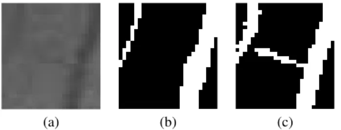
The input of our algorithm is the RGB retina image, the output is a label image containing two labels: vessel, back- ground. For the training of the segmentation model, the DRIVE database is prepared by applying simple morpholog- ical operators to isolate thick and thin vessels. In Figure 1 a sample from the training database, the corresponding manu- ally labeled mask and the extracted thick and thin vessels can be seen, respectively.
(a) (b) (c) (d)
Fig. 1. Retina image from the training set (a), its standard manual labeling (b), the extracted thin (c) and thick (d) vessels LetI ∈[0..255]m×nbe an intensity image (in our case the green channel, since mainly the green channel contains infor- mation about the vascular system) andL ∈ {f g, bg}m×na possible labeling of the input image. The HMRF based seg- mentation means the maximization of the functional
E(I, L) =
i,j
P(L(i, j)|I(i, j)) +
i,j
CD(L, i, j), (1)
whereP is the conditional probability of the(i, j)pixel be- longing to theL(i, j)class andCD(L, i, j)measures the con- nectivity of the labeling in the(i, j)position. The maximiza- tion of the functional is performed by simulated annealing.
2.1. Probability term
The first term of the energy functionalEestimates the proba- bility ofLbeing the most appropriate labeling ofI. The more accurate probability estimation we use, the more accurate the
segmentation becomes. Since the distribution of the features we use to characterize the pixels and their neighborhood usu- ally does not follow Gaussian distribution, we have chosen discrete classifiers. The drawback of the commonly used dis- crete naive Bayesian classifier is that it considers the corre- lation of one feature and the class label independently from other features, that is it assumes the total independence of features. The averaged one-dependence estimator (AODE), published in 2002 [9] considers the joint probabilities of every pair of features, as well. Therefore, the probability estimation becomes more accurate, but the computation demand is still a fraction of that of multivariate Bayesian classification.
LetY be the set of class labels andX ⊂Zdbe a set ofd dimensional discrete feature vectors with
{xi|x∈X}
{xj|x∈X}=∅, 1≤i, j≤d, i=j. (2) The training of the AODE classifier means the maintenance of a two dimensional Pˆ(y, xi) and a three dimensional Pˆ(y, xi, xj) joint frequency table. The probability of the d-dimensional feature vectorxˆbelonging to the classy can be estimated by the following formula:
Pˆ(y|ˆx) =
iPˆ(y,xˆi)
jPˆ(ˆxj|y,xˆi)
y∈Y
iPˆ(y,xˆi)
jPˆ(ˆxj|y,xˆi). (3)
(a) (b)
(c) (d)
Fig. 2. Test image (a), standard manual segmentation (b), orientation field (c), HMRF-segmentation (d)
694
2.2. Connectivity term
The connectivity term of the HMRF optimization problem tries to quantitatively characterize the connectivity of the la- beling to avoid the fragmented segmentation results based on the probability term only. In the classic model of HMRF, 4- connectivity is preferred:
C(L, i, j) = −(d(Li,j, Li+1,j) +d(Li,j, Li−1,j)+
d(Li,j, Li,j+1) +d(Li,j, Li,j−1))∗β, (4) whered(l1, l2) = 1if thel1andl2labels are equivalent. Oth- erwise,d(l1, l2) = 0. βis a penalty parameter of the objec- tive functionalE, used to control the connectivity property.
Since thin vessels have fine structure of 1 pixel width, this commonly used connectivity term is a rough constraint on the final segmentation. To enhance this component, we have de- veloped the direction dependent connectivity termCD, where the connectivity is examined and penalized only in the di- rection of the strongest tangents in the neighborhood of each pixel(i, j):
CD(L, i, j) = −(d(Li,j, Li+tx(I,i,j),j+ty(I,i,j))+
d(Li,j, Li−tx(I,i,j),j−ty(I,i,j))∗β, (5) wheretx(I, i, j)andty(I, i, j)are the estimation of thexand ycomponents of the strongest tangent in the local neighbor- hood of(i, j), respectively:
tx(I, i, j) =
1, ifA(I)i,j< 3∗π8 orA(I)i,j> 5∗π8 ,
0, otherwise, (6)
ty(I, i, j) =
1, ifA(I)i,j > π8 andA(I)i,j< 7∗π8 ,
0, otherwise, (7)
whereA(I) is the estimation of the main tangent angels in each pixel(i, j)ofI. For the estimation ofA, we have com- puted the structure tensor fieldST Fof the imageI, assigning a2×2sized matrix to each pixel:
ST Fi,j=
G2xi,j Gxi,j∗Gyi,j Gxi,j∗Gyi,j G2yi,j
, (8)
whereGxi,jandGyi,jare the respectivexandycomponents of the gradient at pixel(i, j), estimated by the commonly used Sobel-operators. The tensor field is then weighted by the edge magnitudes and convolved by a Gaussian mask to provide smooth estimates:
SF Tsmoothedi,j =G(σ, k)∗(Ti,j(G2xi,j+G2yi,j)μ2). (9) This step is similar to the step of smoothing the orientation information in the scale-invariant feature transform (SIFT).
Using this smoothed tensor field the estimation of object tan- gent directions comes as
A(I)i,j=tan−1 Exi,j Eyi,j
, (10)
whereEis the vector field containing the eigenvector belong- ing to the smallest eigenvalue ofSF T, elementwise. In Fig- ure 2, one test image and the orientation field can be seen, the latter one represented by spikes.
(a) (b)
(c) (d)
Fig. 3. Convolution based MLSF (a), correlation based MLSF, matched Gabor filter magnitude (c), adaptive local contrast enhancement (d)
3. RESULTS
The proposed method is trained on the training set and tested on the testing set of the publicly available DRIVE database.
In the training phase, 200 features (eccentricity, invariant im- age moments, central moments, matched line segment filters using convolution and correlation, matched Gabor filters, and the result of several contrast enhancement methods with var- ious parametrizations) have been extracted for each pixel in the database and after forward feature subset selection, the fi- nal AODE classifier is trained on the features providing the best accuracy (in our case matched line segment filters using correlation and convolution, Gabor filters and the result of the adaptive local contrast enhancement with three parameteri- zation). In Figure 3, four feature images of the six selected features can be seen. To enhance the recognition of thin struc- tures, we have used three classes in the training process, but in the segmentation process the thin and thick vessel labels are considered to be equivalent. Using only the AODE classifier the accuracy became 93.7%, but the result is noisy. Keeping only the largest connected component, the accuracy decreases
695
to 85.3%. See Figure 2. Using the HMRF-based segmen- tation with orientation estimation and directional connectiv- ity term, the result becomes less noisy and after extracting the largest connected component, the accuracy increases to 91.2%. The specificity of the HMRF-based segmentation be- comes 89.8% alghough several thin vessels are not labeled on the manually segmented images but labeled by our method.
In Figure 4 one part of the same test image is highlighted, in which the thin and low contrast vessel found by our method is not labeled in the manual annotation available as part of the DRIVE database. The state-of-the-art method published by Oost et al. [6] reached 88.5% accuracy and 93.6% specificity, on the same database. See Figure 2 for the standard manual labeling and the HMRF segmentation of a test image.
(a) (b) (c)
Fig. 4. A really thin and low contrast vessel on the test image (a), its standard manual labeling (b), and the segmentation of the proposed method.
4. SUMMARY
The proposed method delegates several new approaches into the field of segmentation of vascular system in retinal images.
In the method we utilize the powerful AODE classifier which does not use the assumption of Gaussian distribution of fea- tures like many other classifiers and also weakens the strong assumption of naive Bayesian classifiers, i.e. the features are independent from each other. To increase the connectivity of the final segmentation, the classic HMRF model is extended with a direction dependent connectivity term. To increase ac- curacy, in the training database the thin and thick vessels are distinguished, but in the segmentation process, when the con- nectivity is examined, both of them is considered belonging to the same class. The overall method is straightforward, in- creasing the variety of extracted features, the accuracy and specificity of the segmentation may be increased further.
5. ACKNOWLEDGEMENTS
This work was supported in part by the Janos Bolyai grant of the Hungarian Academy of Sciences and by the TECH08- 2 project DRSCREEN - Developing a computer based im- age processing system for diabetic retinopathy screening of the National Office for Research and Technology of Hun- gary (contract no.: OM-00194/2008, OM-00195/2008, OM- 00196/2008).
6. REFERENCES
[1] A. Can, H. Shen, J. N. Turner, H. L. Tanenbaum, and B. Roysam, “Rapid automated tracing and fea- ture extraction from retinal fundus images using di- rect exploratory algorithms,” IEEE Trans. Inf. Technol.
Biomed., vol. 3, pp. 125–138, February 1999.
[2] X. Jiang and D. Mojon, “Adaptive local thresholding by verification-based multithreshold probing with applica- tion to vessel detection in retinal images,” IEEE Trans.
Pattern Anal. and Machine Intell., vol. 25, pp. 131–137, January 2003.
[3] M. E. Martinez-Prez, A. D. Hughes, A. V. Stanton, S. A.
Thom, A. A. Bharath, and K. H. Parker, “Retinal blood vessel segmentation by means of scale-space analysis and region growing,” in Medical Image Computing and Cmoputer-Assisted Intervention MICCAI99, 2003, vol. I, pp. 131–137.
[4] F. Zana and J. C. Klein, “Segmentation of vessel-like patterns using mathematical morphology and curvature evaluation,” IEEE Trans. Image Proc., vol. 10, pp.
1010–1019, July 2001.
[5] M. Niemeijer, J. J. Staal, B. van Ginneken, M. Loog, and M. D. Abramoff, “Comparative study of retinal vessel segmentation methods on a new publicly avail- able database,” SPIE Medical Imaging, vol. 5370, pp.
648–656, 2004.
[6] E. Oost, Akatsuka Y., A. Shimizu, H. Kobatake, D. Fu- rukawa, and A. Katayama, “Vessel segmentation in eye fundus images using ensemble learning and curve fit- ting,” in Biomedical Imaging: From Nano to Macro, 2010, IEEE International Symposium on. IEEE, 2010, pp. 676–679.
[7] A. Simo and E. de Ves, “Segmentation of macular flu- orescein angiographies: A statistical approach,”Pattern Recognition, vol. 34, pp. 128–139, April 2001.
[8] Carsten Rother, Vladimir Kolmogorov, and Andrew Blake, “Grabcut: Interactive foreground extraction us- ing iterated graph cuts,” ACM Transactions on Graph- ics, vol. 23, pp. 309–314, 2004.
[9] Geoffrey I. Webb, Janice Boughton, and Zhihai Wang,
“Averaged one-dependence estimators: Preliminary re- sults,” inUniversity of Technology Sydney, 2002, pp.
65–73.
[10] J. J Staal, M. D. Abramoff, M. Niemeijer, M. A.
Viergever, and B. van Ginneken, “Ridge based vessel segmentation in color images of the retina,”IEEE Trans.
Med. Imaging, vol. 23, pp. 501–509, April 2004.
696
MICROANEURYSM DETECTION IN RETINAL IMAGES USING A ROTATING CROSS-SECTION BASED MODEL
Istvan Lazar, Andras Hajdu
lazar.istvan@inf.unideb.hu, hajdu.andras@inf.unideb.hu
Faculty of Informatics, University of Debrecen, POB 12, 4010 Debrecen, Hungary
ABSTRACT
Retinal image analysis is currently a very vivid field in biomedical image analysis. One of the most challenging tasks is the reliable automatic detection of microaneurysms (MAs). Computer systems that aid the automatic detection of diabetic retinopathy (DR) greatly rely on MA detection.
In this paper, we present a method to construct an MA score map, from which the final MAs can be extracted by simple thresholding for a binary output, or by considering all the regional maxima to obtain probability scores. In contrary to most of the currently available MA detectors, the proposed one does not use any supervised training and classification.
However, it is still competitive in the field, with a prominent performance in the detection of MAs close to the vasculature, regarding the state-of-the-art methods. The algorithm has been evaluated in a publicly available online challenge.
Index Terms— Biomedical image processing, pattern recognition, microaneurysm detection, intensity profile
1. INTRODUCTION
Automated analysis of retinal (fundus) images has become a quite active field among ophthalmologists and researchers in digital image processing. One of the most important motivations is the need for an effective computer-aided diagnostic (CAD) system to recognize diabetic retinopathy
(DR). DR is the damage of the retina caused by diabetes. It is a sight-threatening disease that develops in most of the patients with long-standing illness. An automated DR screening system would be a great assist in the processes of diagnosing and progression tracking. Currently, these tasks are done by human graders who categorize each image manually according to the diagnosis protocol.
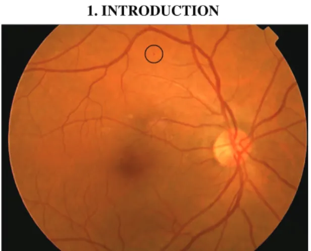
The presence of microaneurysms (MAs) in the retina is the earliest symptom of retinopathy, thus their reliable detection is essential in an automatic DR screening system.
MAs are circular dark spots, whose diameters are less than the diameter of the major optic veins. Figure 1 shows a retinal image with an MA marked. In this paper, we present a method for retinal MA detection, which in contrast to most of the existing algorithms does not require any training.
Still, it is able to precisely locate MAs with high sensitivity at low false positive rate. Moreover, it has an outstanding performance on lesions close to the vasculature regarding the state-of-the-art methods.
In section 2 we will briefly review the available algorithms for retinal MA detection, after which in section 3 the proposed method is described in details. In section 4, the results of our method in an open online challenge of MA detectors are presented.
2. STATE-OF-THE-ART MA DETECTORS
Most of the currently available methods divide MA detection into two consequent stages: candidate extraction and classification. Usually, the first step of candidate extraction is image preprocessing to reduce noise and improve contrast. After preprocessing, specific image segmentation is used to extract as much regions as possible that probably correspond to MAs. In the second step, the resulting candidates are labeled as true or false ones using a supervised learning based method. This classification requires a training set to establish the boundaries of the classes. The training set consists of pairs of feature vectors and class labels. Feature vectors are ordered sets of certain property values, mostly geometrical or color descriptors that may help to distinguish MAs from other objects. Such state of the art methods are proposed by e.g. Niemeijer et al. [1], Quellec et al. [2], and Zhang et al. [3].
Fig. 1. Retinal image with microaneurysm marked.
1405
978-1-4244-4128-0/11/$25.00 ©2011 IEEE ISBI 2011
Methods different from this two-phase approach have been also proposed. E.g. in [4] Giancdardo et al. presented a method based on Radon transformation that does not require explicit training.
3. THE PROPOSED METHOD
The method described in this paper is based on the two most characteristic attributes of MAs: diameter and circularity.
We will show that it is possible to construct a score-map that assigns a score value to every pixel in the image, where the dark small circular objects will achieve the highest scores, while the vessel structure almost completely disappears.
3.1. Preprocessing
The only actual parameter of the proposed algorithm is the maximal MA diameter (dmax). We consider this value as 7 pixels in the case of a horizontal resolution of 760 pixels for the visible retinal part. Thus, input images in different spatial resolution need to be rescaled. When working with a retinal image, the usual approach is to use its green channel, since it has the most useful information content. Though the proposed method does not require a specific preprocessing, a certain amount of noise reduction is necessary in most fundus images. We suggest the use of a simple two dimensional Gaussian blurring with a standard deviation of 1.4. Also, the input images are inverted, thus MAs and vessels will appear as bright structures. From now on, when referring to a retinal image, it is meant as the smoothened inverted green channel Isg of the original retinal image.
3.2. Cross-sectional profiles
Probably the most challenging task during automatic MA detection is the distinction between MAs and thin vessel fragments. Vessel segments are such structures in the retinal image whose points are local maxima in at least one direction. On the other hand, MAs are circular objects, thus they appear as local maxima from all directions.
To utilize this approach in practice, we need to test whether a pixel in the image is a local maximum in a particular direction. Therefore, we consider discrete line segments (scan lines) with different slopes, passing through the specific position being tested. The recordings of the pixel values along these scan lines result in a set of one dimensional intensity profiles, or in other words, in a set of cross-sectional profiles.
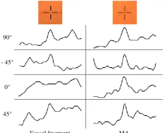
If we examine these profiles, we find that MAs show a definite peak for all directions. In the case of vessel points, only the profiles of scan lines perpendicular to the vessel show strong peaks, and as the direction of the scan line approximates the vessel segment, the peak on the profile becomes more and more elongated, until it almost completely disappears. Figure 2 shows the cross-section
profiles of a vessel segment and an MA point at different directions, respectively.
3.3 Scanning of the entire image
To exploit the observation about the cross-section profiles of MAs and vessel segments, every pixel of the image has to be accessed from every possible direction. For this reason we will use scan lines that pass through the entire image. Let us consider the slope-intercept equation ݕ ൌ ݉ ή ݔ ܾ of the line. By modifying the y-intercept parameter b at a fixed slope m, every pixel of the image can be accessed for that given m direction, except the vertical case which has to be handled separately. This way, we define the scan line ܵܮఈǡ, a point vector, whose ith element (ܵܮఈǡሾ݅ሿ) is the ith point of the discrete line defined by the ݕ ൌ ߙ ή ݔ ܾ equation.
That is,
ܵܮఈǡሾ݅ሿ ൌ ەۖ
۔
ۖۓെͻͲι ൏ ߙ ൏ െͶͷι ൬ඌ െ݅
ߙඐ ǡ ہܾۂ െ ݅൰ ǡ
െͶͷι ߙ Ͷͷι ሺ݅ǡ ہ ߙ ή ݅ ܾۂሻǡ Ͷͷι ൏ ߙ ൏ ͻͲι ൬ඌ ݅
ߙඐ ǡ ہܾۂ ݅൰ Ǥ The intensity profile of ܵܮఈǡ is defined as an integer valued vector, whose ith element is the intensity value of the image at the ܵܮఈǡሾ݅ሿ position. That is, ܫܲఈǡሾ݅ሿ ൌ ܫ௦൫ܵܮఈǡሾ݅ሿ൯. To handle the intensity profile of vertical scan lines, we define the VIPx vector, whose ith element is the intensity value of the image in the ith row and xth column. That is, ܸܫܲ௫ሾ݅ሿ ൌ ܫ௦ሺݔǡ ݅ሻ. As it can be seen from the definition of the scan lines, the possible directions cover 180°. Also, we specify that the scan directions have to be equidistantly sampled, i.e.:
ߙ א Ȱ ൌ ሼ߮ଵǡ ߮ଶǥሽ െͻͲι ൏ ߮ ͻͲι ר ߮ାଵെ ߮ ൌ ߱, 90°
- 45°
0°
45°
Vessel fragment MA
Fig. 2. Cross-section profiles of a vessel segment and an MA, respectively.
1406
where ߱ denotes the scan step parameter. Theoretically, choosing a small ߱ would result in a finer scanning.
However, our experiments showed that, choosing ߱ to be less than 3° will not make relevant difference in the final results. Figure 3 shows 4 examples of scan lines for different directions. The arrows represent the direction of the scanning.
3.4. Peak localization and height measurement
Since MAs appear as peaks on the intensity profiles of scan lines, the next step is to detect these peaks. In this case we have a width restriction to the peaks, that is, only those peaks whose width is less than or equal to dmax can correspond to MAs. Besides the position of the peaks, the measure of their height is also required, since this information describes how much the object is separated from its surroundings in a particular direction. Such measure is needed that will consider both the peak height and its width, that is, peaks that are wide will receive a lower value, even if their height would suggest otherwise. This requirement is fulfilled by applying area opening, a special type of attribute opening [5] on the intensity profiles. By considering the difference of the result and the original profile (top-hat transformation), we may obtain a proper corrected peak height measure for every position in the profile.
Attribute opening can be applied for both one and two dimensional data as well. It is based on the successive extension of all the regional maxima by progressively lowering the local threshold level, until a certain criterion becomes satisfied.
In the case of area opening, this halt condition is that the area of the extended region becomes larger than the given parameter. Let Ȟୟሺݒሻ denote the result of area opening applied to vector v with parameter Ȝ. This way, the area opening top-hat operator is defined as Ȟതതതሺݒሻ ൌ ݒ െ Ȟୟ ୟሺݒሻ.
Figure 4 shows the result of the attribute opening top-hat operator applied to an intensity profile with Ȝ = dmax. It can be seen, that the top-hat values give a proper measure of the peak height values along the profile.
3.5. Assigning a directional height value to every pixel
To assign a height value for a given direction to every pixel, we define the directional height map function ܦܪܯሺݔǡ ݕǡ ߙሻ, whose value is calculated as the corresponding value of the area opening top-hat operator applied to the intensity profile of the scan line that passes through the (x,y) point at an Į angle. That is,
ܦܪܯሺݔǡ ݕǡ ߙሻ ൌ ە
ۖ
۔
ۖ
ۓെͻͲι ൏ ߙ ൏ െͶͷι Ȟതതതതതതത൫ܫܲ ఈǡכ൯ሾہܾכۂ െ ݕሿǡ
െͶͷι ߙ Ͷͷι Ȟതതതതതതത൫ܫܲ ఈǡכ൯ሾݔሿǡ Ͷͷι ൏ ߙ ൏ ͻͲι Ȟതതതതതതത൫ܫܲ ఈǡכ൯ሾݕ െ ہܾכۂሿǡ
ߙ ൌ ͻͲι Ȟതതതതതതതሺ ܸܫܲݔሻሾݕሿǡ
where ܾכൌ ݕ െ ߙ ή ݔ. Let ܦܪܸሺݔǡ ݕሻ denote the vector containing the height values for a given position, i.e.:
ܦܪܸሺݔǡ ݕሻሾ݅ሿ ൌ ܦܪܯሺݔǡ ݕǡ ߮ሻ. Considering the DHV of an MA and a vessel point, we find that only MAs achieve nearly equal height values for all the scan directions, while in the case of vessel segments, there is a gap at the directions when the scan line fits the vessel segment. The DHV of an MA and a vessel point can be seen in Figure 5.
3.6. MA score map construction
Eventually, our goal is to create a score map, from which the MAs can be extracted by a simple thresholding for a binary output, or by considering all the regional maxima to obtain candidate points with the corresponding probability scores. We have several requirements regarding this map. It has to have high values for small circular objects (MAs), while the response to elongated structures (vessels) has to be minimal. Moreover, the response to MAs has to be proportionate to their strength.
We have seen that MAs have nearly equal height values for all scan directions. To obtain a measure of the proportion of directions in which the height value was larger Fig. 4. Top-hat result of attribute opening on an intensity profile.
MA
Vessel
-90° -45° 0° 45° 90°
Fig. 5. Plot of height values for an MA and a vessel point as the scan direction is rotating.
Fig. 3. Examples of scan lines with different directions.
1407
than a given h level to the number of all scan directions, we define the peak ratio map function PRMh, i.e.:
ܴܲܯሺݔǡ ݕሻ ൌȁߙ א Ȱ ܦܪܯሺݔǡ ݕǡ ߙሻ ݄ȁ
ȁȰȁ
PRMh has a value near to 1.0 in the case of MA points.
However, usually it has high values for vessels, especially for vessel crossings, as well. Figure 6 shows PRM6, the peak ratio map for height level 6 for the fundus image in Figure 1.
By applying a modified version of diameter opening top-hat operation on PRMh, vessels can be filtered out, and an MA probability image can be constructed for height level h. Diameter opening is a type of attribute opening, where the diameter of the extended region is tested. We apply two modifications. First, only those maximum regions have to be extended, where the PRMh of the seed point is near to 1.0, since only these regions correspond to MAs. Theoretically, this value should be always 1.0 in the case of circular objects. However, we found that, in practice, it is recommended to lower the seed threshold to e.g. 0.9. This limitation for the seed regions result in a faster execution, since most of the regional maxima can be ignored. Second, in the resulting top-hat, the extended regions are multiplied with the PRMh value of the corresponding seed. Let Ȟതതതሺܺሻ ఒௗ denote the result of this modified diameter opening tophat operation on image X, with parameter Ȝ. This way, we obtain the MA probability map at height level h, denoted as Ph, by applying Ȟതതതఒௗ on PRMh, i.e.:
ܲൌ Ȟതതതതതതതሺܴܲܯௗௗೌೣ ሻ.
To construct the final MA score map, which is independent from the height level parameter, we consider all possible Ph probability maps and combine them in a weighted pixelwise maximum selection. The value of each pixel in the final score map will be the product of the
maximal probability value among the probability maps, and the corresponding height level, i.e.:
ܵܿݎ݁ሺݔǡ ݕሻ ൌ ܲೌೣሺ௫ǡ௬ሻሺݔǡ ݕሻ ή ݄௫ሺݔǡ ݕሻ
݄௫ሺݔǡ ݕሻ ൌ ܽݎ݃݉ܽݔܲሺݔǡ ݕሻ,
where Score denotes the final MA score map. We found that it is sufficient to consider only the first 30 (h = {1 … 30}) probability maps. Moreover, the calculation of the Ph probability maps can be performed in parallel for the different h values, which gives a further boost to the method. The final MA score map of the fundus image in Figure 1 is shown in Figure 7. We can see that the highest score value was achieved by the strongest MA in the image.
4. EXPERIMENTAL RESULTS
To examine the performance of the proposed method in comparison with other state-of-the-art algorithms, we have submitted our results to the Retinopathy Online Challenge (ROC) [6]. To the best of our knowledge, currently ROC is the only possibility to compare MA detectors under the same conditions. This dataset consists of a training and a test set. Both sets contain 50 fundus images. The reference MAs are available for the training set only, which enables the participating teams to train their algorithms, and then submit the results obtained on the test set. The organizers evaluate the received data, and construct the FROC (free receiver operating characteristic) curve. The final score is calculated as the average sensitivity at seven fixed false positive (FP) rates (from 0.125 to 8 FPs per image). Figure 8 shows the FROC curve of our algorithm. At the time of the submission of this paper, our method (team Lazar et al.) is ranked at the 5th place among the 10 best participants.
Besides the method proposed by team ISMV [4], our method is the only one that has achieved such a competitive score without using any supervised training or classification.
Moreover, our method has achieved the highest score with respect to detecting MAs close to the vasculature (0.339).
The currently first placed method (team DRSCREEN) is an ensemble-based detector that combines multiple individual Fig. 6. The peak ratio map at height level 6 (PRM6) of the fundus
image in Fig. 1.
Fig. 7. The final MA score map of the fundus image in Fig. 1.
1408
algorithms, including this one, as well. The results of the individual teams can be seen in Table 1.
The proposed method was implemented entirely in Java SE 1.6. The average run time of an image from the ROC dataset was 15 seconds, using a PC with an Intel®
Core™2 Quad Q8200 Processor and 2 GB RAM.
5. CONCLUSION
In this paper, we have presented a method that is capable of constructing a score map to a fundus image, in which the points corresponding to MAs will achieve high scores, while the response to the vasculature is minimal. This is accomplished without the usage of supervised learning based classification, and the only actual parameter of the method is the maximal MA diameter. The final MAs can be extracted by simple thresholding for a binary output, or by
considering all the regional maxima to obtain probability scores. The proposed algorithm has been evaluated in a public online challenge aiming the comparison of MA detectors, where it has achieved a competitive score among the ten best participants; moreover, it has achieved the highest score with respect to the detection of MAs close to the vasculature. The method is also a component of an ensemble based algorithm, which at the time of the submission of this paper, holds the first place in the mentioned online competition.
ACKNOWLEDGMENTS
This work was supported in part by the Janos Bolyai grant of the Hungarian Academy of Sciences, and by the TECH08-2 project DRSCREEN- Developing a computer based image processing system for diabetic retinopathy screening of the National Office for Research and Technology of Hungary (contract no.: OM- 00194/2008, OM-00195/2008, OM-00196/2008).
REFERENCES
[1] M. Niemeijer, J. Staal, M. D. Abramoff, M.S. A.Suttorp- Schulten, and B. van Ginneken, “Automatic detection of red lesions in digital color fundus photographs,” IEEE Transactions on Medical Imaging, vol. 24, pp. 584–592, 2005.
[2] G. Quellec, M. Lamard, P. M. Josselin, G. Cazuguel, B.
Cochener, and C. Roux, “Optimal wavelet transform for the detection of microaneurysms in retina photographs,” IEEE Trans.
on Medical Imaging, vol. 27(9), pp. 1230-1241, 2008.
[3] B. Zhang, X. Wu, J. You, Q. Li, and F. Karray, “Hierarchical detection of red lesions in retinal images by multiscale correlation filtering,” SPIE Medical Imaging 2009: Computer-Aided Diagnosis, Vol. 7260, pp. 72601L, 2009.
[4] L. Giancardo, F. Meriaudeau, T. P. Karnowski, K. W. Tobin, Y. Li, and E. Chaum, “Microaneurysms Detection with the Radon Cliff Operator in Retinal Fundus Images,” SPIE Medical Imaging, Vol. 7623, pp. 29, 2010.
[5] L. Vincent, “Morphological Area Openings and Closings for Greyscale Images,” Proc. NATO Shape in Picture Workshop, Springer-Verlag, pp. 197-208, 1992.
[6] M. Niemeijer, B. van Ginneken, M. J. Cree, A. Mizutani, G.
Quellec, C. I. Sanchez, B. Zhang, R. Hornero, M. Lamard, C.
Muramatsu, X. Wu, G. Cazuguel, J. You, A. Mayo, Q. Li, Y.
Hatanaka, B. Cochener, C. Roux, F. Karray, M. Garcia, H. Fujita, M. D. Abramoff, “Retinopathy online challenge: automatic detection of microaneurysms in digital color fundus photographs,”
IEEE Transaction on Medical Imaging, 29(1), pp.185-95, 2010.
Team name Score
1. DRSCREEN 0.434
2. Niemeijer et al. [1] 0.395
3. LaTIM [2] 0.381
4. OKmedical [3] 0.357
5. Lazar et al. 0.355
6. GIB Valladolid 0.322
7. Fujita Lab 0.310
8. IRIA-Group 0.264
9. ISMV [4] 0.256
10. Waikato Retinal Imaging Group 0.206 Table 1. The participating teams in ROC with their achieved
scores.
0,00 0,10 0,20 0,30 0,40 0,50 0,60 0,70 0,80
0,10 1,00 10,00 100,00
Sensitivity
Average FPs per image Fig. 8. FROC curve of the ROC result.
1409