Cite this: J. Mater. Chem. B, 2021, 9, 4929
Design of hybrid biocatalysts by controlled heteroaggregation of manganese oxide and
sulfate latex particles to combat reactive oxygen species†
Nizar B. Alsharif,aKatalin Bere,aSzila´rd Sa´ringer,abGergely F. Samu, b Do´ra Taka´cs,aVikto´ria Hornokband Istvan Szilagyi *ab
The preparation of an antioxidant hybrid material by controlled heteroaggregation of manganese oxide nanoparticles (MnO2 NPs) and sulfate-functionalized polystyrene latex (SL) beads was accomplished.
Negatively charged MnO2 NPs were prepared by precipitation and initially functionalized with poly(diallyldimethylammonium chloride) (PDADMAC) polyelectrolyte to induce charge reversal allowing decoration of oppositely charged SL surfaces via simple mixing. The PDADMAC-functionalized MnO2
NPs (PMn) aggregated with the SL particles leading to the formation of negatively charged, neutral and positively charged (SPMn) composites. The charge neutralization resulted in rapidly aggregating dispersions, while stable samples were observed once the composites possessed sufficiently high negative and positive charge, below and above the charge neutralization point, respectively. The antioxidant assays revealed that SL served as a suitable substrate and that the PDADMAC functionalization and immobilization of MnO2 NPs did not compromise their catalase (CAT) and superoxide dismutase (SOD)-like activities, which were also maintained within a wide temperature range.
The obtained SPMn composite is expected to be an excellent candidate as an antioxidant material for the efficient scavenging of reactive oxygen species at both laboratory and larger scales, even under harsh conditions, where natural antioxidants do not function.
Introduction
Despite being exceptional catalysts, natural enzymes suffer from significant sensitivity to such operational conditions as pH and temperature.1Under undesignated conditions, structures of proteins can denature and permanently lose their catalytic activity. Moreover, enzyme production and purification processes are time consuming and are often considerably expensive.2 These drawbacks have paved the way to cost-effective and efficient artificial enzyme catalysts as alternatives to their natural counterparts. These enzyme mimics have diverse structures such as metal complexes, cyclodextrins, polymers, and more importantly nanomaterials.3–5 Unlike natural enzymes, nanomaterial-based artificial enzymes (nanozymes) are easy and cheap to prepare and possess catalytic activity often well outside the operational
conditions of the mimicked natural biocatalysts, owing to their large surface area, structural stability and the possibility to tune the physico-chemical properties of such nanomaterials.4,6,7
In this way, nanomaterials possessing antioxidant activities have been widely explored in attempt to replace natural radical scavenging enzymes.8–11Since the early reports on superoxide dismutase (SOD) mimicry by fullerene derivatives,12,13extensive research has been reported in the literature on various anti- oxidant nanozymes of diverse structures and catalytic roles.4,6 These include metallic nanoparticles such as Ag,14 Au,15 Pt,16 and Pd;17metal oxides including Co3O4,18CeO2,9,19and CuO20 nanospheres as well as V2O5nanowires;21metal chalcogenides such as FeS,22MoSe2,11MoS2,23and WS224nanosheets; carbon derivatives like fullerenes, carbon nanotubes, nanodots and metal–organic frameworks.6,10,25,26
Among these nanozymes, nanostructured MnO2 has been reported to possess both SOD and catalase (CAT)-like activities.27,28 Biocompatibility and biodegradability of MnO2materials have been confirmed as well.29–31They were applied in numerous fields such as energy storage,32,33 chemotherapy,34 sensing,35 catalysis,36,37 and drug delivery.38However, MnO2nanoparticles, as the case with most metal oxides, are water-insoluble materials with aqueous colloidal
aMTA-SZTE Lendu¨let Biocolloids Research Group, University of Szeged, H-6720 Szeged, Hungary. E-mail: szistvan@chem.u-szeged.hu
bInterdisciplinary Excellence Center, Department of Physical Chemistry and Materials Science, University of Szeged, H-6720 Szeged, Hungary
†Electronic supplementary information (ESI) available: Material composition data, dispersions characteristics, deconvolution of XPS peaks as well as TEM and SEM images. See DOI: 10.1039/d1tb00505g
Received 9th March 2021, Accepted 2nd June 2021 DOI: 10.1039/d1tb00505g
rsc.li/materials-b
Journal of
Materials Chemistry B
PAPER
stability that is heavily dependent on the experimental conditions such as temperature, pH, ionic strength, and the presence of stabilizing agents (e.g., surfactants or polymers).39 Often, the industrial and biological applications of these nano- materials such as catalysis and drug delivery might normally be carried out at pH or ionic strength conditions where such particles are mostly unstable or too small to separate from the reaction mixture after the catalytic reaction is terminated.
Thus, a versatile use of such materials necessitates a full understanding of their colloidal behavior.
Therefore, formulation of MnO2on larger support particles is desirable to improve their colloidal stability, to ease separation and to concentrate them in a smaller space to achieve efficient local catalytic activity. In our previous study, it was shown that anti- oxidant Prussian blue particles can be successfully immobilized on amidine latex particles of significantly larger size.39This prompted the idea to decorate supporting latex particles with manganese oxide nanoparticles, which are known as multifunctional materials in scavenging of reactive oxygen species. Heteroaggregation of differently sized particles in aqueous dispersions has been utilized to investigate fundamental processes and also to prepare various composite materials.40–43However, to the best of our knowledge, this is the first time, when broad-spectrum antioxidant MnO2NPs and latex particles are used for such a purpose.
Therefore, in the present work, polyelectrolyte functionalized MnO2NPs (PMn) were synthesized and their heteroaggregation with sulfate latex (SL) particles was investigated in a wide range of PMn-to-SL mass ratio. Charging and aggregation processes were explored by electrophoretic and dynamic light scattering to establish the colloidal stability regimes, while the structural features were studied with spectroscopy and electron microscopy methods. The SOD and CAT-like activities of the bare MnO2NPs and the obtained SPMn particles were extensively investigated at different temperatures. The preparation and catalytic activity assessment are illustrated in Scheme 1.
Experimental section
Materials
H2O2 (30% m/m), HCl (37% m/m), NaCl (B99.5%), acetone (B99.8%), absolute ethanol (Z99.8%), NaOH (AnalaR
NORMAPURs), and K2S2O8(98%, AnalaR NORMAPURs) were purchased from VWRt, while KMnO4 (reagent grade, 99%), nitro blue tetrazolium chloride (90%), styrene (99%), and polyvinylpyrrolidone (58 000 g mol1) were bought from Acros Organicst. Oleic acid (90%, technical grade), PDADMAC (200 000–350 000 g mol1, 20 wt%), and xanthine oxidase (lyophilized powder, 0.4–1.0 units per mg protein) were obtained from Sigma-Aldrich. Xanthine (99%) was purchased from Alfa Aesar. Phosphate buffer solution was prepared using NaH2PO4 (99%, anhydrous) and Na2HPO4(Z99%, GPR RECTAPURs), which were obtained from Acros Organicstand VWRt, respectively. HellmanexsIII cleaning agent was bought from Hellma while Spectra/Pors 6 dialysis membrane tubing was obtained from SpectrumLabs. The pH was kept at (9.00.2) throughout all experiments, unless indicated otherwise. The VWRt Puranity TU 3 UV/UF+ system was used to obtain ultrapure water, which was further filtered using PVDF-based 0.1 mm syringe filters purchased from MILLEX-VV. The ionic strength was adjusted by NaCl solutions.
Preparation of MnO2NPs and SL
The glassware were carefully cleaned with HellmanexsIII and concentrated HCl solution. The MnO2 NPs were prepared by following a reported procedure.28Briefly, 1.0 g of KMnO4was dissolved in 500 mL of ultrapure water and the resulting solution was vigorously stirred for 30 min. Then 10 mL of oleic acid was added, and the reaction mixture was left under vigorous stirring at 281C for 5 h. The formed black precipitate was then collected by centrifugation and washed with ultrapure water and ethanol to remove unreacted compounds. The obtained solid material was dried for 10 h at 80 1C. Finally, the nanoparticles were dispersed in ultrapure water to obtain a 10 g L1stock. The SL particles were prepared by emulsifier-free emulsion polymerization using K2S2O8 as an initiator.44 In a typical synthesis, 12.1 g styrene and 60.5 mg polyvinylpyrroli- done (PVP) were added to 100 mL of deionized water at room temperature in a 250 mL three-neck round bottom flask, that is kept in an oil bath under N2atmosphere. The mixture was then stirred for 30 min at 400 rpm, and the temperature was increased progressively to 70 1C. Subsequently, 300 mg of K2S2O8 were dissolved in 20 mL of deionized water, and the resulting solution was added to the reaction mixture that is then kept for 24 h at 701C. After the mixture was cooled to room temperature, the remnant styrene and PVP were removed by repeated washing, centrifugation, and redispersing. The product was washed by pure water and ethanol and dialyzed against water for one day.
The final SL concentration was 50 g L1, obtained by diluting the mother liquor.
Preparation of PMn and SPMn particles
The immobilization of PDADMAC on the surface of MnO2NPs was achieved by simply mixing proper volumes of PDADMAC and MnO2 NPs dispersions, followed by addition of NaCl solution to fix the ionic strength. The concentration of MnO2
NPs was fixed, while the PDADMAC dose (in mg PDADMAC/g MnO2 NPs) was altered until overall positively charged PMn Scheme 1 Illustration of the synthesis and enzymatic activity of the SPMn
hybrid composite.
particles were obtained. Similar procedure was followed during preparation of SPMn, where the concentration of SL was fixed as the dose of positively charged PMn (in mg PMn/g SL) was altered. After the addition of proper volumes of PMn and SL, the ionic strength was fixed by NaCl solution. In both cases, the origin of the driving forces was mainly electrostatic attraction between the oppositely charged PDADMAC and MnO2NPs as well as between PMn and SL under the applied experimental conditions. The final SPMn dispersions were homogenized by ultrasonication.
Electrophoretic light scattering
Zeta potential values were determined using an Anton Paar Litesizert500 device equipped with a 658 nm wavelength laser source, with the applied voltage kept at 200 V throughout all electrophoretic light scattering measurements. The initially measured electrophoretic mobilities were converted into zeta potentials by the Smoluchowski equation.45 First, the pH-dependence of zeta potential of MnO2NPs and SL was studied in the pH range 3–11 at constant ionic strength of 1 mM. In a typical procedure, two 50 ppm stock MnO2NPs dispersions were prepared at pH 3 and 11, respectively. Then, a series of 8 mL MnO2NPs dispersions was prepared by mixing different portions of the two stocks, so that the pH in the series of dispersions gradually changed from 3 to 11. After each mixing, the resulting dispersion was homogenized by vortex and its pH value was unambiguously measured with a WTW pH benchtop meter (inoLabs pH 7310). The same procedure was followed for SL, except the concentration of two SL stocks was set at 125 ppm.
For the determination of zeta potential of the SL at different salt concentrations, several 125 ppm SL dispersions were prepared with an ionic strength gradually varies between 1–
1000 mM. In addition, the effect of PDADMAC dose on the charge of MnO2 NPs was obtained in the 0.1–1000 mg PDAD- MAC/g MnO2NPs dose range at 1 mM ionic strength. In each sample, the MnO2NPs concentration was kept at 100 ppm, while the amount of polyelectrolyte was adjusted to the desired dose.
The effect of PMn (where the dose of adsorbed PDADMAC on MnO2NPs results in positively charge PMn, as detailed later) on the charge of SL was studied in the dose range of 0.01–1000 mg PMn/g SL at 1 mM ionic strength. In all samples, the SL concentration was kept at 125 ppm, while the amount of PMn was adjusted to the desired dose. Generally, the prepared disper- sions were left to equilibrate for 2 hours at room temperature.
To measure the zeta potential, 700 mL were withdrawn from the dispersion of interest and were transferred to an omega cuvette (Anton Paart). The zeta potential measurement was then performed at (25.00.2)1C and reported as an average of 6 runs.
Dynamic light scattering
The hydrodynamic radius of the particles was measured with dynamic light scattering (DLS) using an ALV-NIBS/HPPS Particle sizer equipped with a 632.8 nm laser source. The scattered light was collected at 1731 and data analysis was based on the cumulant fit.46 The DLS sample preparation is
identical to that followed in the electrophoretic part above, with the exception that each measurement was started immediately after addition of the desired volume of SL, MnO2NPs, or PMn to the corresponding samples. The total volume of each sample was 2.0 mL and the experiments were carried out in disposable polystyrene cuvettes at (25.00.2)1C. Additionally, the pH-dependence of hydrodynamic radius of MnO2 NPs and SL was studied in the pH range 3–11 at constant ionic strength of 1 mM. In all time-resolved DLS measurements, the hydrodynamic radius versus time curves contained 30–100 measurement points for each sample depending on the aggregation rate. The colloidal stability was expressed in terms of stability ratio (W) calculated with the following equation.47
W ¼kappðfastÞ kapp
(1) where kapp is the apparent aggregation rate constant and kapp(fast)is the apparent aggregation rate constant at 1.0 M ionic strength, at which condition the aggregation process is solely controlled by the diffusion of the particles,i.e., rapid particle aggregation occurs. The apparent aggregation rate constant was calculated from the hydrodynamic radiusversustime plots as follows.46
kapp¼ 1
Rhð0Þ dRhðtÞ dt
t!0
(2) where Rh(0) is the hydrodynamic radius of the monomer particles anddRhðtÞ
dt is the slope of the linear fit of the hydro- dynamic radius versus time data points of the sample of interest. Stability ratio values close to unity indicate rapid or diffusion-controlled aggregation, while stable samples have high or not even measurable stability ratio values. In addition, the time during which half of the primary particles aggregate into dimers is called the aggregation half-time (T1/2), which was calculated using the following equation.48
T1=2¼ 2
kN0 (3)
whereN0is the particle number concentration and kis Smo- luchowski’s diffusion-controlled aggregation rate constant.46 Electron microscopy
The morphologies of the particles (SL, MnO2NPs, and SPMn) were analyzed by scanning (SEM, Hitachi S4700) and transmission electron microscopy (TEM, FEI Tecnai G2). In TEM sample preparation, 5 mL of the particle dispersion was introduced on a copper-coated carbon mesh. Each aliquot was left to adsorb for 10 seconds. The sample grids were prepared 30 min before the measurements. To prepare SEM samples, 5mL volumes from each dispersion were introduced on the SEM sample holder, a piece of silicon wafer on an aluminum disk, and were left to dry for 10 min. The sample holder is coated with Au thin film via sputtering before it was introduced into the microscope.
X-Ray photoelectron spectroscopy
The X-ray photoelectron spectroscopy (XPS) measurements were performed with a SPECS instrument equipped with a PHOIBOS 150 MCD 9 hemispherical analyzer, under a main- chamber pressure in the 109–1010mbar range. The analyzer was in fixed transmission mode with 40 eV pass energy for the survey scan and 20 eV pass energy for the high-resolution scans.
Al Ka X-ray source was used at 14 kV and 150 W power.
Charge referencing was done to the adventitious carbon (284.8 eV) on the surface of the sample. For spectrum evaluation, CasaXPS commercial software package was used.
Atomic force microscopy
The SPMn composite were further investigated using a Multi- mode Nanoscope IIIa atomic force microscope (AFM, Digital Instruments, USA). The images were acquired in tapping mode in air at room temperature using a Si tip cantilever (Veeco Nanoprobe Tips RTESPA model) with a resonance frequency of 275–300 kHz. Height- and amplitude-mode images were recorded simultaneously with 1.0 Hz scan rate. Processing and analysis of the images were carried out using the off-line software Nanoscope V614r1. The sample for AFM was prepared by depositing a dilute dispersion on a freshly cleaved mica (Ted Pella, Highest Grade V1) and were left to dry at room temperature.
Catalase assay
The catalase activity of MnO2NPs and SPMn was confirmedvia the catalase assay reported elsewhere.28,49In the presence of catalase or its mimics, H2O2 breaks down into water and molecular oxygen, and the reduction in the absorbance of H2O2 at a wavelength of 240 nm is quantitatively observed with UV-Vis spectrophotometry (GENESYSt 10S, Thermo Fischer Scientific). The concentration of MnO2 NPs or SPMn was kept constant, while the concentration of H2O2 was varied between 0 and 1 mM. The pH in the final samples was kept at (7.00.1) using phosphate buffer. Thus, in each of the 2400 mL samples, a varied volume of H2O2 was mixed with 1000mL of 120 mM phosphate buffer followed by a volume of ultrapure water to obtain 2200 mL sample. The cuvette was then vortexed for 10 seconds. Finally, 200 mL of MnO2 NPs dispersion (120 ppm) or SPMn dispersion (which is 120 ppm in MnO2 NPs, at 200 mg PDADMAC/g Mn and 100 PMn/g SL) was added and the cuvette was vortexed for 3 seconds, and then immediately introduced into the spectrophotometer, where the linear absorbance versus time plot was recorded at 240 nm for 10 min. The slopes of absorbanceversus time curve represent the corresponding reaction rates (v) measured in absorbance unit per second. The reaction rate was converted to mM s1 units using the Beer–Lambert law. The optical light path is 1 cm and the molar extinction coefficient of H2O2 is 39.4 M1 cm1.28 Finally, the reaction rate (n) was plotted as a function of H2O2concentration ([S]) in the corres- ponding sample. The kinetics of enzymatic reaction was assessed by fitting the rate versus concentration data with
Michaelis–Menten model,50 as expressed in the following equation.
v¼ vmax
Kmþ ½S (4)
where vmax is the maximum possible reaction rate that is independent of the substrate concentration and Km is the Michaelis–Menten constant.
Superoxide dismutase assay
The Fridovich assay51 was used to probe the SOD activity of MnO2NPs or SPMn. The SOD enzyme catalyzes the dismutation of superoxide radical ions. Here, the xanthine oxidation reaction, catalyzed by xanthine oxidase, generates superoxide radical ions, which react with nitroblue tetrazolium (NBT) that turns from yellow to blue upon reaction with the radicals. In the presence of SOD or a mimicking material, the generated radical ions are scavenged reducing the amount of blue product as well as the intensity of blue color, which can be monitored by UV-Vis spectrophotometry. In a typical measurement, only the MnO2
NPs or SPMn concentration was changed between 0 and 2 ppm.
In the final sample, the phosphate buffer was kept at 10 mM to adjust pH (7.0 0.1). Thus, in each of the 3000 mL samples, 200mL xanthine (3.0 mM) and 100mL NBT (3.0 mM) were added to calculated volume of MnO2NPs or SPMn dispersion, followed by addition of a portion of phosphate buffer to obtain 2700mL sample. The cuvette was then vortexed for 5 seconds. Finally, 300mL xanthine oxidase (1.5 g L1) was added to the sample before it was immediately vortexed for 5 seconds and introduced into the spectrophotometer. The change in absorbance with time was recorded for 6 min at 565 nm wavelength. Furthermore, eight blanks were also measured, each of which was prepared by adding all reagents mentioned except MnO2NPs or SPMn, with additional volume of phosphate buffer solution to keep the final concentrations identical. The inhibition curve is created by plotting the inhibition (I) of the radical-NBT reaction for each sample against the final MnO2NPs or SPMn concentration in the corresponding sample. The inhibition can be calculated as follows.
I¼DA0DAs
DA0 100 (5)
where DAs is the change in absorbance during the 6 min measurement time andDA0is the averaged value of the absorbance change for the eight blank samples. The concentration of the nanozyme that causes 50% inhibition of is called the IC50value.
During the assays, light scattering by the particles does contribute to the absolute value of absorbance, however, this factor was eliminated by taking the relative increase in the absorbance in the individual experiments.
Results and discussion
Characterization of the MnO2NPs and SL
The surface chemical composition of the prepared MnO2NPs was explored with XPS. The recorded survey scan, shown in
Fig. 1, reveals the presence of Mn, O, C, and K elements on the surface of the sample. The quantitative XPS composition analysis resulted in the following composition of the sample:
23.4 at% Mn, 19.5 at% C, 1.3 at% K and 55.8 at% O (Table S1, see ESI†). The large number of different oxidation states, the presence of mixed valence oxides, and the complex multiplet splitting makes the deconvolution of Mn 2p region rather complicated (Fig. S1a in the ESI†).52,53 For our purposes, an initial assessment of the average oxidation state of Mn on the surface was carried out by determining the peak separation of the Mn 2s peaks shown in Fig. S1b (ESI†). The determined peak separation of 5.1 eV is slightly lower than values determined for common Mn(III) compounds (5.4 eV for MnOOH or 5.5 eV for Mn2O3). This signals that other compounds with different valence states are also present on the surface of the sample (e.g., Mn(IV) with 4.4 eV for MnO2). This value is in good agreement for the splitting of NaxMnO2 type compounds.54 Note, however, that care must be exercised with this approach, as it is not sufficient to reliably determine the chemical species present on the surface, and fitting of the Mn 2p peak must be carried out.53The high-resolution C 1s spectra in Fig. S1c (ESI†) can be attributed to the presence of adventitious carbon on the surface of the samples. The peaks 284.79 eV refer to C–C and C–H states while those at 288.09 eV and 286.14 eV indicate the presence of C–OH and O–CQO functionalities. The small amount of K+on the sample surface likely originates from the chemicals used during the synthesis procedure. The resolved high-resolution O 1s spectrum presented in Fig. S1d (ESI†) shows two components, one originating from the lattice oxide (529.73 eV) and the other originating from the presence of surface hydroxides (531.39 eV). Their position and comparable contribution suggest the prevalence of hydroxide species on the sample surface.53 In a following step, the fitting of the Mn 2p
peak was carried considering the multiplet splitting of the species.52 It was finally concluded that the surface primarily consists of MnO(OH) (64%) and MnO2(36%) species.
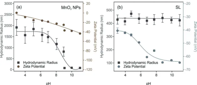
The pH-dependence of size and zeta potential of MnO2NPs is shown in Fig. 2a. In acidic and neutral pH, the MnO2 NPs undergo excessive and rapid aggregation and the hydrodynamic radii of aggregates exceeded 1.5mm. Thus, these conditions are not suitable to obtain monodisperse particle dispersions for further experiments. As the pH becomes basic, the particle size decreased significantly, reaching a radius of (832) nm with a PDI of 11.9% at pH 9 and remained the same within the experimental error until pH 11.
These aggregation trends can be explained by observing the accompanying changes in zeta potentials.55 Accordingly, the particles have low absolute zeta potential less than 20 mV up to pH 7, where the electrostatic forces are overcome by the van der Waals forces.56 In basic medium, surface hydroxides are deprotonated, and at pH 9, MnO2NPs acquire a high negative zeta potential of (37 1) mV, which is high enough for electrostatic repulsion forces to dominate. In Fig. 2b, the SL zeta potential and size dependence on the pH is shown.
Throughout the pH range of 3–11, the SL particles maintained an average hydrodynamic radius of (43216) nm, indicating high colloidal stability. The magnitude of the zeta potential increases gradually as the pH is increased owning to the increased deprotonation of the sulfate groups on the surface of SL. At pH 9, SL particles have a zeta potential of (651) mV and a hydrodynamic radius of (441 33) nm with a PDI of 20.9%. The dispersion characteristics of the MnO2NPs and SL particles at pH 9 are summarized in Table S2 (ESI†).
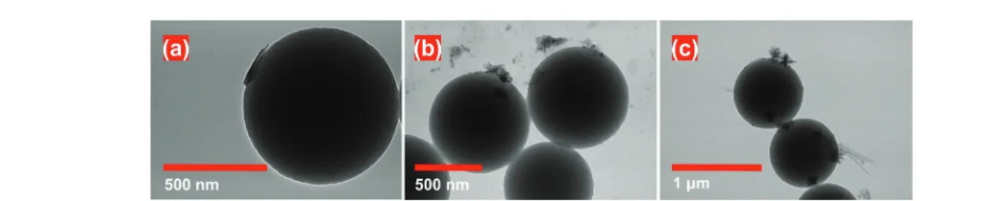
The morphology of SL particles as well as MnO2 NPs was visualizedviaelectron microscopy. The SEM and TEM images of SL particles, shown in Fig. S2a and b (ESI†), respectively, feature the well-defined spherical morphology as well as the relatively low polydispersity of the prepared SL particles.
On the other hand, MnO2NPs show flaky morphology as shown in the SEM image in Fig. S2c (ESI†). The aggregated state of the sample is attributed to drying process during SEM sample preparation. The TEM images of MnO2NPs, shown in Fig. S2d–f (ESI†), further feature the flaky nature of the MnO2
NPs. Note that the hydrodynamic sizes measured by DLS are slightly higher than those of the individual particles observed in the SEM and TEM images due to the polydispersity of the particles and the presence of trace aggregates in the samples, whose effect is more pronounced in the light scattering measurements.
Homoaggregation of SL and MnO2NPs
The aggregation tendency of SL at different SL concentrations and 1.0 M ionic strength was carried out to optimize the experimental conditions for later aggregation rate measurements.
By setting the background salt concentration at 1.0 M, all electrostatic repulsive forces are screened and thus, SL are expected to undergo rapid aggregation according to the Derjaguin, Landau, Verwey and Overbeek (DLVO) theory.57,58 As shown in Fig. 3a, the slopes of the linear fits of Fig. 1 XPS survey spectrum of the obtained MnO2NPs. The O KLL and Fe
LMM represent Auger transitions involving energy levels K, L and M.
hydrodynamic radius versus time data increase when the concentration of SL was raised.
The apparent aggregation rate constants (kapp) as well as the aggregation half-time (T1/2) for the corresponding samples were calculated using eqn (2) and (3), respectively, which are plotted in Fig. 3b as a function of the SL concentration. The data clearly show that kapp increases and T1/2 decreases with increasing particle concentration as a result of accelerated aggregation in concentrated samples. Moreover, in measurements such as those in Fig. 3a, the linear trends in the hydrodynamic radius–time data refer to early stage of aggregation and indicate the absence of higher ranked aggregates, which would cause deviation from linearity.46 Accordingly, a compromised SL concentration of 125 ppm was used in further measurements, where early stage of aggregation can be followed, while the
scattering intensity is high enough for reliable DLS measurements.
The salt-induced aggregation of both particles was also assessed at different ionic strengths. Eqn (1) was used to obtain the stability ratio values at the corresponding NaCl concentra- tions. As shown in Fig. 4, the stability ratio of SL significantly decreased as the ionic strength was increased until it reached unity at the critical coagulation concentration (CCC) of 250 mM, the concentration that separates slow and fast aggregation regimes. The DLVO theory states that the salt constituent ions screen the surface charge resulting in shrinking of the electric double layer and weakening of the repulsive electrostatic forces around SL particles. Thus, when salt concentrations equal or exceed the CCC, the van der Waals attractive forces dominate, and particles undergo diffusion-controlled aggregation.
Fig. 2 The pH dependence of the hydrodynamic radius (squares) and zeta potential (circles) of (a) MnO2NPs and (b) SL particles. The concentration of the MnO2NPs and SL particles was 50 and 125 ppm, respectively, in the dispersions. The ionic strength was set to 1 mM. The lines are just to guide the eyes.
Fig. 3 (a) Time-resolved DLS measurements of SL at different concentrations at 1.0 M ionic strength. The straight lines represent the linear fits used to calculate the apparent aggregation rate constants with eqn (2). (b) The apparent aggregation rate constant (kapp) as well as the aggregation half-time (T1/2) at different particle concentrations, obtainedviaeqn (2) and (3), respectively.
Similar findings are reached when the accompanying changes in SL zeta potentials at different ionic strengths are measured. SL possesses high zeta potential at low salt levels due to the presence of the deprotonated sulfate groups. As more salt is introduced, the zeta potential around SL drops owing to surface charge screening. The Poisson–Boltzmann theory59was used to fit the zeta potential data and a charge density of15.0 mC m2 was determined at the slip plane (Table S2, ESI†).
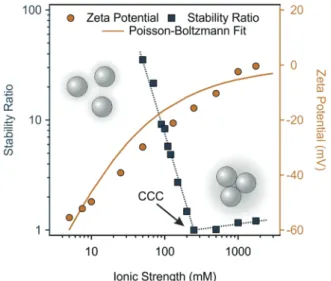
Similar tendencies can be seen for MnO2 NPs in Fig. 5.
The increase in the ionic strength gradually decreased the stability ratio as well as the magnitude of zeta potential because of charge screening, and the subsequent predominance of van
der Waals forces. The CCC occurred at 10 mM, which indicates rather low colloidal stability of the bare MnO2NPs. Upon fitting the zeta potential data with the Poisson–Boltzmann model, the resulting surface charge density of MnO2NPs was5.2 mC m2. In Fig. 5, the Poisson–Boltzmann fit somewhat deviates from the MnO2NPs zeta potential data points at low salt concentrations, which is attributed to the electrokinetic effect reported earlier.60 The surface charge density of the MnO2NPs is significantly lower than the one determined for SL, which led to a higher CCC for SL in line with the prediction of the DLVO theory, since the resistance against salt-induced aggregation is stronger for particles of higher charge and thus, of stronger electrical double layer forces. Besides, the aggregation mechanism follows the prediction of the DLVO theory in both cases, similar to other charged colloidal particles dispersed in salt solutions.46,55,61–66
PDADMAC functionalization of MnO2NPs
Since the aim was to attach MnO2NPs to the SL surfaces, the charge balance must be changed to achieve opposite charges on the interacting particles. Accordingly, MnO2 NPs were functionalized with PDADMAC polyelectrolyte. It is well known that polyelectrolytes adsorb strongly on oppositely charged surfaces and other molecules,67,68 therefore, it was expected that the original negative sign of MnO2NPs turns to positive after adding the appropriate amount of PDADMAC. Therefore, the precise dose was determined and fine-tuned so that the functionalized particles form stable dispersions. The zeta potential values of MnO2 NPs determined at different PDADMAC doses are shown in Fig. 6.
At low PDADMAC doses, the overall particle charge was negative, as indicated by the zeta potential values, which gradually increased as more PDADMAC was introduced.
Around 20 mg PDADMAC/g MnO2 NPs, the zeta potential approached zero. At the isoelectric point (IEP), the amount of Fig. 4 Stability ratio (squares) and zeta potential (circles) values of SL
particles as a function of the ionic strength. The pH was kept at 9 and the SL concentration was 125 ppm in all samples. The dotted blue line only serves as eye guidance. The continuous gold line is the Poisson–Boltz- mann fit.
Fig. 5 Stability ratio (squares) and zeta potential (circles) values of 100 ppm MnO2NPs dispersions as a function of the ionic strength. The pH was kept at 9 in all samples. The dotted blue line only serves as eye guidance. The continuous grey line is the Poisson–Boltzmann fit.
Fig. 6 Stability ratio (squares) and zeta potential (circles) values of MnO2 NPs at different PDADMAC doses. The ionic strength was 1 mM and the pH was 9. The concentration of MnO2NPs was kept at 100 ppm. The solid lines serve as eye guidance. The polyelectrolyte concentration is expressed in mg PDADMAC per one gram of MnO2NPs.
positive and negative charges are balanced and thus, the particles have zero net charge. Higher doses of PDADMAC resulted in charge reversal leading to positively charged particles.
Similar charge reversal was reported earlier for oppositely charged particle–polyelectrolyte systems.64,66,69The zeta potential reached a maximum value at the onset of the adsorption saturation plateau (ASP) at 100 mg g1dose, where the MnO2NPs surface became saturated with adsorbed PDADMAC and further added polyelectrolytes remain dissolved in the solution.70
Moreover, the stability ratios were measured under the same experimental conditions to assess the colloidal stability of the PDADMAC-functionalized MnO2NPs dispersions. Fig. 6 shows that the gradual decrease in zeta potential values is paralleled with changes in the stability ratios. When the particles have high zeta potential (either positive or negative), the stability ratio values are large indicating stable dispersions. However, at PDADMAC doses around the IEP, the stability ratios drop to a value of one, which indicates rapid particle aggregation and unstable dispersions. Such a behavior is typical for oppositely charged particle–polyelectrolyte systems63,66,67and qualitatively agrees with the prediction of the DLVO theory.57,58
Lastly, since the MnO2 NPs surface became saturated with PDADMAC at doses that occur at or beyond the onset of the zeta
potential plateau, the particles prepared at 200 mg g1dose are denoted as PMn. At this experimental condition, the forming PMn possess high positive charge and high stability ratio and they are suitable for heteroaggregation with oppositely charged SL.
Heteroaggregation of PMn with SL
Based on the above results, oppositely charged PMn and SL particles were mixed in different ratios, while the concentration of negatively charged SL was kept at 125 ppm. In the resulting SPMn composite, the intensity of the scattered light originates mostly from SL particles rather than MnO2NPs, as the magnitude of the intensity is proportional to the sixth power of the size of the scattering object,71 which is also evident from the scattering intensity data of individual particles in Table S2 (ESI†). The zeta potential values at different PMn doses are shown in Fig. 7. At low doses, the overall charge of the particles is negative and slowly increased as more PMn were introduced into the system indicating their adsorption on the SL particles. The IEP occurred around a dose of 10 mg g1, where the zeta potential approaches zero. Higher doses of PMn led to positively charged particles.
Such a charge inversion is common in polyelectrolyte–particle systems as discussed before, nevertheless, it was rarely reported in dispersions containing oppositely charged particles.72,73At and beyond 30 mg g1, the zeta potential reached a maximum value, where SL surface most likely became saturated with adsorbed PMn at dose values corresponding to the onset of the ASP.
Stability ratios were determined under the same experimental conditions. As Fig. 7 shows, large magnitude of zeta potential in both in the negative and positive regimes corresponds to large stability ratio values indicating stable dispersions. However, at PMn doses around the IEP, the stability ratios approach unity indicating unstable dispersions. Several studies on latex particles have attributed the predominant interparticle forces to DLVO- type interaction,65,67,74 as discussed in the previous section.
Thus, it is certain that the functionalization with PMn particles did not lead to the appearance of major additional interaction forces, and the aggregation mechanism is driven by the balance between DLVO type forces, namely, electrostatic double layer repulsion and van der Waals attraction. The latter one gradually predominates, when the overall charge of the particles approaches zero, i.e., around the IEP, while the particles are stabilized by electrostatic repulsion at doses below or above this point. SPMn refers to a composite of 100 mg PMn per one gram of SL forming highly stable colloid.
Fig. 7 Stability ratio (squares) and zeta potential (circles) values of SL particles in the presence of PMn at different concentrations. The concen- tration of SL was kept at 125 ppm, whereas the ionic strength was 1 mM and the pH was 9. The mg g1unit refers to mg PMn per one gram of SL.
The solid lines serve as eye guidance only.
Fig. 8 TEM images of SPMn system at PMn doses of (a) 0.1 mg g1, (b) 10 mg g1, and (c) 100 mg g1.
The immobilization of PMn on SL was visualized by TEM images (Fig. 8), which were taken at PMn doses of 0.1, 10, and 100 mg g1, corresponding to concentrations below, around, and above that at the IEP. The TEM sample preparation involves solvent removal, which typically leads to mild aggregation of the particles. However, the images clearly proved
the immobilization and increasing number of PMn can be observed on SL as the dose was increased in the samples.
In addition, the immobilization of PMn on SL was also visualizedviaAFM imaging. In these measurements, the SPMn sample was subjected to minimal changes due to simpler sample preparation, e.g., neither vacuum drying, nor metal coating is required. Fig. 9 shows the AFM images of SPMn (100 mg PMn/g SL, as indicated above) along with the height profiles.
The functionalized MnO2 NPs are clearly immobilized on the SL particles, forming antioxidant colloidal molecules. The height profile analysis also confirms the successful formation of the SPMn and indicates significantly different sizes for the component SL and PMn particles in accordance with the SEM and TEM images (Fig. S2, ESI†).
Antioxidant activity
The CAT-like activity of the MnO2NPs and SPMn particles was assessedviaa standard assay,49in which H2O2breaks down in Fig. 9 (a) AFM amplitude images of SPMn deposited on a mica substrate as well as (b) the height profiles taken along the indicated white line.
Fig. 10 CAT-like activity of MnO2NPs and SPMn at 25, 50, and 751C for both materials. The particle concentrations were 10 ppm and 100 ppm (in SL) for MnO2NPs and SPMn, respectively. The solid lines are the Michae- lis–Menten fits described by eqn (4).
Table 1 Comparison of the results of CAT and SOD activity assays obtained for the MnO2NPs and SPMn particles
Material Kma(mM) vmaxa(105M s1) IC50b(ppm) MnO2NPs (251C) 0.0830.011 3.0790.101 0.2740.012 MnO2NPs (501C) 0.0820.008 1.5170.036 0.1320.005 MnO2NPs (751C) 0.0740.010 1.6090.049 0.1920.010 SPMn (251C) 0.0990.010 3.3230.079 0.3110.013 SPMn (501C) 0.1180.017 2.3140.085 0.2710.012 SPMn (751C) 0.1060.025 2.3770.139 0.4170.017
aCalculated by eqn (4).bDetermined in SOD activity assays.
the presence of the enzyme or its mimic. The reaction rates versus concentration data points determined at different temperatures are plotted in Fig. 10.
One can notice that the experimental points can be well fitted with the Michaelis–Menten model (eqn (4))50and theKm
and vmax values were determined from the fits in all cases (Table 1). The vmax is the maximum reaction rate observed, where higher H2O2concentrations do not increase the rate any further, which can be attributed to the saturation of the catalytic sites. The Km is the H2O2 concentration that correspond to the rate half that of thevmax. TheKmvalue is a measure of the affinity between the catalyst and the substrate, where a lowerKmvalue indicates a higher affinity between the enzyme-like material and the substrate.
The results obtained revealed that the immobilization had no effect on the activity of MnO2NPs, as evident by the closeKm andvmaxvalues of SPMn and MnO2NPs determined at 251C.
In other words, neither the PDADMAC functionalization nor the attachment to SL altered the H2O2decomposition ability of MnO2NPs. Moreover, the CAT activity of both MnO2NPs and SPMn was obtained after the corresponding stock dispersions were thermally treated by immersion in a water bath at 501C and 75 1C for 90 min, and subsequent cooling to room temperature. As shown in Fig. 10, thermal treatment resulted in a decrease in the CAT activity of both MnO2NPs and SPMn compared to the untreated counterparts. The data indicate that the reduction of CAT activity was the same regardless of the temperature imposed, but the loss is more emphasized for MnO2 NPs than for SPMn. However, no unambiguous explanation can be given for the reason of such decrease based on the present experimental data. Comparatively, the native CAT completely loses its activity at 701C after 30 min heating.75 Although the thermal treatment also affected the activity of SPMn particles, they can still be considered as very active catalysts in H2O2decomposition, which shows that SPMn had
remarkable thermal and structural stability, making it a versatile candidate as antioxidant material in industrial processes for instance, where higher temperature is applied. The ability of the MnO2NPs and SPMn to dismutase superoxide radical ions was tested by the Fridovich assay.51The inhibition of the NBT-radical reaction was calculated using eqn (5) and plotted as a function of the MnO2NPs or SPMn concentration in Fig. 11.
The IC50values for MnO2NPs and SPMn were very similar at 25 1C (Table 1), but higher than the IC50 for native SOD (0.07 ppm).63Thus, the functional integrity of MnO2NPs was kept upon polyelectrolyte functionalization and immobilization on SL. It is evident from the data of the heated samples that, unlike the CAT activity, there is no loss in SOD activity of either bare or immobilized MnO2 NPs, even though the composite were thermally treated in a water bath at 501C and 751C for 90 min. The native SOD enzyme, however, was reported to lose its activity after 20 min at elevated temperatures.62 These results clearly indicate that the MnO2NPs possess remarkable antioxidant potential, with preserved activity and excellent colloidal stability upon immobilization.
Conclusions
MnO2NPs with antioxidant activity were synthesized, function- alized with PDADMAC, and immobilized on SL particles.
Heteroaggregation was rationalized as an adsorption process of the PMn particles on the SL surface due to their opposite charges. The positively charged PMn particles adsorbed strongly on the SL leading to charge neutralization and charge reversal at the appropriate PMn doses. The colloidal stability of the samples was assessed, and the findings confirmed that the aggregation in the PMn–SL systems is driven by DLVO-type forces. Accordingly, the electrostatic double layer repulsion stabilizes the dispersions at low and high PMn doses, where Fig. 11 Inhibition of the NBT-superoxide radical ion reaction by (a) MnO2NPs as well as (b) SPMn determined at 251C (squares), 501C (circles), and 751C (hexagons). The inhibition values were calculated using eqn (5). The solid lines are mathematical functions to interpolate the IC50values.
the particles possess significant charge. Near the IEP, however, the dispersions were unstable and diffusion-controlled aggre- gation occurred due to the lack of charges,i.e., to the disap- pearance of the electrostatic double layers and predominance of attractive van der Waals forces. The SPMn hybrid showed excellent colloidal and functional stabilities. The CAT-like activity of MnO2 NPs was maintained, although decreased, upon immobilization on SL and upon heating up to 751C, as indicated by the similarity of Michaelis–Menten parameters for both particles. The results of the SOD-like activity measure- ments implied no loss in MnO2NPs activity upon immobiliza- tion or heating, as similar IC50values were determined. These facts indicate that the obtained SPMn composites can be effectively used to combat reactive oxygen species in hetero- geneous systems due to the excellent colloidal stability of the SPMn hybrid.
Conflicts of interest
There are no conflicts to declare.
Acknowledgements
Financial support from the Ministry of Human Capacities (20391-3/2018/FEKUSTRAT) and the Eo¨tvo¨s Lo´ra´nd Research Network (96130) is gratefully acknowledged. V. H. is supported by the Premium Postdoctoral Research Program (PPD-461042).
The support from the University of Szeged Open Access Fund (5359) is gratefully acknowledged.
References
1 X. Ma, A. C. Hortelao, T. Patino and S. Sanchez,ACS Nano, 2016,10, 9111–9122.
2 Y. H. Lin, J. S. Ren and X. G. Qu,Acc. Chem. Res., 2014,47, 1097–1105.
3 K. Kirkorian, A. Ellis and L. J. Twyman, Chem. Soc. Rev., 2012,41, 6138–6159.
4 H. Wei and E. K. Wang, Chem. Soc. Rev., 2013, 42, 6060–6093.
5 J. S. Mu, L. Zhang, G. Y. Zhao and Y. Wang, Phys. Chem.
Chem. Phys., 2014,16, 15709–15716.
6 J. J. X. Wu, X. Y. Wang, Q. Wang, Z. P. Lou, S. R. Li, Y. Y. Zhu, L. Qin and H. Wei,Chem. Soc. Rev., 2019,48, 1004–1076.
7 S. I. Tsekhmistrenko, V. S. Bityutskyy, O. S. Tsekhmistrenko, V. M. Polishchuk, S. A. Polishchuk, N. V. Ponomarenko, Y. O. Melnychenko and M. Y. Spivak,Regul. Mech. Biosyst., 2018,9, 469–476.
8 S. Murath, N. B. Alsharif, S. Saringer, B. Katana, Z. Somosi and I. Szilagyi,Crystals, 2020,10, 148.
9 B. Bhushan and P. Gopinath, J. Mater. Chem. B, 2015, 3, 4843–4852.
10 D. Wang, X. L. Song, P. Li, X. J. J. Gao and X. F. Gao,J. Mater.
Chem. B, 2020,8, 9028–9034.
11 X. J. Wu, T. M. Chen, J. X. Wang and G. W. Yang,J. Mater.
Chem. B, 2018,6, 105–111.
12 H. Tokuyama, S. Yamago, E. Nakamura, T. Shiraki and Y. Sugiura,J. Am. Chem. Soc., 1993,115, 7918–7919.
13 L. L. Dugan, J. K. Gabrielsen, S. P. Yu, T. S. Lin and D. W. Choi,Neurobiol. Dis., 1996,3, 129–135.
14 H. Jiang, Z. H. Chen, H. Y. Cao and Y. M. Huang,Analyst, 2012,137, 5560–5564.
15 W. W. He, Y. T. Zhou, W. G. Warner, X. N. Hu, X. C. Wu, Z. Zheng, M. D. Boudreau and J. J. Yin,Biomaterials, 2013, 34, 765–773.
16 M. Moglianetti, E. De Luca, P. A. Deborah, R. Marotta, T. Catelani, B. Sartori, H. Amenitsch, S. F. Retta and P. P. Pompa,Nanoscale, 2016,8, 3739–3752.
17 L. Rastogi, D. Karunasagar, R. B. Sashidhar and A. Giri, Sens. Actuators, B, 2017,240, 1182–1188.
18 J. S. Mu, L. Zhang, M. Zhao and Y. Wang,ACS Appl. Mater.
Interfaces, 2014,6, 7090–7098.
19 C. Murugan, N. Murugan, A. K. Sundramoorthy and A. Sundaramurthy,Chem. Commun., 2019,55, 8017–8020.
20 W. Chen, J. Chen, A. L. Liu, L. M. Wang, G. W. Li and X. H. Lin,ChemCatChem, 2011,3, 1151–1154.
21 S. Ghosh, P. Roy, N. Karmodak, E. D. Jemmis and G. Mugesh,Angew. Chem., Int. Ed., 2018,57, 4510–4515.
22 Z. H. Dai, S. H. Liu, J. C. Bao and H. X. Jui,Chem. – Eur. J., 2009,15, 4321–4326.
23 T. M. Chen, H. Zou, X. J. Wu, C. C. Liu, B. Situ, L. Zheng and G. W. Yang,ACS Appl. Mater. Interfaces, 2018,10, 12453–12462.
24 T. R. Lin, L. S. Zhong, Z. P. Song, L. Q. Guo, H. Y. Wu, Q. Q. Guo, Y. Chen, F. F. Fu and G. N. Chen, Biosens.
Bioelectron., 2014,62, 302–307.
25 L. F. Wang, Y. Li, L. Zhao, Z. J. Qi, J. Y. Gou, S. Zhang and J. Z. Zhang,Nanoscale, 2020,12, 19516–19535.
26 S. W. Wu, M. Qiu, B. C. Guo, L. Q. Zhang and Y. Lvov,ACS Sustainable Chem. Eng., 2017,5, 1775–1783.
27 W. Li, Z. Liu, C. Q. Liu, Y. J. Guan, J. S. Ren and X. G. Qu, Angew. Chem., Int. Ed., 2017,56, 13661–13665.
28 N. Singh, M. A. Savanur, S. Srivastava, P. D’Silva and G. Mugesh,Angew. Chem., Int. Ed., 2017,56, 14267–14271.
29 W. Chen, Y. Y. Yan, R. L. Han, J. Hu, Y. F. Hou and K. Q. Tang,Photochem. Photobiol. Sci., 2021,20, 153–160.
30 L. T. Yang, S. T. D. Chueng, Y. Li, M. Patel, C. Rathnam, G. Dey, L. Wang, L. Cai and K. B. Lee,Nat. Commun., 2018, 9, 3147.
31 G. Dey, L. T. Yang, K. B. Lee and L. Wang,J. Phys. Chem. C, 2018,122, 29017–29027.
32 M. Sawangphruk, P. Srimuk, P. Chiochan, A. Krittayavathananon, S. Luanwuthi and J. Limtrakul,Car- bon, 2013,60, 109–116.
33 K. G. Lee, J. M. Jeong, S. J. Lee, B. Yeom, M. K. Lee and B. G. Choi,Ultrason. Sonochem., 2015,22, 422–428.
34 D. R. Hu, L. J. Chen, Y. Qu, J. R. Peng, B. Y. Chu, K. Shi, Y. Hao, L. Zhong, M. Y. Wang and Z. Y. Qian,Theranostics, 2018,8, 1558–1574.
35 S. J. Yao, S. Yuan, J. H. Xu, Y. Wang, J. L. Luo and S. S. Hu, Appl. Clay Sci., 2006,33, 35–42.
36 D. Gu, J. C. Tseng, C. Weidenthaler, H. J. Bongard, B. Spliethoff, W. Schmidt, F. Soulimani, B. M.
Weckhuysen and F. Schuth,J. Am. Chem. Soc., 2016,138, 9572–9580.
37 T. Takashima, K. Hashimoto and R. Nakamura,J. Am. Chem.
Soc., 2012,134, 1519–1527.
38 M. Cheng, Y. Yu, W. D. Huang, M. Fang, Y. Chen, C. M. Wang, W. L. Cai, S. Y. Zhang, W. X. Wang and W. J. Yan,ACS Biomater. Sci. Eng., 2020,6, 4985–4992.
39 T. Sasaki,J. Ceram. Soc. Jpn., 2007,115, 9–16.
40 T. C. Cao, M. Borkovec and G. Trefalt, Colloids Interfaces, 2020,4, 52.
41 X. N. Wang, S. Wang, X. L. Pan and G. M. Gadd,Chemo- sphere, 2019,221, 486–492.
42 O. Ben Moussa, L. Tinat, X. J. Jin, W. Baaziz, O. Durupthy, C. Sayag and J. Blanchard,ACS Catal., 2018,8, 6071–6078.
43 J. M. Lopez-Lopez, A. Schmitt, A. Moncho-Jorda and R. Hidalgo-Alvarez, Adv. Colloid Interface Sci., 2009, 147, 186–204.
44 X. Du and J. H. He,J. Appl. Polym. Sci., 2008,108, 1755–1760.
45 A. V. Delgado, E. Gonzalez-Caballero, R. J. Hunter, L. K. Koopal and J. Lyklema,Pure Appl. Chem., 2005, 77, 1753–1805.
46 H. Holthoff, S. U. Egelhaaf, M. Borkovec, P. Schurtenberger and H. Sticher,Langmuir, 1996,12, 5541–5549.
47 G. Trefalt, I. Szilagyi, T. Oncsik, A. Sadeghpour and M. Borkovec,Chimia, 2013,67, 772–776.
48 M. Elimelech, J. Gregory, X. Jia and R. A. Williams,Particle deposition and aggregation: measurement, modeling, and simulation, Butterworth-Heinemann Ltd, Oxford, 1995.
49 A. C. Maehly and B. Chance,Methods Biochem. Anal., 1954, 1, 357–424.
50 K. A. Johnson and R. S. Goody, Biochemistry, 2011, 50, 8264–8269.
51 C. Beaucham and I. Fridovich, Anal. Biochem., 1971, 44, 276–287.
52 M. C. Biesinger, B. P. Payne, A. P. Grosvenor, L. W. M. Lau, A. R. Gerson and R. S. Smart, Appl. Surf. Sci., 2011, 257, 2717–2730.
53 E. S. Ilton, J. E. Post, P. J. Heaney, F. T. Ling and S. N. Kerisit, Appl. Surf. Sci., 2016,366, 475–485.
54 J. Y. Li, X. L. Wu, X. H. Zhang, H. Y. Lu, G. Wang, J. Z. Guo, F. Wan and R. S. Wang, Chem. Commun., 2015, 51, 14848–14851.
55 M. Galli, S. Saringer, I. Szilagyi and G. Trefalt, Colloids Interfaces, 2020,4, 20.
56 J. Israelachvili,Intermolecular and surface forces, Academic Press, London, 3rd edn, 2011.
57 E. J. W. Verwey and J. T. G. Overbeek,Theory of stability of lyophobic colloids, Elsevier, Amsterdam, 1948.
58 B. Derjaguin and L. D. Landau, Acta Physicochim. URSS, 1941,14, 633–662.
59 D. F. Evans and H. Wennerstrom,The colloidal domain, John Wiley, New York, 1999.
60 M. Borkovec, S. H. Behrens and M. Semmler, Langmuir, 2000,16, 5209–5212.
61 J. Hierrezuelo, A. Sadeghpour, I. Szilagyi, A. Vaccaro and M. Borkovec,Langmuir, 2010,26, 15109–15111.
62 M. Pavlovic, M. Nafradi, P. Rouster, S. Murath and I. Szilagyi,J. Colloid Interface Sci., 2019,543, 174–182.
63 M. Pavlovic, P. Rouster and I. Szilagyi,Nanoscale, 2017, 9, 369–379.
64 P. Rouster, M. Pavlovic, S. Saringer and I. Szilagyi,J. Phys.
Chem. C, 2018,122, 11455–11463.
65 S. Saringer, R. A. Akula, A. Szerlauth and I. Szilagyi,J. Phys.
Chem. B, 2019,123, 9984–9991.
66 S. Saringer, P. Rouster and I. Szilagyi, Langmuir, 2019,35, 4986–4994.
67 I. Szilagyi, G. Trefalt, A. Tiraferri, P. Maroni and M. Borkovec,Soft Matter, 2014,10, 2479–2502.
68 K. Kolman, O. Nechyporchuk, M. Persson, K. Holmberg and R. Bordes,Colloids Surf., A, 2017,532, 420–427.
69 L. Avadiar and Y. K. Leong,Colloid Polym. Sci., 2011,289, 237–245.
70 E. Seyrek, J. Hierrezuelo, A. Sadeghpour, I. Szilagyi and M. Borkovec,Phys. Chem. Chem. Phys., 2011,13, 12716–12719.
71 M. I. Mishchenko, L. D. Travis and A. A. Lacis,Scattering, absorption, and emission of light by small particles, University Press, Cambridge, 2002.
72 N. B. Alsharif, G. F. Samu, S. Sa´ringer, S. Mura´th and I. Szilagyi,J. Mol. Liq., 2020,309, 113066.
73 M. Pavlovic, P. Rouster, E. Bourgeat-Lami, V. Prevot and I. Szilagyi,Soft Matter, 2017,13, 842–851.
74 F. J. M. Ruiz-Cabello, G. Trefalt, T. Oncsik, I. Szilagyi, P. Maroni and M. Borkovec, J. Phys. Chem. B, 2015, 119, 8184–8193.
75 A. Dincer and T. Aydemir, J. Enzyme Inhib., 2001, 16, 165–175.