Robust Fractional Order Controllers for Distributed Systems
Eva-H. Dulf, Daniel Timis, Cristina-I. Muresan
Department of Automation, Technical University of Cluj-Napoca, Memorandumului 28, 400114, Cluj-Napoca, Romania, e-mail:
eva.dulf@aut.utcluj.ro; daniel.timis@student.utcluj.ro; cristina.pop@aut.utcluj.ro
Abstract: An important step in any control system design is to account for the fault tolerance desired for the system at an early stage of development. It is not enough to test the fault tolerance after the implementation, as the tuning possibilities may be insufficient to ensure tolerance for an unexpected fault, it is better to monitor at the design phase. The control research community is interested in fault tolerant control system design, but only specific applications are addressed. The present paper deals with such a fault tolerant control system for a complex chemical process, the (13C) isotope separation columns cascade. To ensure the robustness to uncertainties of the designed system, the controller is a fractional order type, tuned using the particle swarm optimization method. The simulation results were obtained using the TrueTime Matlab toolbox.
Keywords: fault tolerant systems; distributed control system; fractional order controllers;
robust control system
1 Introduction
Currently, the automatic control field is going through a continuous state of development. Research gives us new solutions and new control concepts. One of these is represented by cyber-physical systems, an interconnection between computers and physical systems. This modern type of system is embedding the computer into feedback loops, to monitor and control physical processes in various domains like: military and aeronautical systems, wastewater treatment, medical devices, manufacturing, automotive systems and so on. This approach gives us the chance to use preferred and efficient controller algorithms as opposed to old analog controllers, but the complexity of this approach increases. Because of this high level of complexity, we have to focus our attention towards the fault tolerance of the control system [1, 2]. To prevent critical failures we have to keep the local faults below a certain level. This represents an important objective to be pursued by researchers, who try to address it in the most efficient way.
Nowadays, fractional calculus is one of the most important and complex methods to be used in order to describe a complete behavior for a wide range of mathematical models from domains like: electrical and mechanical engineering, aeronautical engineering, computational mathematics, etc. A classic PID controller introduces three degrees of freedom, whereas a fractional PID controller has five degrees of freedom due to the fractional powers of the integrative and derivative effects. [3, 4]. The main disadvantage of the fractional controller design is caused by the complexity of the algorithm. By using classical tuning methods, it is hard to determine the fractional PID parameters needed to meet the given specifications. A solution for this disadvantage could be bio-inspired optimization algorithms [5].
This paper presents a simulation of a fault tolerant cyber-physical system, applied on a plant consisting of three (13C) isotope separation columns, connected in a cascade structure. The used controllers are of fractional order, designed using the particle swarm optimization algorithm and implemented using a new continuous- to-discrete-time operator.
2 Control Structure
2.1 Robust Fractional Order Controller Design
A fractional order PID controller may be easily described in the Laplace domain as follows:
K s
s 1 K K s
C d
i P
F , (1)
where Kp, Ki, Kd are the proportional, integral and derivative gains, while and represent the fractional orders of integration and differentiation. The design of the fractional order PID controller in (1) follows the classical tuning rules for such type of controllers and it is carried out in the frequency domain [6, 7, 8]. To tune the parameters of the fractional order controller, three performance specifications are imposed to shape the closed loop response. These performance specifications refer to a gain crossover frequency and a phase margin, linked to a specific settling time and overshoot for the closed loop system, as well as the iso-damping property that allows for an increased robustness to open loop gain variations.
In mathematical terms, the three performance specifications may be easily described through the modulus and phase equations, while the iso-damping property is expressed using the derivative condition in the following equations:
CF( jwgc)×GP
( )
jwgc =0dB (2)arg C
(
F( jwgc)×GP( )
jwgc)
= -p+jm (3)
d 0 j G j C arg d
cg
P
F
(4)
where GP stands for the transfer function of the process to be controlled, assumed here to be of the following form:
GP
( )
jw =A jw( )
1 =Re P( )
w +1jIm P( )
w (5) Considering the following result:
,r
2 sin r 2 j cos r jr
(6) and denoting the modulus, phase and derivative conditions as function f1, f2 and f3, respectively, the three performance specifications in (2)-(4) can be further expanded as indicated here:
f1=KP 1+Kiwgc -la+Kdwgc
mb+2wm-lKiKdcos (l +m)p
2 æ
æç ö
æ÷- - Re P2(wgc)+Im P2(wgc)
(7)
f2= wgc mKdsin pm
2 æ æç ö
æ÷- wgc -lKisin pl
2 æ æç ö
æ÷ 1+wgc
mKdcos pm 2 æ æç ö
æ÷+ wgc
-lKicos pl 2 æ æç ö
æ÷
-tg -p + jm-arctg Im P(wgc) Re P(wgc) æ
æçç ö æ÷÷
æ
æçç ö
æ÷÷
(8)
f3= c
1+wgc
-lKicos pl 2 æ æç ö
æ÷+ wgc
mKdcos pm 2 æ æç ö
æ÷ æ
æç ö
æ÷
2-dæGp( jw) dw w=wgc
(9) where a=2 cospl
2 +Kiwgc
-l and b=2 cospm 2 +Kdwgc
m
c=c1+c2+c3,c1=KiKd
(
m + l)
wgcm-l-1sin p l -m( )
2 æ
æç ö
æ÷, c2=Kdmwgc
m-1sin pm 2 æ æç ö
æ÷ and c3=Kilwgc
-l-1sin pl 2 æ æç ö
æ÷.
Several techniques exist to solve the resulting system of nonlinear equations (2)- (4). In this paper, the proposed technique is based on a modified version of the Particle Swarm Optimization (PSO) algorithm as developed by Eberhart and Kennedy [9, 10]. In the PSO algorithm, the parameters of the controller transfer function in (1) are represented by a particle and each of these particles keeps track of its best solution, the personal best, and of the best value of any particle, the global best. Each particle modifies its position according to its current position, current velocity, the distance between its current position and the personal best and the distance between its current position and the global best. The PSO algorithm is based on finding the best values for all particles such as a fitness function is minimized. In this paper, the fitness function is selected to be the sum of the performance specifications as expressed in equations (7)-(9).
x f
x f
x fCF 1 2 3
(10) where x=é KP Ki Kd l m
ë æ
æ
T
are the controller parameters.
To avoid falling into local optimal value and to ensure a fast convergence speed of optimization, the inertia weight [11] is used:
1 r q 1 1 p
n 1 m
w gbest(i) bestf
(11)
where m, n, p, q, r are parameters selected according to the nonlinear equations, gbest(i) is the ith global best and bestf is the standard deviation of all the ith generation particles.
2.2 Discrete-Time Implementation of the Fractional Order PID Controller
In order to implement a fractional order PID controller, as given by the transfer function in (1), a new continuous-to-discrete-time operator is used:
s=1+ a Ts
1-z-1
1+ az-1 (12) with z-1 the backward shift operator, Ts the sampling period and α(0,1) – a weighting parameter that allows for an increased flexibility in ensuring a better fitting of the magnitude or phase curve of the original fractional order PID controller. The operator introduced in (12) is an interpolation between the Euler (α=0) and the Tustin (α=1) discretization rules [12].
The first step in the digital approximation consists in a continuous-time fitting of the fractional order PID controller, using a higher order rational transfer function.
Because of its wide acceptance, simplicity and efficiency, the Oustaloup
Recursive Approximation [13] method is selected in this paper. The fitted continuous-time approximation of the fractional order PID controller is then given as:
G(s)=Kc
s-zcj
( )
j=1
Õm
s-pci
( )
i=1
Õn
(13)
where Kc is the gain, zcj are the continuous-time zeros, j=1,2,...,m and pic are the continuous-time poles, i=1,2,…,n.
Once this continuous-time approximation of the fractional order PID controller in (11) has been obtained, the next step is to compute the discrete-time poles and zeros, using the inverse operator of (12):
z=1+a+ asTs
1+ a -sTs (14) The corresponding poles and zeros are then each computed according to the following rules:
pid=1+ a+ apicTs
1+ a -picTs (15)
zjd=1+ a+ azj cTs
1+ a -zcjTs (16) Then, the discrete-time equivalent of the fractional order PID controller has the following form:
G(z)=Kd
z-zdj
( )
j=1
Õn
z-pid
( )
i=1
Õn (17)
where the discrete-time gain Kd is computed based on the equivalency of the continuous-time and discrete-time transfer functions from (13) and (17) in steady state (s=0 and z=1):
Kd=Kc -zj
( )
c j=1Õm Õi=1n
(
1-pid)
-pi
( )
c i=1Õn Õj=1n
(
1-zdj)
. (16) Further details on the new operator (12) and on the effect of can be found in [12] and in [14].2.3 Fault Tolerant Distributed Control System
The modern control systems must be robust and adaptable for the system changes to be functioning, safe and fault tolerant, aspect which leads to the development of multi-agent systems. These systems have a number of independent agents, which possess capabilities such as: communication, computation, sensing and actuation.
In the framework discussed in the present work, an agent is defined as an independent unit having specific functions. A Sensor agent is equipped with one or multiple redundant sensors of the same type to ensure fault-tolerance. The Actuator-agent is equipped with several redundant actuators that can provide the same functions. A Control-agent is capable of performing their own and their nearest neighbor control laws, being able to take over the functions of his neighbor in case of failure. The agents are distributed in the field, in order to complete the control system`s main task. In the case of a decentralized approach, any agent is free to manage and schedule its own activities and can exchange information with other controllers in its neighborhood, without any help from a coordinating agent. In the event of one agent`s failure, the resulting effect will not destabilize the process. Moreover, a neighboring agent could take over the task of a defective controller in order to keep the process near to the initial performances.
3 Case Study
The case study considered herein, consists in the distillation of carbon monoxide, in a train of three series columns, with the end purpose of enriching the natural concentration of the (13C) carbon isotope. The enriching process is a difficult task, since there are very small differences in the nuclear characteristics of the two stable isotopes to be separated: the (12C) and the (13C). The actual equipment, as well as a schematic representation, are given in Figures 1 and 2. A great deal of papers have been published previously by the Authors describing the characteristics and operation of a single column or the cascade, the model of such a plant, as well as several control strategies [15-21].
The entire plant uses a common condenser cooled with liquid nitrogen. Three boilers, installed at the bottom of each column, ensure a gaseous upstream, while the liquid downstream is produced by condensing these vapors on the cold walls of the condenser. The system operates at approximately -190oC, in order for both liquid and gaseous phases of (CO) to co-exist [16, 17, 22].
Figure 1
The (13C) isotope separation column cascade
Figure 2
Schematic representation of the (13C) isotopic separation column cascade
Several sensors and actuators, as pictured in Figure 3, are installed for monitoring and control purposes, such as: seven flow transducers, three pressure transducers at the top of the columns, three differential pressure transducers, three thermocouples for boiler temperature measurements, three dedicated liquid carbon monoxide level transducers in the bottom of the columns, three pumps to ensure the flow between the columns, as well as, a dedicated transducer for the liquid nitrogen level in condenser [23].
Figure 3
Sensors and actuators for the (13C) isotopic separation column cascade
The TrueTime toolbox from Matlab [24] has been used to simulate the distributed system. A section of this system, including the communication between two agents, is presented in Figure 4. The whole system is much more complex, as can be seen in Figure 3, including a series of agents. Figure 4 highlights the communication layer in a subsystem: the “Plant” and the corresponding controller using the send message (“ttSendMsg”) and get message (“ttGetMsg”) blocks through TrueTimeNetwork. It is also included a disturbing node to simulate real scenarios of this highly critical system. [25]
Figure 4
Communication between two agents as a section of the distributed control system of the (13C) isotope separation cascade
y u
data snd
ttSendMsg4 data snd
ttSendMsg3 data snd ttSendMsg2
data snd
ttSendMsg1
rcv data
ttGetMsg4 rcv data
ttGetMsg3 rcv data
ttGetMsg2
rcv data
ttGetMsg1
C disturbing node
Snd Rcv Schedule 1
TrueTime Network
Schedule Pulse
Generator2
Pulse Generator1
Pulse Generator
In Out
Plant
LogicalAND Operator
[snd4]
[rcv4]
[rcv3]
[rcv2]
[rcv1]
[snd3]
[snd2]
[snd1]
[rcv4]
[snd4]
[snd3]
[snd2]
[snd1]
[rcv1]
[rcv3]
[rcv2]
In Out
Controller
Band-Limited White Noise
In order to highlight the efficiency of the proposed control strategy, in this simulation stage, a subsystem having a simple first order transfer function
10s 1 s 1GP
is considered. This simplification does not affect the final results regarding fault tolerance. Imposing the gain crossover frequency of 15 [rad/sec], phase margin of 90o, the above described particle swarm optimization method solves the controller design problem, using equations (7), (8) and (9). With a population size of 50 particles and considering the inertia weights: m=0.9; n=1.01;
p=1.1; q=0.051 and r=1.01, the resulted controller’s parameters are: Kp=71.51, Kd=0.012, Ki=16.5, =0.87 and =0.1. The Bode plot presented in Figure 5 proves the fulfillment of the imposed performances.
To highlight the proposed particle swarm optimization method efficiency, in Figure 6 are presented the particle evolutions after 5, 50, 100 and 150 iterations. It can be seen that the cost function value tends to zero after 50 iterations, Figure 6b, although this number depends on the initial conditions, Figure 6a. With 100 or 150 iterations, Figure 6c and Figure 6d, the accuracy can be improved.
-100 -50 0 50
Magnitude (dB)
10-2 100 102 104
-90 -45 0
Phase (deg)
X: 15 Y: -89.62 Bode Diagram
Frequency (rad/s)
Figure 5
Frequency response of the system with the designed fractional order PID controller
0 100 200 300 400 500 600 700 800 900 1000 1100 -0.2
-0.15 -0.1 -0.05 0 0.05 0.1 0.15 0.2 0.25 0.3
Particles position
Cost function
After 5 iterations
0 2 4 6 8 10
x 10-5 -0.5
0 0.5 1 1.5 2 2.5 3
x 10-7
Particles position
Cost function
After 50 interations
a) b)
-1 -0.5 0 0.5 1 1.5 2 x 10-11 0
0.5 1 1.5 2 2.5 3 3.5
x 10-12
Particles position
Cost function
After 100 iterations
data1
0 0.5 1 1.5 2 2.5
x 10-17 0
1 2 3 4 5 6 7 8 9
x 10-18
Particles position
Cost function
After 150 iterations
c) d)
Figure 6
Particle evolution in the optimization method, presented after: a) 5 iterations; b) 50 iterations; c) 100 iterations; d) 150 iterations
The continuous-time approximation of this fractional order PID controller has been obtained using the Oustaloup Recursive Approximation method within a low frequency bound ωl=0.01 rad/s and a high frequency bound ωh=100 rad/s. The order N=3 has been selected for the fitted continuous-time transfer function, yielding a total of 13 continuous-time poles and zeros. The discrete-time approximation has been obtained using the new continuous-to-discrete-time operator described in Section II.B, with α=0.9 and Ts= 0.0314 s. The Bode diagram in Figure 7 shows that a similar frequency response is obtained for the original fractional order PID controller, as well as its discrete-time approximation.
Figure 7
Frequency response of the ideal fractional order PID controller and of its discrete-time approximation
To test the robustness of the designed control structure, step responses were simulated using a +/-50% gain variation of the process transfer function. In Fig. 8, the step response of the simplified model is presented, highlighting no overshoot in all cases and settling time changes from 0.15 sec to 0.45 sec.
Figure 8
Step response of the closed loop system with nominal and +/-50% gain variation of the process
The next step in testing was the fault-tolerance test. Two schemes as the one, presented in Figure 4, have been used, in which each sensor- and actuator agent is equipped with two redundant sensors and actuators. Each control-agent is capable to perform their own and their nearest neighbor control laws, being able to take over the functions of his neighbor in case of failure. In Figure 9, the simulation results with the first controller failure are presented. If no fault tolerant control structure is implemented, the system output decreases from the steady-state value, Figure 9a. If the proposed strategy is implemented, when the controller fails, the neighboring controller detects this failure and takes over the responsibilities of the first one, obtaining the same steady-state value. The controller changes are not reflected in the system output; hence, the same closed loop system performance is obtained, Figure 9b.
0 5 10 15 20 25 30 35 40 45
0 10 20 30 40 50 60 70 80 90 100
time (seconds)
Output [%]
0 5 10 15 20 25 30 35 40 45
0 0.1 0.2 0.3 0.4 0.5 0.6 0.7 0.8 0.9 1
time (seconds)
Output [/%]
a) b)
Figure 9
Output signal of the subsystem in case of controller failure: a) without fault-tolerant structure; b) with fault-tolerant structure
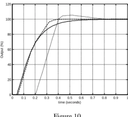
The proposed fault-tolerance being based on the communication between two agents, the network effects on the control structure were tested. While taking into account the communication speed variations and the use of different network types, the step response of the system emphasizes the fact that the system is not affected. The packet loss probability has also been taken into account. Thus,
Figure 10 shows that even in the event of a 50% loss probability, the steady state value of the system remain the same, although the performance changes. In case of a packet loss probability greater than 50%, the second controller must take over the responsibilities of the first one, in order to have comparable performance.
0 0.1 0.2 0.3 0.4 0.5 0.6 0.7 0.8 0.9 1
0 20 40 60 80 100 120
time (seconds)
Output (%)
Figure 10
Step response of the closed loop system with different packet loss probabilities: 0% - solid line, 20% - dash line, 50% - dot line
Conclusions
The present paper uses an agent oriented approach for designing a fault tolerant control system, having the sensors, actuators and controllers communicating through a network. The design of the controllers ensures robustness to gain variations, while the communication between adjacent neighbor agents provides the fault tolerance of the system - in the event of a critical failure, the responsibility of the faulty agent will be passed on to the neighbor. This case study is an insight into the isotope separation columns, connected in a cascade structure, forming a highly critical cyber-physical system. The efficiency of the aforementioned control strategy is proven through simulation results and through the use of dedicated software for multi-agent systems. Future work will be in the area of implementation of this strategy, on a more detailed and complex system.
Acknowledgment
This work was supported by a grant of the Romanian National Authority for Scientific Research and Innovation, CNCS – UEFISCDI, project number PN-II- RU-TE-2014-4-1465, contract number 38/2015.
Cristina Muresan was supported by a grant of the Romanian National Authority for Scientific Research and Innovation, CNCS – UEFISCDI, project number PN- II-RU-TE-2014-4-0598, TE 86/2015.
References
[1] Xiaofeng Wang, Naira Hovakimyan, Lui Sha, “L1Simplex: Fault-Tolerant Control of Cyber-Physical Systems”, 2013 ACM/IEEE International Conference on Cyber-Physical Systems (ICCPS) pp. 41-50
[2] C. M. Krishna, I. Koren, “Adaptive Fault-Tolerance for Cyber-Physical Systems”, 2013 International Conference on Computing, Networking and Communications, Workshops Cyber Physical System
[3] I. Podlubny, “Fractional-Order Systems and PIλDδ Controllers,” IEEE Trans. On Automatic Control, 1999, Vol. 44, No. 1, pp. 208-213
[4] C. A. Monje, B. M. Vinagre, V. Feliu, Y. Q. Chen, “Tuning and Auto- Tuning of Fractional Order Controllers for Industry Applications,” Control Engineering Practice, 16, 2008, pp. 792-812
[5] D. Floreano, C. Mattiussi, “Bio-inspired Artificial Intelligence: Theories, Methods, and Technologies” 2008, MIT Press, Cambridge
[6] Muresan, C. I., Dulf, E. H., Both, R., Vector-based Tuning and Experimental Validation of Fractional Order PI/PD Controllers, Journal of Nonlinear Dynamics, 2016, DOI: 10.1007/s11071-015-2328-2, Vol. 84, No. 1, pp. 179-188
[7] De Keyser, R., Muresan, C. I., Ionescu, C., A Novel Auto-Tuning Method for Fractional Order PI/PD Controllers, ISA Transactions, 2016, Vol. 62, pp. 268-275, DOI: 10.1016/j.isatra.2016.01.021
[8] Muresan, C. I., Dulf, E. H., Copot, C., De Keyser, R., Ionescu, C. M., Design and Analysis of a Multivariable Fractional Order Controller for a Non-Minimum Phase System, DOI: 10.1177/1077546315575433, Journal of Vibration and Control, 2016, Vol. 22, No. 9, pp. 2187-2195
[9] R. Eberhart, J. Kennedy, “A New Optimizer Using Particle Swarm Theory”. In: Proceedings of the 6th International Symposium Micro Machine and Human Science (MHS) 1995, pp. 39-43, 1995
[10] Y. Shi and R. Eberhart, “A Modified Particle Swarm Optimizer,” in Proceedings of the IEEE International Conference on Evolutionary Computation (ICEC ’98) Alaska, USA, May 1998, pp. 69-73
[11] Y. Li, Y. Wei, Y. Chu, “Research on Solving Systems of Nonlinear Equations Based on Improved PSO”, Mathematical Problems in Engineering, Vol. 2015, DOI: 10.1155/2015/727218
[12] De Keyser, R., Muresan, C. I., An Analysis of a New Continuous-to- Discrete Time Operator for the Approximation of Fractional Order Systems, Workshop on Women in Egineering, 2016 IEEE International Conference on Systems, Man, and Cybernetics (SMC 2016) Budapest, Hungary, 9-12 October 2016
[13] A. Oustaloup, F. Levron, B. Mathieu, F. M. Nanot, “Frequency-Band Complex Noninteger Differentiator: Characterization and Synthesis”, IEEE Trans. Circuits Syst. I Fundam. Theory Appl., 2000, Vol. 47, No. 1, pp. 25- 39
[14] S. Folea, R. De Keyser, I. R. Birs, C. I. Muresan, Experimental Results of a Fractional Order PD Controller for Vibration Suppression in Airplane Wings, Acta Polytechnica Hungarica, 2017, Vol. 14, No. 1, pp.
[15] E. H. Dulf, C. I. Pop, F. V. Dulf, “Fractional Calculus in C13 Separation Column Control”, Signal, Image and Video Processing, 2012, 6:479-485 [16] E. H. Dulf, F. V. Dulf, C.I. Pop, “Fractional Model of the Cryogenic (13C)
Isotope Separation Column“, Chemical Engineering Communication, DOI:
10.1080/00986445.2014.968709, Volume 202, Issue 12, 2015
[17] Muresan, C. I., Dulf, E. H., Both, R., Comparative Analysis of Different Control Strategies for a Train of Cryogenic 13C Separation Columns, Chemical Engineering and Technology, 2015, Vol. 38, No. 4, pp. 619-631, DOI: 10.1002/ceat.201400550
[18] Dulf, E. H.; Pop, C. I.; Dulf, F., Systematic Modeling of the (13C) Isotope Cryogenic Distillation Process, Separation Science and Technology, 2012, 47 (8), 1234-1240
[19] Dulf, E. H; Festila, C.; Dulf, F. V.; Pop, C. I.; Both, R., Fractional Order Controller Design for 13 C Separation Column, Control & Automation (MED), 2011 19th Mediterranean Conference on, pp. 582-587
[20] Dulf, E. H.; Festila, C.; Baldea A., Stability of the 13 C Column Separation in Industrial Mode of Operation, Proceedings of Applied Computational Intelligence and Informatics (SACI) 2011 6th IEEE International Symposium on, pp. 41-44
[21] Dulf, E. H.; Both, R.; Dumitrache, D. C., Fractional Order Models for a Cryogenic Separation Column, Proceedings of Automation Quality and Testing Robotics (AQTR) 2010 IEEE International Conference on, pp. 1-6 [22] Both, R., Dulf, E. H., Muresan, C. I., Secara, M., Fractional Order PD
Control of an Isotope Separation Columns Cascade, IEEE 10th Jubilee International Symposium on Applied Computational Intelligence and Informatics (SACI 2015) pp.193-196, DOI: 10.1109/SACI.2015.7208197, Timisoara, Romania, 21-23 May 2015
[23] R. A. Munteanu, E. H. Dulf, C. Festila, R. Munteanu, “Level Capacitive Cryogenic Transducer with Coplanar Plates for Liquid Nitrogen”, Patent proposal RO 128052
[24] A. Cervin, D. Henriksson, M. Ohlin, “TrueTime 2.0 beta 5 - Reference Manual". Dep. of Automatic Control, Lund University, Sweden, 2010 [25] Eva-H. Dulf, Daniel Timis, Lucian-Cristian Iacob, Cristina-I. Muresan,
Roxana Both-Rusu, Fault Tolerant Distributed Control System with Robust Fractional Order Controllers, Proceedings of the 2016 IEEE International Conference on Systems, Man, and Cybernetics • SMC 2016 | October 9-12, 2016 • Budapest, Hungary, pp. 2501-2504