Real-time Traffic Sign Recognition with Map Fusion on Multicore/Many-core Architectures
Kerem Par, Oğuz Tosun
Computer Engineering Department, Bogaziçi University, 34342 Bebek, Istanbul, Turkey, e-mail: k.par@ieee.org, tosuno@boun.edu.tr
Abstract: This paper presents a parallel implementation and performance analysis of a system for traffic sign recognition with digital map fusion on emerging multicore processors and graphics processing units (GPU). The system employs a particle filter based localization and map matching and template-based matching for sign recognition. In the proposed system, a GPS, odometer and camera are fused with digital map information.
The system utilizes the depth sensor of a Kinect camera for the detection of signs and achieves high recognition rates for both day and night conditions. Tests were performed on real data captured in the vehicle environment comprising various road and lighting conditions. Test results show that speed increases of up to 75 times for localization and 35 times for sign recognition can be achieved on parallel GPU implementation over sequential counterparts. As those speedups comply with real-time performance requirements, high computational cost of using map topology information with large number of particles in localization implementation and template based matching for sign recognition is proven to be handled by emerging technologies. The system is unique since it is not limited to certain sign types; it can be used in both day and night conditions and utilizes a Kinect sensor to achieve a good price/performance.
Keywords: traffic sign recognition; particle filter; Kinect; multicore; gpu computing
1 Introduction
With the rise of multicore and many-core processors, the way of computing has been evolving into a new era. The high computational power, energy efficiency and programmability of these emerging general purpose processors make them a good candidate for a unified vehicle computing platform to host advanced driving assistance systems (ADAS) and autonomous vehicle applications by replacing specialized hardware and/or software platforms for each application. On the other hand, meeting the real-time performance requirements of those applications on such a platform is a challenge. Parallelization and using parallel programming techniques is one of the key methods to speed up applications on multicore architectures.
In this work, we present a parallel implementation and performance analysis of a complete system for sign recognition with map fusion including localization and map matching, both on a multicore processor using Open Multi-Processing (OpenMP) and on a graphics processing unit (GPU) using Compute Unified Device Architecture (CUDA).
The proposed system is unique, with many features, since it is not limited to speed signs, uses topological features of digital maps, and shows good performance in ambient lighting conditions. As a side contribution, the system utilizes a Kinect sensor, which simplifies sign detection radically and lowers overall system cost.
In the area of sign recognition with map fusion, the localization and map matching step is generally ignored and assumed as perfect. We provide a complete system, including the map matching and localization. We use a particle filter-based matching and localization algorithm proposed in [1] by the authors where GPS (Global Positioning System) and odometer data is fused with the topology of the digital map data as an additional sensor. The algorithm also generates a probabilistic measure for the correctness of the map matching. This measure is taken into account while using the digital map for sign recognition.
The system utilizes the depth sensor of a Kinect camera for the detection of signs.
Classification is carried out by a template matching based algorithm, where the digital map information and vehicle position provided by the localization and map matching module are fused.
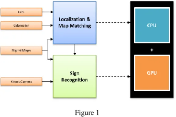
The target architecture is a combination of a multicore CPU and a many-core GPU, which is very likely to take place in a production vehicle environment as a unified computing platform in the near future. Both modules run on the same platform. The system overview can be seen in Fig. 1.
Figure 1 System overview
Both particle filter-based localization and map matching and template matching based sign recognition are computationally intensive applications where high success rates and real-time performance cannot both be achieved simultaneously using sequential implementations. The proposed system achieves both targets by employing parallelization on a hybrid multicore/many-core architecture.
We consider a multi-hypothesis localization and map matching algorithm where map topology information is used in terms of route-ability as the likelihood calculation in the particle filter to increase map matching performance, at the same time further increasing the computational cost of the algorithm.
We first characterized the execution profile of the particle filter algorithm for the different number of particles using a sequential implementation. Critical function blocks in terms of execution time were identified. We also investigated the effect of the number of particles employed by the algorithm on the error rate of localization and map matching. We then mapped the algorithm to the multicore CPU and the GPU platforms to accelerate bottlenecks and to see if the required speedups are realizable.
For our template-matching based sign recognition algorithm, which can be applied to a wide range of traffic signs, we employed a similar approach; we first observed detection rates using the Kinect sensor and recognition rates with the map fusion, and we also characterized the execution profile using a sequential implementation of the algorithm. We then tested the parallel implementations on our test system having two 6-core CPUs and two 512-core GPUs with real video and positioning data captured in the vehicle environment under various road and lighting conditions.
In the rest of this paper, we first give information about related work in this area.
We then describe the particle filter-based localization and map matching algorithm and the sign recognition approach with map fusion. We give details about our parallel implementations for both modules. We continue with tests and experimental results. We finish with the interpretation of those results.
1.1 Related Work
Traffic sign recognition is one of the key components of advanced driver assistance systems and has been worked on for a long time in the intelligent vehicles domain. Although the appearance of the traffic signs was originally designed to be easily distinguishable from natural objects, the reliable, automated recognition of traffic signs, especially under adverse environmental conditions, remains a complex task.
Recent approaches tend to use a scheme of three stages: detection of sign candidates, classification of the candidates and tracking of the sign candidates over time. Many algorithms available in the literature generally differentiate in using different methods in the detection and classification stages [2]-[5].
There are also some attempts to enhance the performance of visible light cameras for sign recognition using infrared cameras [6]-[8]. They are limited to a subset of traffic signs and use expensive hardware, and the recognition rate is lower than the proposed system.
Most of the work done in this field so far has been strictly bounded by available computing capacity. However, recent developments in multicore and many-core architectures present a research challenge, also in this area, to meet real-time performance requirements with a parallel processing model. There are a very limited number of studies in the literature for parallel implementations of traffic sign recognition. [9] and [10] describe the detection and classification of traffic signs on an application-specific multicore processor. A real-time template-based approach for the recognition of speed limit signs using GPU computing is described in [11]. A feature-based speed limit sign detection system using a GPU is described in [12]. The studies cover only speed limit signs and do not include map integration.
We propose a generic template-based approach which can be applied to a wide range of traffic signs and the parallel implementation on a multicore CPU and GPU platform. Our approach uses a new sensor (Kinect) which provides both color and infrared images of the traffic scene, which enhances the detection stage, and we also propose using digital map information to augment template matching in the classification stage in order to increase the robustness of the recognition and to contribute to real-time performance.
Kinect has become very popular in a very short time since its launch in November, 2010, not only for playing games, but also, with its relatively low price, in robotics research for depth sensing and 3D vision. However, we have not yet encountered an application of Kinect in intelligent vehicles research.
Our approach employs a particle filter-based localization and map matching.
Particle filters are among the principal tools for the on-line estimation of the state of a non-linear dynamic system [13]. Particle filtering has been applied widely in applications in tracking, navigation, detection and video-based object recognition [14]. Although, in general, particle filtering methods yield improved results compared to other Bayesian filters, it is difficult to achieve real time performance as the algorithm is computationally intensive [15]. This has been a prohibitive factor for real-time implementations for many applications of particle filtering.
A number of methods for software and hardware implementations of particle filtering have been proposed in the literature. Special architectures [16], field- programmable gate arrays (FPGAs) [17], and SIMD processor arrays [18] have been utilized for various types of problems. Many of the GPU implementations are focused on low-level stream processing or OpenGL [19].
Although emerging multicore processors and GPUs are good candidates for parallel particle filter implementations, multicore implementations, especially using the GPU computing concept and the platforms and tools such as NVIDIA’s CUDA architecture, are still very recent and few. Some of the recent studies [20]- [21] utilize the general particle filter algorithm, but they differ significantly in their calculation of the likelihood phase. This variety also influence the approach used in parallelization.
Our work is a part of a research project addressing the challenge of meeting the real-time performance requirements of ADAS and autonomous vehicle applications by efficiently mapping them on multicore and/or many-core architectures, and, to our knowledge, this is the first parallelization effort of traffic sign recognition with map fusion using Kinect sensor and a particle filter targeted to localization and map matching using map topology.
2 Localization and Map Matching
2.1 Particle Filter
Particle Filters, also known as Sequential Monte Carlo (SMC) methods, are iterative methods that track a number of possible state estimates, so-called particles, across time and gauge their probability by comparing them to measurements.
We are considering a dynamic system with state xtat a given time t. The system model is a Markov process of the first order. We assume that the system state can only be tracked by measurements yt, which may be influenced by noise. The relation between measurements and system states is described by the measurement model.
The sampling importance resampling (SIR) algorithm is one of the most widely used sequential Monte Carlo methods. The SIR algorithm has following stages iterated over discrete time steps:
Sampling (Prediction): To follow the state during subsequent iterations, the system model is used to obtain a possible new state for every particle xti based on its last state xti1 where ut1 is measured inputs and vt1 unmeasured forces or faults:
1,
1 1
ti t t
i
t Ax Bu v
x i1,...,N (1)
Importance (Update): The measurement model is evaluated for every particle and the current measurements to determine the likelihood that the current measurement yt matches the predicted state xti of the particle. The resulting likelihood is assigned as a weight wit to the particle and indicates the relative quality of the state estimation:
),
|
1 (
i t t i t i
t w p y x
w i1,...,N (2)
At this point, when the particles are weighted, a state estimation can easily be obtained via various techniques, such as using the highest-weighted (highest- probability) sample, or using the weighted sum of the particles to get a mean- equivalent, or using the average of particles within some distance from the best particle.
iN it ti
t wx
xˆ 1 (3)
Resampling: If the number of effective samples fall below a certain value, resampling is required. Particles with comparatively high weights are duplicated and particles with low weights are eliminated. This can be done by calculating the number of effective particles Neff as follows:
i i t
eff w
N 2
) (
1 (4)
Effective sample size (ESS) is another metric to decide if resampling is required.
2.2 Particle Filter for Localization and Map Matching
For the vehicle localization problem, state is represented as a four-dimensional vector x = [Lon, Lat, Ɵ, L] where Lon, Lat, Ɵ and L stand for position, orientation and link or road segment on the map database, respectively.
Basically, the new location of the vehicle is predicted using the odometer data in the prediction stage and corrected by the GPS measurements and a map based likelihood function in the weight update stage. The operations performed in the main stages of the particle filter can be summarized as the following:
Prediction: The data coming from the odometer is used to measure vehicle displacement. The new location (Lon, Lat) of the vehicle is randomly calculated for each particle in the range of this displacement. This stage requires a high number of random number generations for the calculation of the new values of each state variable.
Weight Update: Weights are updated using the GPS readings first. The likelihood function is designed so that the particles that are within the error range of the GPS reading get higher weights. Then the weights are augmented with the map data by multiplying them with the probabilities derived from the map:
) topology (
) zone
1 p( p
w
wti it (5)
Two types of map attributes are used in the likelihood calculation. The first feature is the type of area where the particle resides on the map (road segment, building, parking area, etc.). The probability of being in a certain type of zone or road class (e.g. motorway, major road, local road, residential road, etc.) is calculated based on the speed of the vehicle (e.g., for a vehicle at a speed of 120 km/h, the relative probability of being on a motorway is chosen to be higher than being on a residential road).
The second feature of the map is the topology. Given the previous location of a particle, the probability of travelling to a new location on a certain road segment is calculated using the map topology. Possible reachable roads are searched in the road network in forward and backward directions for the distance travelled measured from the odometer. If the predicted location of the particle is found to be reachable, a high probability is assigned, otherwise a low probability is assigned (e.g., due to the connectivity, direction of traffic flow, turn restrictions, etc.).
Estimation: The location component of the system state is calculated as the weighted mean of each particle’s location information. Map matching is achieved by selecting the road segment with highest weight as the matched link on the map.
The flow of our particle filter algorithm for localization and map matching is shown in Fig. 2.
Figure 2
Particle filter localization and map matching
3 Sign Recognition
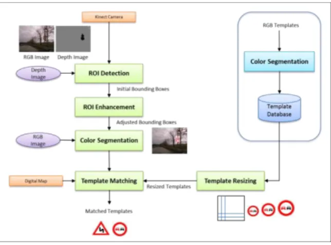
The proposed traffic sign recognition algorithm is implemented based on a template matching pipeline. The Kinect camera’s depth image output is used to determine candidate regions on the RGB image. A special color segmentation scheme is applied to candidate regions. Template matching is employed for classification. A distance is calculated between the candidate region in the source image and different sizes of template images in the template database based on a difference function. The template having the minimum distance is denoted as the matched or recognized sign. Fig. 3 summarizes the design of the algorithm and the following sections describe the stages of the sign recognition flow in detail.
Figure 3 Sign recognition algorithm
3.1 Template Database and Map-based Probabilities
A template database is created from the sign images. Each sign template has two versions, one with a white background, the other with a black background. When sign recognition is carried out under night conditions, templates with black background are needed. Templates are also converted to four colors by use of color segmentation. Only black, white, red and blue are preserved in the image.
We used an automatic resizing function according to the size of the region of interest found in the scene.
The localization and map matching algorithm determines the vehicle location and the map segment. By use of the matched segment, we can calculate map based probabilities for each sign in the database, considering different map contexts for various sign classes. Table 1 summarizes the sign classes and their respective map based context.
Table 1
Traffic signs and their respective map context
Sign Class Signs Map Context
Speed Signs Road Class, Speed Limit
Manoeuvres Manoeuvres (restrictions), One way information
and map topology
Bends Map topology, existence of a bend in the
driving direction is checked.
Junctions Map topology, existence of a junction and type
of junction is checked
School POI, existence of a school is checked.
Parking Road Class
3.2 ROI Detection with Kinect Sensor
The Kinect camera’s depth sensor consists of an infrared laser projector combined with a monochrome CMOS sensor, which captures video data in 3D under any ambient light conditions. When used in outdoor environment, we end up with a very effective function of Kinect; it detects reflective surfaces (signs in traffic) and thus makes region of interest (ROI) detection very easy and robust. Fig. 4 (a) and (b) show the RGB image and the depth image coming from Kinect camera for the same scene. The depth image shows the region of interest in the RGB image.
(a) Input RGB Image (b) Depth Image
(c) Initial and Enhanced ROIs (d) Color Segmented ROIs Figure 4
ROI detection with Kinect sensor
The initial bounding boxes are created by following the neighboring pixels within a given pixel tolerance. As seen in the Fig. 4 (c), the initial bounding boxes (green) are not perfect. There are several reasons for this. The IR camera and the RGB camera of the Kinect sensor have different fields of view and focal lengths.
The RGB camera has a wider field of view. This is why, when objects get closer to the image edge, the difference in pixel locations increases. The two cameras are separated from each other by 2.5 cm. Sometimes the pixel image coming from the IR camera does not cover the whole sign. Sometimes the two signs are so close (their distance is smaller than the pixel tolerance when calculating the bounding boxes) that only one bounding box is found for two signs. There may be some small bounding boxes caused by reflections coming from other surfaces. An algorithm has been developed to overcome these errors. The initial and enhanced ROIs are shown in Fig. 4 (c) in green and yellow rectangles, respectively.
3.3 Template Matching
For a better matching, color segmentation is applied to the regions of interest first.
All the colors in the image are segmented in four colors: red, blue, white and black. An example of color segmentation can be seen in Fig. 4 (d). After color segmentation, the templates are matched against the region of interests by computing the sum of the differences between pixel color values. For each region of interest, templates are resized based on the size of the bounding box before matching. Several template sizes with different aspect ratios are tried. Starting from corner of the region of interest, the difference between the template and the region of interest is calculated. The difference value is normalized according to the template size. The template with the lowest difference value is selected as the match.
3.4 Map Fusion
Template matching generates a likelihood measure for each sign. This measure is the distance between the template image and the camera image. Since we successfully detect the location of the sign on the camera image, the sign with the lowest distance value can be selected as the matched sign most of the time. But some of the signs are very similar to each other. Also, even if we find the location of the sign successfully, the camera image may not be clear. As a result of this, the algorithm returns very close likelihood results. When we fuse this information with the probabilities coming from the map, the correct sign can be selected. The recognition performance of our algorithm increases radically. Fig. 5 shows two examples of template matching results, with and without map fusion.
Template Matching without Map Fusion
Template Matching with Map Fusion
0,70 0,67 0,52 0,90
Template Matching without Map Fusion
Template Matching with Map Fusion
0,78 0,77 0,66 0,97
Figure 5
Sign recognition with map fusion
4 Parallel Implementations
4.1 Localization and Map Matching
Before attempting parallel implementations, we first characterized the execution profile of the particle filter algorithm for different number of particles using a sequential implementation. We see that the prediction and update sections dominate the execution time by a large margin. Therefore, those sections were selected as the first targets of parallelization in both platforms.
Particle filters heavily use random number generation. Our implementation uses the Mersenne-Twister random number generation algorithm. An existing implementation has been adopted for both the CPU and GPU platforms.
4.1.1 Multicore (OpenMP) Implementation
We used OpenMP programming model [22] for the parallelization of the predict and update sections of the particle filter on a multicore CPU. Since the same operations are repeated for all the particles in a loop for both the predict and update sections and the particles can be processed independently of each other, the iterations (effectively the particles) have been distributed among the cores. Each core therefore performs the prediction and update steps on a subset of particles.
The static scheduling mechanism of OpenMP is used for the predict part and dynamic scheduling has been employed for the update part, in order to have a better workload distribution among the cores since the complexity of map based operations for each particle in the update step can be different.
4.1.2 GPU (CUDA) Implementation
In our GPU implementation, we used the CUDA programming model [23]-[24].
This actually represents a hybrid (CPU+GPU) implementation of particle filter.
We implemented most of the main steps of the filter in C using CUDA Toolkit 3.2. The Prediction, Update, Estimation, and ComputeESS parts were implemented as kernels to run on GPU (device), where resampling part is run on CPU (host). The CUDA implementation flow is illustrated in Fig. 6.
Since the prediction and update parts of a particle filter work on particles independently, a separate thread is created for each particle on the GPU for the predict and update kernels. This is accomplished by using the appropriate execution configuration parameters, when the kernels are launched. Each thread determines which particle it should process via built-in variables, the thread block index, the thread index within its block, and the block size.
The states of particles are stored in the global memory, and during initialization both host and device memory are allocated for particles, and the initial particle data are copied to the device. The global memory is used to pass on data from one
kernel to the next. Map data is also transferred to the device memory during initialization. Each thread is enabled to use its own random number generator instance. Initial Twister states for the maximum possible number of threads are created on the host and transferred to the device memory at the initialization.
For the update kernel, measurement values are passed as parameters at the kernel launch for each iteration. The estimation part consists of the summation and normalization of the weights and the calculating weighted mean of the state variables. This part is divided into three separate kernels: summation, normalizeWeights and mean kernels. The division of the workload into separate kernels was necessary due to the fact that the only way to enforce synchronization between all concurrent CUDA threads in a grid is to wait for all kernels running on that grid to exit.
Figure 6
CUDA implementation of particle filter localization and map matching
For the summation kernel, the parallel prefix sum technique is used to calculate the partial sums within each block, and these partial sums are added to the global sum by using global atomicAdd operations. The normalizeWeight kernel is implemented similar to the predict and update kernels. Each thread adjusts its weight independently by using the sum value which is passed to it as a parameter at the kernel launch. The mean kernel and the computeESS kernel also use the parallel reduction technique similar to the summation kernel. After the estimation is completed, the estimated state variables are transferred to the host.
The amount of data transfers between the host and device has been kept very small for the iterations where resampling is not required. If resampling is required, the current weights of the particles are transferred to the host, and the surviving particles are calculated on the host.
4.2 Sign Recognition
The execution time profile of the sequential implementation shows that the template matching process has the highest computational cost, more than 98 percent of the total execution time. This has been chosen as the target for parallelization. The matching process for each video frame involves the following parameters:
r number of ROIs detected in the frame n number of templates in the template database
m number of different sizes for each template to be used for matching s number of different starting positions for matching in each ROI w width of template in pixels
h height of template in pixels
Assuming (x,y) denotes the starting search image coordinates and (i,j) denotes the template image coordinates, the time required for the matching process for each frame can be defined as the following:
r n m s hi wj Diff x i y j i j
t 0 0 ( , , , ) (6)
Three parallel implementations have been developed for multicore CPU, single GPU and multi GPU architectures. For all cases, the detection stage is performed on the host sequentially, which is performed very fast with the help of the Kinect camera.
4.2.1 Multicore (OpenMP) Implementation
The multicore CPU implementation is performed using the OpenMP programming model. The matching operations for each template are distributed among the multiple CPU threads. The number of threads is determined by the maximum number of cores in the system. For each region of interest, the work is distributed on a templates basis.
4.2.2 GPU (CUDA) Implementation
The GPU implementation is performed using CUDA. The pixel level matching operations are designed to run on GPU in parallel. A kernel (matching kernel) has been implemented to perform the matching of a ROI to a resized template and produce the sum of differences (SAD) values. A separate thread is created for each pixel operation when the kernel is launched. Initially, all memory allocations are done for RGB images, resized templates and SAD values on both host and device. For each video frame, detection is performed on the host and ROIs are found. If at least one ROI is found in the depth image, the RGB image is copied to the device memory. Each ROI found in the frame is matched against different sizes and starting positions of all the templates by calling the matching kernel.
Resizing is done on the host, each template is resized based on the size of ROI, and resized templates are copied to the device memory before launching the matching kernel. Since the RGB image and the resized templates are already in the device, the kernel is then called with only the corner positions of the region of interest, the template number and the size of the template.
Since the number of pixels in region of interests are relatively small (e.g. 49x48) compared to whole images (640x480), to be able to achieve maximum occupancy of GPU cores, the matching kernel is designed to compute SAD values for all different starting positions (4x5) of a resized template each time it is launched. So each launch of the matching kernel performs 20 matching operations in parallel at the template level in addition to the pixel level parallelism (e.g., for a 44x40 pixel region of interest, 35200 threads are created instead of 1760, corresponding to 138 blocks instead of 7 blocks, respectively).
Kernels for each different size of the same template are launched concurrently using different streams. Concurrent kernels is a scheduling convenience allowing different streams of the same context to run simultaneously. It enables to increase the efficiency if there are inefficient low block count kernels, mostly by reducing idle streaming multiprocessor count while kernels are finishing up. The maximum number of concurrent kernels that can be executed on a Fermi GPU is 16. The number of different sizes (4x4) to be matched for each template is also 16 in our implementation. This enables the matching of all different sizes of a template to be launched concurrently. SAD values are accumulated in the global memory by using AtomicAdd operations. For each template, after calling the kernels for all variations, the SAD values are copied back from the device to host, and for each region of interest, the SAD values are processed to determine the result of recognition. The flow of the implementation is shown in Fig. 7.
Figure 7
CUDA implementation of sign recognition algorithm
4.2.2 Multi GPU Implementation
The multi GPU solution can be used with any number of GPUs. This is also a hybrid implementation. Five CPU threads are used. The detection thread gets the depth, and RGB image frames, perform the detection phase, for each ROI found in the depth image, resizes the templates based on the size of ROI and puts the related data into a queue to be passed to a GPU to perform the matching. The Dispatcher thread keeps track of the availability of GPUs and determines the target GPU that will process the next ROI data and assigns the device number to the data slot in the queue. Each GPU has to be controlled by one CPU thread in multi GPU programming with CUDA Toolkit 3.2. Two matching threads are responsible for controlling the GPUs, including sending the required data (i.e.
RGB image, ROI boundary, resized templates) to the device, launching the matching kernels concurrently, receiving the SAD values from the device and storing them into the results queue. The recognition thread processes the SAD values and determines the sign recognized for each ROI. The implementation details are depicted in Fig. 8.
Figure 8
Multi GPU sign recognition implementation
5 Experiments
We have tested performance of our parallel implementations using real video, GPS and odometer data captured in six test routes comprising various road (highways, urban traffic, etc.) and lighting conditions (night/day, sunny/cloudy).
Parallelization tests were performed on our test platform, a dual processor HP® Z800 workstation having two Intel® Xeon® 5660 6-core processors running at 2.80 GHz and two NVIDIA® GeForce GTX580 graphics processing units.
The GTX580 GPU has NVIDIA’s new generation CUDA architecture called Fermi and has 16 streaming multiprocessors, each having 32 streaming processors, and thus in total has 512 processing cores. Hence, it is capable of running 512 threads simultaneously. Each core runs at 1.544GHz. Each streaming multiprocessor has 64KB configurable L1 cache. All cores shares a 768MB L2 unified cache and a 1512MB global memory.
5.1 Localization and Map Matching
We used one 6-core CPU and one 512-core GPU in our tests. Tests were repeated on each platform for different number of particles ranging from 256 to 128K. For the multicore CPU tests, we ran the OpenMP implementation with 6 threads. For the CPU+GPU tests, the block size was chosen as 256.
The OpenMP implementation provided approximately a 4.7x speedup with a theoretical maximum increase of 5.4x on a 6-core CPU. We observed similar speedups after the number of particles exceeds 4096.
With the CUDA implementation, we achieved increasing speedups of up to 75x when the number of particles reached 128K. We see that the performance of GPU is better exploited when the number of particles or threads is increased. The relatively low speedups for the smaller number of particles are mainly due to the low occupancy of streaming multiprocessors. Fig. 9 shows the execution times of sequential, multicore CPU and GPU implementations for different number of particles and the relative speedups.
Figure 9
Execution time and speedup comparisons of sequential and parallel implementations When we examine performance of kernels separately, we see that speedups can be as high as 150x for the predict kernel, where there are no data dependencies among threads and operations performed are almost identical for all threads. We see 100x speedups for the update kernel, where we observe the negative effect of branching and divergence on the performance since road network is traversed to a new location for some particles which causes different execution paths for threads.
We see speedups around 10x for the estimation and computeESS kernels, where synchronization requirements within blocks and global atomic operations reduce speedups. However, overall speedups achieved are sufficient for real-time localization and map matching using a high number of particles.
We examined the sensitivity of the localization and map matching performance to the number of particles to determine the optimum number. The error rate is calculated as the ratio of the number of wrong map matches to the total number of positions on the test routes. We see that the error rate decreases significantly until the number of particles exceeds 32K. Fig. 10 shows the error rates for two different routes.
Figure 10
Effect of number of particles on the error rate of map matching algorithm
5.2 Sign Recognition
Since detection of ROIs are handled by the the Kinect camera, detection is successful even in very bad lighting conditions. We have observed that the system can detect signs that can hardly be seen by human eye. Fig. 11 shows an example of a successful recognition at night. Table 2 summarizes success rates of detection and recognition for different route types. We see that map fusion improves recognition performance dramatically especially under night conditions.
(a) Input RGB Image (b) Recognized signs Figure 11
Successful recognition at night conditions Table 2
Detection and recognition rates for traffic signs using Kinect camera
Route Type Detection
Rate
Without map fusion
With map
fusion Improvement
Cloudy, Residential Roads - Urban 93% 84% 92% 9%
Sunny, Residential Roads - Urban 89% 71% 85% 20%
Cloudy, Main Roads 91% 71% 86% 20%
Cloudy, Connecting Roads- Rural 95% 50% 83% 66%
Night, Main Roads 94% 55% 88% 60%
Night, Residential Roads 92% 40% 80% 100%
Multicore CPU and GPU implementations were tested on the same platform. The average processing time for frames was measured and the execution time of sequential implementation was taken as a reference in the speedup calculations.
For each ROI, 16 (4x4) different starting positions, and for each template, 20 (4x5) different sizes, were used. Tests were performed with a template database having 52 templates. The recognition of each ROI involved 16,640 matchings.
Multicore CPU implementation were tested with different numbers of threads, ranging from 1 to 24. Speedups of up to 10.6x were achieved. We observed linearly increasing speedups until the number of threads reached the number of cores in the system. After that point, we observed that the speedups were not improved with the increasing number of threads, but rather stayed in the range between 8.7 and 9.7. The execution time at the maximum speedup was around 250ms corresponding to 4 frames per second. The linear speedups show that we can further increase frame rates when we have a higher number of cores in the system.
Speedups up to 18.1x and 35.2x were achieved on a single GPU and multi GPU tests, respectively. The execution times at the maximum speedups approximately correspond to 7 and 13 frames per second. For GPU tests, we used 256 threads as the block size. We observed that 100% occupancy was achieved. Speedups and execution times for all implementations are shown in Fig. 12.
Figure 12
Execution time and speedup comparisons of sequential and parallel implementations Conclusions
We introduced a real-time traffic sign recognition system with digital map fusion, and we examined parallel implementations and performance analysis on emerging multicore CPUs and GPUs. Test results show that up to 75 times speedups can be achieved for particle filter based localization and map matching on GPU over sequential implementation, and real-time performance is possible in the case of high computational cost of using map topology information. We showed that success of localization and map matching can be increased by employing a high number of particles where real-time performance can be achieved only by parallelization.
The speedups achieved for our sign recognition system show that the template matching based recognition approach with map augmentation, which is a simple but computationally intensive technique, can be used with real-time performance in the vehicle environment. We observed detection rates over 90% using the Kinect sensor and recognition rates over 80% for various road and lighting conditions. Test results show that the system performs very well even in night conditions. The proposed system is unique since it is not limited to certain sign types, can be used for recognition of wide range of traffic signs, can be used in
any lighting conditions, utilizes the Kinect sensor to achieve a good price/performance, and runs on commercially available parallel hardware. Our future work will include investigating the co-scheduling of other tasks that can run simultaneously on the same platform with sign recognition and localization while delivering required throughput and minimal affordable latency.
Acknowledgement
This research was supported by Bogazici University Research Fund, contract No.
5522.
References
[1] K. Par, and O. Tosun, “Parallelization of Particle Filter Based Localization and Map Matching Algorithms on Multicore/Manycore Architectures”, Intelligent Vehicles Symposium (IV), 2011 IEEE, pp. 820-826, June 2011 [2] B. Hoferlin and K. Zimmermann, “Towards Reliable Traffic Sign
Recognition”, IEEE Intelligent Vehicles Symposium, pp. 324-329, June 2009
[3] A. de la Escalera, J. Ma Armingol, M. Mata, “Traffic sign recognition and analysis for intelligent vehicles”, Image and Vision Computing, pp. 247- 258, Vol. 21, 2003
[4] C. Bahlmann et al., “A System for Traffic Sign-Detection, Tracking and Recognition Using Color, Shape and Motion Information”, IEEE Intelligent Vehicles Symposium (IV), pp. 255-260, June 2005
[5] J. Ban, M. Feder, M. Oravec, and J. Pavlovicova, “Non-Conventional Approaches to Feature Extraction for Face Recognition”, Acta Polytechnica Hungarica, Vol. 8, No. 4, pp. 75-90, 2011
[6] Weijie Liu, and Maruya, K., “Detection and Recognition of Traffic Signs in Adverse Conditions”, IEEE Intelligent Vehicles Symposium, pp. 335-340, June 2009
[7] Tsz-Ho Yu, Yiu-Sang Moon, Jiansheng Chen, Hung-Kwan Fung, Hoi-Fung Ko, Ran Wang, “An Intelligent Night Vision System for Automobiles”, IAPR Conference on Machine Vision Applications, May 2009
[8] B. Kuljic, J. Simon, and T. Szakall, “Pathfinding Based on Edge Detection and Infrared Distance Measuring Sensor”, Acta Polytechnica Hungarica, Vol. 6, No. 1, pp. 103-116, 2009
[9] R. Ach, N. Luth, A. Techmer, “Real-Time Detection of Traffic Signs on a Multi-Core Processor”, IEEE Intelligent Vehicles Symposium, pp. 307- 312, June 2008
[10] R. Ach, N. Luth, A. Techmer, A. Walther, “Classification of Traffic Signs in Real-Time on a Multi-Core Processor”, IEEE Intelligent Vehicles Symposium (IV), pp. 313-318, June 2008
[11] V. Glavtchev, P. Muyan-Ozcelik, J. M. Ota, and J. D. Owens, “Feature- based Speed Limit Sign Detection Using a Graphics Processing Unit”, Intelligent Vehicles Symposium (IV), 2011 IEEE, pp. 195-200, June 2011 [12] P. Muyan-Ozcelik, V. Glavtchev, J. M. Ota, and J. D. Owens, “A
Template-based Approach for Real-Time Speed-Limit Sign Recognition on an Embedded System Using GPU Computing”, Proceedings of the 32nd DAGM conference on Pattern recognition, pp. 162-171, 2010
[13] N. J. Gordon, D. J. Salmond, and A. F. M. Smith, “A Novel Approach to Nonlinear/Non-Gaussian Bayesian State Estimation,” IEE Proceedings on Radar and Signal Processing, Vol. 140, No. 2, pp. 107-113, 1993
[14] F. Gustafsson, F. Gunnarson, N. Bergman, U. Forssell, J. Jansson, R.
Karlsson, and P. Nordlund, “Particle Filters for Positioning, Navigation and Tracking”, IEEE Transactions on Signal Processing, Vol. 50, No. 2, pp.
425-437, February 2002
[15] D. Kocur, J. Gamec, M. Svecova, M. Gamcova and J. Rovnakova,
“Imaging Method: An Efficient Algorithm for Moving Target Tracking by UWB Radar”, Acta Polytechnica Hungarica, Vol. 7, No. 3, pp. 6-24, 2010 [16] Bolic, M., “Architectures for Efficient Implementation of Particle Filters”,
PhD Dissertation, Stony Brook University, August 2004
[17] M. Happe, E. Lübbers, and M. Platzner, “A Multithreaded Framework for Sequential Monte Carlo Methods on CPU/FPGA Platforms”, Proceedings of the 5th Inte Workshop on Reconfigurable Computing: Architectures, Tools and Applications, pp. 380-385, 2009
[18] H. Mederios, J. Park, and A. Kak, “A Parallel Implementation of the Color- based Particle Filter for Object Tracking”, IEEE Computer Society Conference on Computer Vision and Pattern Recognition Workshops, pp.
1-8, June 2008
[19] G. Hendeby, R. Karlsson, and F. Gustafsson, “Particle Filtering: The Need for Speed”, EURASIP Journal on Advances in Signal Processing, 2010 [20] J. F. Ferreira, J. Lobo, and J. Dias, “Bayesian Real-time Perception
Algorithms on GPU”, J. Real-Time Image Proc., Springer, 2010
[21] M. A. Goodrum, M. J. Trotter, A. Aksel, S. T. Acton, and K. Skadron,
“Parallelization of Particle Filter Algorithms”, Proc. of 3rd Workshop on Emerging Applications and Many-core Architecture (EAMA), 2010 [22] B. Chapman, G. Jost, and R. van der Pas, “Using OpenMP, Portable Shared
Memory Parallel Programming”, The MIT Press, 2007
[23] J. Nickolls, W. J. Dally, “The GPU Computing Era”, IEEE Micro, pp. 56- 69, March-April 2010
[24] NVIDIA CUDA Programming Guide 3.2, 2010