Morphology of fl uvial levee series along a river under human in fl uence, Maros River, Hungary
Tímea Kiss
a,⁎ , Márton Balogh
a, Károly Fiala
b,⁎ , György Sipos
aaDepartment of Physical Geography and Geoinformatics, University of Szeged, Szeged 6722, Egyetem u. 2–6, Hungary
bLower Tisza District Water Directorate, Szeged 6720, Stefánia 4, Hungary
a b s t r a c t a r t i c l e i n f o
Article history:
Received 17 July 2017
Received in revised form 8 December 2017 Accepted 9 December 2017
Available online 12 December 2017
The development and morphometry offluvial levees reflect the connection between channel and overbank processes, which can be altered by various human activities. The aims of this study are to investigate the morphology and spatial characteristics offluvial levees and evaluate the role of some local- and catchment-scale human activities on their medium-term (150 years) development. This study applies LiDAR data along a 53-km-long reach of the Maros River in Hungary.
Sixfluvial levee types are identified based on the beginning and end of their evolution. These levee types were generated by local nineteenth century channel regulation works (cutoffs) and mid-twentieth century channel narrowing, which was caused by gravel mining and water impoundment in the upstream sections. However, other human activities also influenced the development of activefluvial levees because their horizontal evolution could have been limited by embankedflood-protection levees or the widening of low-lyingfloodplain benches that were generated by channel narrowing. Additionally, revetment constructions influenced their vertical parameters as higherfluvial levees developed along thefixed banks. Generally, the older activefluvial levees are wider, while the younger active levees are narrower with steeper slopes but not always lower. On the low- lyingfloodplain levels (benches), the youngestfluvial levees evolved quite rapidly and consist of coarser material.
Currently, only 9.8- to 38-year return-periodfloods could cover thefluvial levees, contributing to their evolution.
This fact and the development offluvial levee series with two-three members reflect a gradual decoupling of the channel from thefloodplain.
© 2017 Elsevier B.V. All rights reserved.
Keywords:
Fluvial levee Human activity
Channel-floodplain connection LiDAR
1. Introduction
Fluvial (natural) levees are common features along low-gradient channels (Nanson and Croke, 1992) that control the relationship between instream and overbank processes (Brierley et al., 1997). Fluvial levees are ribbon-like accumulation forms that rise above thefloodplain (Nanson and Croke, 1992; Smith, 1996) along concave banks (Fisk, 1947; Allen, 1965; Zwolinski, 1992) and next to straight reaches of different channel patterns (Brierley et al., 1997). Their development is connected tofloods, when the velocity decreases because of a rapid drop in the water column and because of the increased roughness from vegetation (Hughes, 1997; Piégay et al., 2003; Dufour and Piégay, 2005; Steiger et al., 2005). Thus, coarse grains accumulate along the banks to formfluvial levees, whilefiner grains can aggrade on the distal portion of thefloodplain (Wolman and Leopold, 1957;
Middelkoop and Asselmann, 1998; Wolfert et al., 2002; Kiss et al., 2004; Sándor, 2011). Fluvial levees appear along laterally stable sections
(Nanson and Croke, 1992); therefore, if thefluvial system loses its equi- librium, these levees can also be altered (Adams et al., 2004; Abate et al., 2015). However, only a limited amount of research has been conducted on the modification offluvial levees because of human disturbances (Klasz et al., 2014).
A morphometric analysis offluvial levees revealed that narrower (and younger) forms tended to be steeper and that the farther the sediments were transported from the bankline, the gentler the slope of thefluvial levee became (Cazanacli and Smith, 1998). However, contradictory results were observed when the morphology offluvial levees was correlated to the hydromorphological parameters of the adjacent channel andfloodplain. According toHudson and Heitmuller (2003), the levees' size corresponded to the sediment transport charac- teristics and medium-term (100–1000 years) changes in the flow regime. Higherfloods usually have higherflow velocity and sediment discharge and thus can create larger levees (Brown, 1983; Chalov, 2004; Keen-Zebert et al., 2013). The size offluvial levees is also influ- enced by the slope of the river (Fryirs and Brierley, 2012), its discharge (Taylor, 2002; Sorrells, 2012), the width and configuration of theflood- plain (Pierik et al., 2017), and the density of riparian vegetation (Steiger et al., 2005). However, in contrast to earlier studies,Adams et al. (2004)
⁎ Corresponding author.
E-mail addresses:kisstimi@gmail.com(T. Kiss),metusmail@gmail.com(M. Balogh), fialak@ativizig.hu(K. Fiala),gysipos@geo.u-szeged.hu(G. Sipos).
https://doi.org/10.1016/j.geomorph.2017.12.014 0169-555X/© 2017 Elsevier B.V. All rights reserved.
Contents lists available atScienceDirect
Geomorphology
j o u r n a l h o m e p a g e :w w w . e l s e v i e r . c o m / l o c a t e / g e o m o r p h
concluded that the dimensions of levees were independent of the chan- nel size, bankfull channel area, or grain size, although their morphology was controlled by the position of thefluvial levee on the meander, chan- nel age,flood frequency, and vegetation type and density. According to Hudson and Heitmuller (2003), the width offluvial levees was inversely correlated to the radius of the curvature of meanders.Klasz et al. (2014) hypothesised that the height offluvial levees corresponded to the width of the adjacentfloodplain: highfluvial levees developed in wideflood- plains, while low levees formed in narrowfloodplains because of water backflow into the main channel. Contradictory ideas exist regarding the factors that influence the spatial development of levees because few stud- ies have been conducted on the morphology offluvial levees and because they represent quite different environments. Catchment-scale and local human activities can alter all the above parameters (e.g.,flood character- istics, channel geometry, transported sediment,floodplain width), so our hypothesis is that the evolution and dimensions offluvial levees could be altered by anthropogenic activities, especially on rivers that have been in- tensively regulated, such as the Maros River in Hungary.
Fluvial levees show large variations in dimension and diverse grain- size distributions, indicating an intermediate nature between the channel and thefloodplain (Cazanacli and Smith, 1998), as their material is coars- er than the sediments of thefloodplain butfiner than the bedload (Brierley et al., 1997). At the beginning of development, coarse sediment is transported from the channel and deposited within a short distance, initially forming narrow, steep, and coarse-grainedfluvial levees. Fluvial levees become higher andfiner grained because of ongoing overbank ag- gradation, and eventually only largefloods can overflow them (Cazanacli and Smith, 1998). The farther the sediments are transported from the bankline, the lower the slope of afluvial levee becomes (Cazanacli and Smith, 1998).
Considering the rate offluvial levee aggradation,Smith and Pérez- Arlucea (2008)found that thickerfluvial levee material was deposited at sections where the channel widened after a largeflood, whereas thin- ner deposits occurred along aggrading or slightly enlarging channel sec- tions.Xu (2002)found a negative correlation between the vertical deposition rates of the riverbed and thefluvial levee. Over decades and centuries, the height increase (0.6–2.3 mm/y) offluvial levees has been quite slow in various climatic zones with local human activity (Stevaux and Souza, 2004; Makaske et al., 2009; Trimble, 2009); how- ever, as much as 0–70 cm of levee material could be deposited during largefloods (Smith and Pérez-Arlucea, 2008; Sándor, 2011). Under natural conditions, this aggradation is balanced by erosion and lateral channel migration. However, if the channel is stabilised, the height increase offluvial levees can be as much as 11.0 mm/y on average (Klasz et al., 2014). The mismanagement of afloodplain can increase the density of vegetation, resulting in acceleratedfluvial levee develop- ment in a narrowing strip along the channel (Sándor, 2011). The rate offluvial levee development can also be accelerated in connection with increased sediment load from a mining area (James et al., 2012).
The horizontal dimensions offluvial levees vary from metres to sev- eral kilometres, while their vertical parameters vary from centimetres to metres (Allen, 1965) depending on the hydromorphological charac- teristics of the river. Fluvial levees are vertically small landforms, so pre- cise surveys by classical topographical mapping are difficult; in addition, field surveys of large and densely vegetatedfloodplain areas can be very laborious. In most previous studies, fewfluvial levee profiles were analysed (Cazanacli and Smith, 1998; Adams et al., 2004) or studied on maps and aerial photographs (Hudson and Heitmuller, 2003);
alternatively, the depth of levee material was measured along a reach after a singleflood (Smith and Pérez-Arlucea, 2008; Sándor, 2011).
High-resolution LiDAR data have become widely available so that scien- tists could obtain fast and accurate terrain measurements across large areas (Notebaert et al., 2009; Wierzbicki et al., 2013; Klasz et al., 2014;
Palaseanu-Lovejoy et al., 2014).
All these studies refer to single ridges but not to series offluvial levees, although they appear in succession along the Maros River in
South Hungary. Furthermore, thesefluvial levee series have developed along a section that is under various human influences. Among the local engineering works, artificial cutoffs, revetments, and embanked levees have been constructed; while inchannel gravel mining and water reten- tion have been conducted in more upstream sections. These engineering measures offer a unique possibility to study the role of anthropogenic dis- turbances onfluvial-levee development. Additionally, a new LiDAR data set (2014) provides a great opportunity to identify and morphologically evaluatefluvial levees along a 53.7-km-long reach of the Maros River.
The aims of this study are to investigate the spatial characteristics of thefluvial levee series and evaluate the role of reach-scale (e.g., cutoff, revetment, and embanked levee constructions) and catchment-scale (e.g., water retention and inchannel gravel mining) human activities on their development. These upstream human influences combine and influence the development of fluvial levees through channel narrowing andfloodplain-bench formation. Our specific goals are to (i) identifyfluvial levees on the embankedfloodplain, (ii) measure their horizontal and vertical parameters, reveal changes in their (iii) temporal and spatial characteristics and (iv) grain-size distribution, and (v) evaluate the role of human activities in their evolution. This study contributes to our understanding of medium-term (150 years) fluvial-levee development along a highly altered river channel and increases our knowledge regarding the changing linkage (coupling) between channels and theirfloodplains.
2. Study area
The Hungarian Marosfloodplain was studied in detail along a 53.7-km-long section from Nagylak (Nadlac) to Szeged (Fig. 1). The Maros constitutes the border between Romania and Hungary along the upstream section (53.7–28.0 km; units 1–8) and thenflows entirely within Hungary until its confluence with the Tisza River (28–0 km, units 9–31). Thus, the Hungarian LiDAR survey covered only the northern portion of thefloodplain along the upstream section, whilefloodplains on both banks were analysed in the downstream section.
The study area stretches across the Quaternary alluvial fan and the adjacentfloodplain of the Maros River (Kiss et al., 2011, 2014), and these macroforms influence the slope conditions of the river and thus the depositional environment in the embankedfloodplain (Kiss et al., 2011; Sümeghy, 2014). The uppermost section (units 1–8) of the study area is located on the alluvial fan, where the channel slope is the steepest (0.00038), and then the channel slope on the front of the fan (units 9–11) decreases (0.00022). The next geomorphological macroform is the secondary alluvial fan (12–20 units, channel slope:
0.00012), which developed between the embankedflood-protection levees (Kiss et al., 2011). After leaving the area of the alluvial fan, the riverflows across its naturalfloodplain (units 21–24, slope: 0.00005) andfinally reaches the outlet (units 25–31, slope: 0.00002) near the confluence with the Tisza River. Thus, the channel slope decreases by a factor of 18 along the 53.7-km-long studied section of the Maros.
Hydrological data from the Makó gauge station have been collected since the late nineteenth century, so the zero point of thefluviometer was set at the lowest monitored stage at that time; negative values have also been recorded because the channel was incised (Fig. 2A).
Since the beginning of these measurements, the water stages (−114–618 cm) and the discharge values (21–2450 m3/s) varied within a large range (Sipos et al., 2007). The discharge values of the yearly lowest stages reflect the inchannel processes. The discharge of the yearly lowest stagesfitted to a line in the 1900s to 1930s (Fig. 2B). The data shifted downward in the 1940s to 1970s, indicating inchannel aggradation. In the 1980s to 2000s, the data shifted upward (e.g., greater discharge values belong to the same stage), indicating incision and an increase in the cross-sectional channel area. Since the early 1980s, the annual maximum, mean, and lowest stages decreased by 11–35%. These hydrological changes in the late twentieth century were probably linked to increased water impoundment on the catchment and active inchannel gravel
mining in Romania ca. 70–120 km upstream of the studied section (Urdea et al., 2012; Kiss et al., 2017).
Understanding theflood history is crucial when developingfluvial levees. The bankfull level (350 cm, ca. 730 m3/s) is applicable only to the gauge site because of the considerable slope changes along the Maros. In the nineteenth to twentieth centuries, floods lasted for 6–21 d/y; however, in recent decades, overbankflows lasted for only 1–1.5 d/y or did not occur at all (Kiss, 2014). The recurrence interval of the bankfull stage based on the long-term (116 years) record is 2.3 years (Fig. 3). Floods in the Maros and Tisza rivers usually coincided, so thefloods in the Maros were naturally impounded by the Tisza, which influenced theflow conditions and sediment deposition along its lower, ca. 28-km-long section (Kiss et al., 2011); however, no data
exist regarding the influence of this impoundment on theflow velocity or sediment transport.
The Maros has considerable sediment discharge. The only measure- ments were conducted byBogárdi (1971), according to which the mean suspended load is 265 kg/s (8.3 million t/y) and the bedload is 0.9 kg/s (28,000 t/y). The bedload is dominated byfine gravel (2–4 mm) in the upstream section (1–11 units) but by sand in the downstream section (0.4–0.7 mm;Laczay, 1975). Therefore, very intensive (1.2–2.5 cm/y) vertical accumulation characterised thefloodplain from the mid- nineteenth until the mid-twentieth centuries, around the time of the cutoffs and embanked levee constructions (Oroszi et al., 2005; Kiss et al., 2011). This phenomenon can be explained by the intensive wid- ening and deepening of the artificial channel sections, which increased Fig. 1.The morphology offluvial levees was studied on thefloodplain of the Maros River, which was divided into 31 units between Nagylak and Szeged. Sediment samples were taken from four (I–IV) sections. a: River; b: embankedfloodplain; c: revetment; d: artificial cutoff; e: limit of the geomorphological macroform; f: unit and its number, g: country border;
h: settlement; i: sampling site (I–IV), j: drilling point; k: gauge station.
Fig. 2.Annual maximum, mean and lowest stages that were measured at the Makó gauge station (A), where the“0”point of thefluviometer was set arbitrarily. Correspondence between the yearly lowest stage and its discharge (B).
the sediment transport and accelerated aggradation on the narrower embankedfloodplain. In the second half of the twentieth century, overbank aggradation became limited because of shorter floods, channel narrowing, and incision (Oroszi and Kiss, 2004; Blanka and Kiss, 2006).
On the Maros River, embanked levee constructions began in the 1850s (Ihrig, 1973). These features were built simultaneously with channel regulations and along the nineteenth-century meanders, so the width of the embankedfloodplain varies (0.4–3.8 km). The up- streamfloodplain of the study area (units 1–9) is wider (1.0–3.8 km), while the lower area (units 10–31) is much narrower (0.4–1.8 km;
Fig. 1). Within the frame of channel regulations (1840–1871), 24 mean- ders and channel fragments were cut off in the study area (Fig. 1;
Laczay, 1975). These cutoffs affected the channel in units 5–31. A 9-km-long channel fragment was cut off close to the conjunction, so a new, sinuous artificial channel was created here (units 25–31). During regulation works, the increased slope accelerated bank erosion and channel incision (ca. 1.0 m), which combined with the increased sediment transport to create islands and inchannel bars, so an island- braided channel pattern developed along the upstream section (units 1–11). Meanwhile, the lower section downstream of Makó (units 12–31) remained sinuous. Since World War I, the upper section of the study area has constituted the border between Romania and Hungary, so engineering works were not allowed here. However, stone revet- ments were built (1946–1958) along an 18.3-km stretch to stabilise the banks within the 28-km-long lower section (units 12–31) (Sipos, 2006). The number of groynes is negligible.
In addition to these local-scale engineering works, catchment-scale and upstream human activity has influenced the development of the study area. In Romania, inchannel gravel mining between Lipova and Arad (ca. 70–120 km upstream of the study area) was intensive be- tween the 1960s and 2000s, which resulted in 2.6–6.8 m of incision within the mined section. The incision propagated downstream along the upstream portion of the studied section (units 1–11), measuring 1.2 m on average (Kiss et al., 2017). Meanwhile, the Tisza River was also regulated, and its channel was incised by 2–2.5 m (Ihrig, 1973;
Szlávik, 2000), which propagated upstream along the Maros. This headward incision combined with the incision that was propagating from upstream, so the incision along the lower section (units 12–31) was 1.9 m on average (Kiss et al., 2017).
3. Methods
3.1. Measuring the morphometric parameters
A digital terrain model (DTM) that was based on a LiDAR survey (provided by the Lower Tisza District Water Directorate) was applied to identify and measure the morphometric parameters offluvial levees.
This LiDAR survey was conducted in the winter of 2014 to minimise the effects of vegetation on the resulting elevation data. The vertical accura- cy of the DTM is ±0.1 m based on the resurveying of 525 points along the entirefloodplain. The DTM covers an area of 96 km2and has a resolution of 4 m2. The morphological measurements were performed with the ArcGIS 10.2 software.
On the DTM,fluvial levees appeared as almost continuous features along slightly sinuous bends but alternated with point bars along meandering sections; therefore, their lengths were not measured. How- ever, each bend had its ownfluvial levee, so the studied reach of the Maros was divided into 31 units (bends). The boundaries of the units were perpendicular lines to the banks across the inflection points of straight sections between the bends (seeLaczay, 1982). To locate the narrowing sections, the banklines were delineated on the third Hungar- ian Military Survey (created in 1881 shortly after the channel regula- tions) on geocorrected aerial photos from 1953 and the LiDAR survey (2014). The channel width was measured at every 100 m along the cen- tre line of the river. The width changes were calculated in percentages (%) compared to the beginning of the periods (1881–1953 and 1953– 2014). Floodplain surfaces (benches) were identified as low-lying areas between the 1881 and 2014 banklines.
In each unit, the morphometry of thefluvial levees was measured along cross-sectional profiles on the DTM and drawn perpendicular to the centre line of the river across the highest point of afluvial levee.
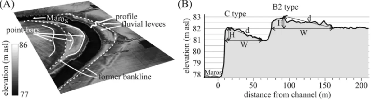
The boundaries of eachfluvial levee were defined by the bankline and the breaking point of the outer slope (Fig. 4) because the terrain on the distal portion of thefloodplain is almostflat (seeCazanacli and Smith, 1998; Adams et al., 2004). The width (W) of eachfluvial levee was measured between these boundaries, and the height (H) was mea- sured between the highest and lowest (distal) points of the natural levee. The slope (S) of the surface of eachfluvial levee (m/m) was calcu- lated from the ratio of the distance between the highest and lowest points along the outer slope (d) and relative height (H).
The elevation (m asl) of the highest points of thefluvial levees were known, so we could calculate the recurrence interval (RI) offloods, which could cover the levees and contribute to their aggradation. The RIwas calculated based on the annual highest stages (1901–2016) by applying the Gringorten formula (Searcy, 1959). The role offloodRIs influvial-levee development was only evaluated near the Makó gauge station (units 9–15) because (i) the water stage was only measured at Makó, (ii) considerable elevation changes occurred along the studied reach, and (iii) the water levels along the downstream section were influenced by the stage of the Tisza River. Therefore, the water-level elevation that covered a given levee was corrected by the slope of the river for this calculation.
Fig. 3.Recurrence interval (y) of the yearly highest stages of the Maros River at the Makó gauge station and the elevation (m asl) of the stages.
Fig. 4.Fluvial levees and point bars are distinguishable on the DTM of thefloodplain (A). The vertical parameters of thefluvial levees were measured along cross-sectional profiles (B).
3.2. Identifying thefluvial-levee types
The channel development of the Maros River is modified by cutoffs, channel narrowing, and revetments; whilefloodplain evolution is restricted by embanked levees that are located at various distances from the channel. Bankline changes from artificial cutoffs and channel narrowing terminated the development offluvial levees, and new fluvial levees began to develop along the new banklines. Thus, double or triplefluvial levees evolved, similarly to a series of point bars.
Altogether, sixfluvial levee generations are distinguishable along the studied reach of the Maros River (Fig. 5):
(A) Fluvial levees developed at the time of the nineteenth century river regulations with
(A1) continuous (active) development ever since;
(A2) terminated development because of channel narrowing since the 1950s; and
(A3) terminated development because of an artificial cutoff in the nineteenth century.
(B) Fluvial-levee development began during the nineteenth century river regulations when a cutoff was built, andfluvial levees began to develop along the new artificial channel with (B1) continuous (active) development since that time; and.
(B2) terminated development because of channel narrowing since the 1950s.
(C) The youngest, activefluvial levees began to develop when the channel became narrower (since the 1950s), and the evolution of a newfluvial levee began on the lowfloodplain benches.
3.3. Grain-size analysis of thefluvial levees
Materials from differentfluvial-levee types were sampled to evaluate the downstream variability in the grain size. Fluvial levees were selected along the straight upstream section (units 3 and 8–9), middle section (units 12 and 15) and downstream section (units 19, 14, and 26) of the Maros. These sediment samples (19) were collected on the highest points of the landforms from the uppermost sandy layer, where this material was probably deposited during their active evolution.
Additionally, each activefluvial-levee type was sampled along their entire depth to evaluate the grain-size changes during the evolution of the levees in the middle section of the river. Sediment samples (59) were collected by a Pürckhauer auger at 10-cm intervals. The grain-size
distribution of the samples was measured by the MasterSizer 3000 and Hydro LV module (Malvern Instruments) and evaluated by applying the Gradistrat software. The sediment profiles were dissected into zones and subzones based on similarities and differences in the grain size.
4. Results
4.1. Channel width change and bench formation
According to earlier studies (Sipos, 2006; Kiss et al., 2017), the channel has been narrowing since the 1950s, most intensively (12–15 m/y) in the 1950s to 1960s (Blanka et al., 2006). Low-lyingfloodplain benches could be formed during narrowing (Erskine and Livingstone, 1999; Haney and Davis, 2015). The developed benches create space for type Cfluvial levees, while the evolution of olderfluvial levees terminated (types A2 and B2).
This channel narrowing was studied in detail.
The studied 53.7-km-long reach of the Maros River became consider- ably narrower over the last 130 years (Fig. 6), with the average width de- creasing by 26% (1881: 155 m; 2014: 115 m). This width reduction has been more intensive since 1953. Between 1881 and 1953, the channel width only slightly changed, becoming narrower by only 2% on average (1881: 155 m; 1953: 152 m); however, narrowing became the dominant process after 1953. The average channel width has decreased by 24% since 1953 (1953: 152 m; 2014: 115 m), a mean narrowing rate of 0.6 m/y. This narrowing affected 88% of the studied reach. The most narrowed sections appeared to be in the upstream section (units 1–11), where the average narrowing was 26%. The greatest width reduction was 70% (1953:
251 m; 2014: 76 m) in unit 1, which is the uppermost unit and is situated closest to the gravel-mining area. The most intensive narrowing characterised the meandering and braided sections (units 1–21), while the channel width of the bends on the slightly sinuous downstream section (units 22–31) remained the same or even increased at the apexes of some bends.
This intensive channel narrowing created new, 20–130 m wideflood- plain surfaces (benches) that were suitable forfluvial levee development, although at lower (by 0.3–1.9 m) elevation.
4.2. Horizontal and vertical dimensions of thefluvial levee types
The LiDAR-based DTM on thefloodplain of the Maros River enabled us to identify 0.2–3.1 m highfluvial levees. One third (36%) of the studied forms belonged to type A (Table 1). The type A1fluvial levees
Fig. 5.Temporal changes from various human activities on the studied reach of the Maros and the resultingfluvial levee types. The bars indicate the timing of implementation and the active evolution of afluvial levee, while the broken bars refer to uncertain transformation.
developed over centuries and thus were the widest (Wmean: 441 m) and highest (Hmean: 1.8 m) forms in the study area (Fig. 7) but had the lowest slope (Smean: 0.0052). The evolution of type A2fluvial levees continued for a long time but was terminated by channel narrowing in the mid-twentieth century; therefore, these levees had narrower (Wmean: 173 m) and lower (Hmean: 1.4 m) features than the type A1 le- vees. The largest number of oldfluvial levees belonged to type A3. Their width was similar to those of the A2 levees (Wmean: 187 m), but their average height (Hmean: 1.1 m) was the lowest of the A types because these levees moved relatively farther from the active channel during the last ca. 150 years as the adjacent meanders were cut off. The spatial distribution of these types was determined by the spatiality of the nine- teenth century regulation works (Fig. 8). The type A1 and A2fluvial levees remained where the meanders of the Maros were not very sharp and thus were not cut off. Such unmanaged units were located in the upstream (units 1–3) and middle sections (units 10–19). The evolution of the type A3 levees was terminated by cutoffs, so these levees were located where the channel was straightened; thus, these levees could be found behind the members of type B.
The type Bfluvial levees (40% of the identified landforms) developed since the nineteenth century cutoffs and thus formed along the artificial, usually straight or slightly sinuous channel sections (Fig. 8). These le- vees were almost as wide and as high landforms as thefluvial levee types A2 and A3 (Fig. 7), although they have steeper slopes (by 38%).
The members of the actively developing type B1 were higher and steeper (Hmean: 1.7 m, Smean: 0.0159) than the type B2fluvial levees (Hmean: 1.5 m, Smean: 0.0084) because the development of the latter was terminated by channel narrowing. Generally, the type Bfluvial levees were higher along the wider channel sections because lateral erosion was more intensive here and the channel material could be de- posited along the banks. As the channel of the Maros was straightened in the upper section (units 5–12) and downstream of the no. 20 unit, type B1 and B2fluvial levees appear along these sections.
The members of type C constituted 12% of thefluvial levees. These levees were the youngest landforms because they evolved on the new low-lyingfloodplain surfaces that formed after channel narrowing (Figs. 6 and 8). Although these forms were the narrowest (Wmean: 46 m), they were high (Hmean: 1.6 m) and thus had the steepest slopes (Smean: 0.0428). Type Cfluvial levees were almost evenly distributed along the study area, as 75% of the studied Maros reach was intensively narrowed. Type C levees were missing near the confluence (units 25– 31) because the channel slightly widened at this location.
4.3. Morphological comparison of the activefluvial levee types
The studiedfluvial levees began to evolve at different dates, and their development ended in different fashions, so only the morphol- ogies of the still activefluvial levees (types A1, B1, and C) were compared in detail.
The oldest (A1)fluvial levees began to develop during preregulation times, so their mean width were ca. four times greater than those (B1) that developed after the river regulations and 18 times wider than the type C features, which began to develop on the low-lying benches after the 1950s (Figs. 7–9). However, their heights were quite similar, although the average values decreased with decreasing age. Thus, the greatest slopes characterised the type C levees, which were eight times steeper than the type A1 levees and more than three times steep- er than the type B1 levees.
Technically, no correlation existed between different parameters of the same type, although theR2values decreased with decreasing age.
For example, theR2value between the width and slope of the active fluvial levees was 0.76 for type A1 but only 0.56 for type B1 and only 0.19 for type C. The same tendency was also found between the width and height values of thefluvial levees.
4.4. Fluvial levee development andflood recurrence intervals
We could calculate the recurrence interval of the floods that overflowed the various levee types and contributed to their vertical ag- gradation based on the elevation of the highest point of eachfluvial levee. The type A1fluvial levees were covered by at least 490-cm-high floods (Fig. 10), which had an 11.9-year recurrence interval. The earlier the development of the type A levees terminated, the lower theflood level that was required for their inundation (A2: 462-cm stage and RI:
8.4 years, A3: 455-cm stage and RI 7.8 years). The type B levees were located along artificially straightened, higher energy sections and had already grown high, so only higher (B1: 550 cm, B2: 514 cm)floods could cover them with a greater recurrence interval (B1: 38 years, B2:
20.5 years). The type C levees evolved on low-lyingfloodplain benches, Table 1
Ranges of the characteristic morphometric parameters (width, height, and slope) of the fluvial-levee types; n: size of the sample population.
Type n Width (m) Height (m) Slope
Min. Mean Max. Min. Mean Max. Min. Mean Max.
A1 6 210 441 1022 1.3 1.8 2.2 0.0016 0.0052 0.0076
A2 4 78 173 33 0.8 1.4 1.9 0.0056 0.0074 0.0092
A3 9 69 187 329 0.3 1.1 2.9 0.0031 0.0061 0.0165
B1 14 42 182 768 0.4 1.7 2.8 0.0051 0.0159 0.0420
B2 7 63 208 391 1.0 1.5 2.1 0.0043 0.0084 0.0174
C 12 18 46 79 0.7 1.6 3.1 0.0220 0.0428 0.0991
Fig. 6.Width changes (%) in the studied reach between 1881 and 2014 and 1953–2014. New low-lyingfloodplain surfaces (benches) formed along narrowed sections.
so one would expect frequentflooding. However, these levees had already grown quite high; so at least 475-cm-highfloods were required to cover them and continue their aggradation, but the recurrence inter- val of thesefloods was 9.6 years.
4.5. Grain-size characteristics of the activefluvial levee types
The grain-size distributions of the activefluvial levees were also evaluated from the perspective of (i) downstream changes and (ii) ver- tical variations within the same section. The grain size of the type A1 and B1 levees decreased toward the downstream areas (Fig. 11). For ex- ample, the material of the type A1 levees is dominantly medium- and fine-grained sand in the upper units, sand and silt occur in almost equal proportions in the middle units, and mostlyfine-grained material is present in the lower units. However, downstream grain-size changes were not evident in the type Cfluvial levees because their material consisted of a high proportion (71–91%) of sand. Furthermore, the ma- terial of the type C features was always coarser than that of the nearby A1 or B1fluvial levees.
The vertical grain-size profile of one member of each activefluvial levee type was evaluated in the middle (12–15) units (Fig. 12). These profiles were compared to earlier grain-size and palynological results from the same area (Kiss et al., 2011), enabling us to date the profiles.
The sampled type A1fluvial levee was the highest and thus has the lon- gest profile. The lowermost samples (zone I) were characterised byfine sand and silt and were slightly dark coloured, so these samples probably represent the original surface before the evolution of thefluvial levee.
The material in zone I was covered by slightly coarser but predominantly fine sandy deposits (zone II), referring to their proximity to the active channel. Later, even coarser material accumulated at the site (zone III), which was probably deposited when thefluvial levee began to develop
at the sampling point. Upward, the material in the type A1 levee became slightlyfiner (zone IV), referring to a less prominent depositional environ- ment. The material in the type B1fluvial levee was deposited on thisfine- grained, silty-sandy material. The type B1fluvial levees evolved along artificial channel sections, which intensively widened in the nineteenth century (Laczay, 1975); thus, zone V, where the sand fraction is predom- inant, represents the period of cutoffs when the bedload transport consid- erably increased. In the A1 and B1 profiles, afine-grained layer (zone VI) covered the sandy material. The uppermost (VII) zone was built from the coarsest material and consists of coarse- and fine-grained sandy sediments. This zone is represented in each type and thus was probably deposited simultaneously, although this zone became coarser and its depth increased as thefluvial levee became younger (A1: 30 cm, B1:
65 cm, and C: 110 cm). All the sediments in the type Cfluvial levee belonged to this zone, which suggests that the material was deposited after the 1950s. The material in the type C levee was more homogenous than that in the other types because of rapid development from a lower number offloods.
4.6. Downstream changes and the effect of available space on the morphology of activefluvial levees
The downstream changes in the parameters of the activefluvial levees were also evaluated (Fig. 13) to reveal whether the morphologi- cal properties of the alluvial fan−floodplain complex influenced the evolution of the activefluvial levees. Highfluvial levees with consider- able width developed on the secondary alluvial fan (units 12–20), where they mostlyfilled the available embankedfloodplain space (up to 81%). A gradual drop influvial levee height was detected from the be- ginning of the secondary alluvial fan to the confluence of the Maros and Tisza Rivers, which was probably connected to the drop in channel slope Fig. 7.Mean width (A), height (B) and slope conditions (C) of the differentfluvial levee types. The black bars indicate the activefluvial levees (types A1, B1 and C), while the grey bars refer to terminated development (types A2, A3 and B2).
Fig. 8.Spatial distribution of the differentfluvial levee types on the studiedfloodplain of the Maros River.
from 0.00012 to 0.00002. The embankedfloodplain was relatively wide on the alluvial fan andfloodplain units, so thefluvial levees stretched across only a smaller portion (up to 59%). Some highfluvial levees also developed near the confluence (outlet) because of impoundedfloods and almostfilled the entire narrow embankedfloodplain (up to 95%).
The role of available space on the horizontal development of the activefluvial levee types could also be evaluated. The controlling factor for types A1 and B1 was the width of the embankedfloodplain; however for type C it was the width of the newfloodplain section (bench). The widest activefluvial levees belonged to type A1, although theyfilled only 40–80% (mean: 64%) of the embankedfloodplain (Fig. 14). This value was more variable (4–100%) for the younger types B1 and C.
While type B1fluvial levees covered as much as 45% of thefloodplain width on average, type C covered as much as 71% of the narrow low- lying benches on average.
According to the lateral growth of types A1 and B1fluvial levees along units 1–20 (which were all situated on the alluvial fan), their horizontal growth was not limited by the width of the embankedflood- plain; therefore, the levees became wide and covered 43% of the width of thefloodplain on average (Figs. 13B and14). In contrast, the evolu- tion of the activefluvial levees in the downstream (21−31) units was impeded by the quite narrow (max: 1.6 km)floodplain and the fast lat- eral migration of the channel (1.2 m/y). Here, the bends were very close to the embanked levees; therefore, the lateral expansion of thefluvial levees was restricted, almostfilling the entirefloodplain (60–100%).
According to the width conditions offluvial levees from the perspective of availablefloodplain space, thefluvial levees could have reached the foot of the embanked levees if thefloodplain wasb500 m wide for type A1 and 300 m for type B1; in each case, thefluvial levees covered
at least 50% of the embankedfloodplain. Type Cfluvial levees were com- mon along almost the entire studied section of the river (units 2–24), although these features were missing on the widening outlet section.
Their development was independent of the width of the embanked floodplain and was instead limited by the width of the low-lying benches. Although the type Cfluvial levees were narrow (18–79 m), thefloodplain benches were only 20–131 m wide, so thefluvial levees filled 24–100% of the available space.
4.7. Effect of revetments on the morphology of thefluvial levees
Among the latest engineering works, revetments were built (1946– 1958) to stop the lateral erosion of the channel. Fluvial levees along the fixed banks were 24–36% higher than those that evolved along freely eroding banks (Fig. 15). However, the width and slope of the affected fluvial levees were not simply connected with the existence of revet- ments. For example, revetmented type A1fluvial levees were 50%
narrower (Wmean: 331 m) and their slope was double (Smean: 0.0062) that of the A1 levees that developed along freely eroding units. In con- trast, the B1 and Cfluvial levees were two or three times wider along the revetmented units; therefore, their slopes were slightly smaller (by 10–20%). The A1fluvial levees responded differently to revetment construction, so their spatial distribution was also analysed. The revetment-free A1fluvial levees were located in the uppermost alluvial fan area (units 1–9), while all the revetmented levees were located in the fan-front section (units 12–20), where all thefluvial levees were wider, which explains the difference between their width independently of the existence of revetments.
Fig. 9.Correlations between the width, height and slope of the activefluvial levees; log: logarithmic trendline.
Fig. 10.The recurrence intervals offloods near the Makó gauge station (units 9–15) were calculated, which could overflow the differentfluvial levee types.
5. Discussion
5.1. Human effects onfluvial levee formation
This study demonstrated that different local human interventions (e.g., cutoffs, revetment, and embanked levee constructions) and channel narrowing that was caused by upstream human activities considerably affected the morphology offluvial levees (Fig. 16). Similar human-induced morphological changes were described from the highly engineered Rhine and Mississippi rivers (e.g.,Hesselink et al., 2003;
Hudson et al., 2008; Pierik et al., 2017), Danube River (Klasz et al., 2014), and various Mediterranean rivers (Hooke, 2006).
Along the studied section of the Maros River, 24 meanders were cut off and new straight or slightly sinuous channel sections were created in the mid- and late nineteenth century. Although some pre-regulation fluvial levees (type A1) are still evolving, the development offluvial levees terminated (type A3) along the cutoff meanders, and newfluvial levees (types B1 and B2) began to grow along the artificial channel sections (Fig. 16). The number offluvial levees doubled because of these artificial cutoffs. The artificial alteration of these landforms is reflected in how only ca. one-tenth of thefluvial levees (type A1) have continuously developed since preregulation times, and the evolution of most of the forms was influenced by human activities. Similar alteration offloodplain forms was noted byHesselink et al. (2003) Fig. 11.Downstream grain-size changes in the material of the activefluvial levee types.
Fig. 12.Sedimentary profiles of active (A1, B1 and C)fluvial levees in the middle section of the Maros River (the locations of the sampling sites are also indicated inFig. 1). The profiles were divided into zones (I–VII) and subzones (a–c) based on the characteristics of the sediment.
along the embanked Rhine, where the atypical development of bars and secondary channels was revealed.
Embanked levees were constructed simultaneously with channel regulations in the nineteenth century. These artificial levees could spatially limit the horizontal growth offluvial levees (Klasz et al., 2014) if they were located too close to the channel. The width of the new embankedfloodplain of the Maros is quite irregular; therefore, the activefluvial levees occupy thefloodplain in various proportions (4–100%). If thefloodplain isb500 m wide for the type A1fluvial levees and 300 m for type B1, thesefluvial levees could reach the foot of the embanked levee (Fig. 16). This threshold value is supported by a sedimentation-pattern measurement after aflood (Oroszi, 2008), as 18 cm of sandy material was deposited in a ca. 300-m-wide zone along the channel.
The role of revetments was also evaluated for each activefluvial levee type. Under natural conditions, the banks by thefluvial levees were laterally eroded (Schumm, 1969), so accumulation on thefluvial levees was balanced by lateral erosion; additionally, these features could be eroded by sheet/surface wash during extremely high-energy floods (Smith and Pérez-Arlucea, 2008). However, revetments could impede the lateral erosion of the banks andfluvial levees (Fig. 16).
Generally, the mean heights of the activefluvial levees were 24–36%
greater than those that developed along freely eroding banks, suggesting a greater aggradation rate or a lack of erosion on the embankedfluvial levees. This observation matches the results ofKlasz et al. (2014), who found that revetments increased the aggradation rate offluvial levees.
No clear difference was found between the width and slope of revetmented and freely developingfluvial levees, which suggests that these parameters were influenced by the revetment and by other local factors (e.g., sinuosity of the channel, location of the thalweg).
The effects of late twentieth century water withdrawal, impound- ment, and inchannel gravel mining in the upstream Romanian section propagated downstream; thus, the studied lowland section of the
Maros has become narrower by 24% since the 1950s and the channel has been incised by 1.2 m on average (Kiss et al., 2017) because of de- clining bedload transport. Low-lyingfloodplain benches evolved in the narrower and deeper channel (Fig. 16). Such benches were reported in earlier studies (Erskine and Livingstone, 1999; Haney and Davis, 2015); however, thefluvial levees on benches were neglected, although ca. one-fourth of thefluvial levees along the Maros belong to this group.
Type C landforms could be considered the third generation offluvial le- vees. Narrowing and bench formation were the most intensive in the upper section, so type C levees appeared only in this location, triggering the inactivity of the older forms. The rapid evolution of type C levees is reflected in their homogenous sedimentary record and by the fact that the level of the bench surfaces was 0.3–1.9 m below the bankfull stage; thus, the river could transport and deposit a great amount of coarse sediment during smaller near-bankfullfloods (Rainato et al., 2017). However, as thefluvial levees on the benches grew higher, only higher floods could cover them; currently, only 9.6-year recurrence-intervalfloods can deposit material on their surfaces. The importance of the bedload in the development of the type Cfluvial le- vees is reflected in their coarse grain size (D90: 271–318μm), which was very similar to the grain size of the bedload (Oroszi and Kiss, 2004), and in their almost uniform particle-size distribution. Similarly, the material in thefluvial levees along the ca. 390-km-long lowland section of the Tisza River did not considerably change (Sándor, 2011), indicating uniform hydromorphological conditions.
In addition to the human-induced local morphological changes, the hydrology of the Maros has been altered by catchment-scale human ac- tivities (Kiss, 2014), climate change (Sipos et al., 2014), and land use changes (Oroszi and Kiss, 2006). Water levels have dropped since the 1980s, and all the currentfluvial levees can be completely covered by water from 20- to 38-year recurrence-intervalfloods. Thus, their devel- opment can be terminated by river engineering works and limited by disappearingfloods. Their formation will probably decline in the future, indicating a loosening connectivity between the channel and thefloodplain.
A series offluvial levees could form from a combined effect of all these direct and indirect human influences, similarly to point bars, where the gradual migration of the channel creates point-bar series (Schumm, 1969). Under natural circumstances, the same lateral chan- nel shift destroys thefluvial levees, so no series offluvial levees can develop. However, the location of the banklines can be abruptly changed by cutoffs and narrowing or the bankline can become stabilised (by revetments), so thefluvial levees can be disconnected from the channel and new levees can develop, creatingfluvial levee series. This process was quite common along the Maros River, where 32 active (still forming) and 21 inactivefluvial levees were identified in the 31 studied units; in 17 units, the number offluvial levees doubled or tri- pled. Channel narrowing was more active in the upper portion of the study area (units 1–20), so the type Cfluvial levees that developed Fig. 13.Downstream changes in the height (A) and width (B) of the type A1 and B1fluvial levees and the width of the embankedfloodplain.
Fig. 14.Correlation between thefloodplain space-filling rate and the width of the active fluvial levees.
here blocked the active development of type A2 and B2 levees. In contrast, cutoffs were more common and channel narrowing was less intensive along the lower section (units 21–31); thus, B1 typefluvial levees are present along the bankline, although type A3 levees exist behind them.
5.2. Geomorphological characteristics
The analysis of the morphological parameters revealed that not all thefluvial levees on thefloodplain could be analysed as one group.
The morphology of the active (types A1, B1, and C)fluvial levees was Fig. 15.Comparison of the mean parametric values of thefluvial levees that developed along revetmented banks and freely eroding banks.
Fig. 16.Conceptual model offluvial levee development in relation to various human activities; a.floodplain, b: channel, c: activefluvial levee, d: inactivefluvial levee, e: artificial levee, f: accelerated accumulation, g: revetment.
comparable, and the inactive (types A2–3 and B2)fluvial levees should be handled separately. Generally, olderfluvial levees were wider and slightly higher than younger levees; the latter group had greater slopes, corresponding to the data ofCazanacli and Smith (1998). However, the weakening correlation between the parameters with younger ages of the levees suggests that human activities superseded other external factors, as suggested byLane (1955)andSchumm (1969).
The differentfluvial-levee types could befitted to the model of Adams et al. (2004)based on their development history and slope con- ditions. Types C and B developed in confinedfloodplain areas: type B fluvial levees began to evolve during the artificial levee constructions on the embankedfloodplain, while type C levees developed on the low-lying benches in the narrowing channel. In accordance with the model ofAdams et al. (2004), diffusive sediment transport is responsi- ble for the formation of narrow and steepfluvial levees in such afluvial environment. In the confined area, type Cfluvial levees had the greatest slope (Smean: 0.042), while type B1 (Smean: 0.0159) and B2 levees (Smean: 0.0084) had more moderate slopes. In contrast, type A levees began to develop on the wide, unconfined naturalfloodplain and were probably formed by advection, creating broad and gently sloping (Smean: 0.005–0.007)fluvial levees. The different energy conditions during the levees' formation were also indicated by their different grain-size distributions.
Type C levees had the coarsest material and steep slopes, matching the previous results ofCazanacli and Smith (1998). The morphology of type C levees contradicts thefindings ofKlasz et al. (2014)because these forms were almost as high as the A and B forms, although the available space for their formation was much more limited.
6. Conclusions
This study demonstrated that the development and morphology of fluvial levees could be fundamentally influenced by human activities, resulting in (i) the development offluvial levee series, similarly to point-bar series, and (ii) morphological alterations of the features (height and slope increases) compared to their natural counterparts.
Based on the spatial and temporal characteristics of thefluvial levees, six generation types were distinguished on the Maros River according to the beginning (i.e., pre-nineteenth, nineteenth, and twen- tieth centuries) and end of their development (i.e., nineteenth and twentieth centuries or still active), which were all connected to various local- and catchment-scale human activities and resulted in channel changes (relocation of the channel and narrowing). Artificial cutoffs and channel narrowing created low-lyingfloodplain benches (because of upstream water retention and inchannel gravel mining) and were responsible for the development of differentfluvial-levee types, while the other local engineering works (e.g., revetment and embanked constructions) influenced their morphology.
The banklines were artificially changed by cutoffs and channel narrowing, so a series offluvial levees with 2–3 members evolved in succession: as soon as the development of a newfluvial levee began, the evolution of the previous levee terminated. The disconnected fea- tures moved relatively farther from the active channel, so (i) no coarse material was deposited on their surfaces, (ii) the lateral channel migra- tion did not affect the levees, and (iii) only suspended sediment could accumulate on their surfaces during largefloods. The Maros River has high sediment load, so newfluvial levees developed quite rapidly along the new banklines, and their heights became almost identical to those of their older counterparts.
Additionally, the hydrology of the Maros River changed (i.e., drop in stages, decliningfloods), so even the activefluvial levees could be flooded by 12–35-year recurrence-intervalfloods, which suggests that their formation also became very limited. Even the development of newly formed active (B and C)fluvial levees could cease in the future if channel narrowing continues andfloods disappear.
As far asfluvial levees can be considered indicators of connectivity between a channel andfloodplain (Fryirs and Brierley, 2012), this study proved that the development offluvial-levee series in connection with human activity is an indicator of decoupling. This decoupling was also supported by the high recurrence intervals offloods, which could overflow thefluvial levees and contribute to their vertical aggradation.
The application of a LiDAR-based DTM facilitated a detailed morpho- logical analysis of a long and densely vegetated section of the river, so a relatively large number offluvial levees could be compared. Unfortunate- ly, the disadvantage of this method originates from its great accuracy: the locations of the measurements must be very carefully chosen because the measured data are very sensitive even to the smallest elevation differences. However, the spatial analysis of otherfloodplain forms (i.e., crevasses, point bars, islands) should become possible in the future by applying a LiDAR-based DTM, and the slope conditions of the banks should provide insight into channel processes.
Acknowledgements
This research was supported by the Hungarian Scientific Research Fund (OTKA 119 193) and the National Excellence Program of Hungary (NTP-NFTÖ-17-B-0332). We are very grateful to four anony- mous reviewers and Dr. Richard Martson for their constructive sugges- tions that helped to improve our manuscript.
References
Abate, M., Nyssen, J., Steenhuis, T.S., Moges, M.M., Tilahun, S.A., Enku, T., Adgo, E., 2015.
Morphological changes of Gumara River channel over 50 years, upper Blue Nile basin, Ethiopia. J. Hydrol. 525, 152–164.
Adams, P.N., Slingerland, R.L., Smith, N.D., 2004.Variations in natural levee morphology in anastomosed channelflood plain complexes. Geomorphology 61, 127–142.
Allen, J.R.L., 1965.A review of the origin and characteristics of recent alluvial sediments.
Sedimentology 5, 89–191.
Blanka, V., Kiss, T., 2006.Case study on meander development of the downstream section of River Maros. Hidrológiai Közlöny 86 (4), 19–22 (in Hungarian).
Blanka, V., Sipos, Gy, Kiss, T., 2006.Spatial and Temporal Changes of Meander Formation on the Hungarian Section of the River Maros. In: Dövényi, Z., Kocsis, K. (Eds.), Kertész, Á. III. Magyar Földrajzi Konferencia, MTA-FKI, Budapest, pp. 1–10 (in Hungarian).
Bogárdi, J., 1971.Sediment Transport of Rivers. Akadémiai Kiadó, Budapest, Hungary 837 pp. (In Hungarian).
Brierley, G.J., Ferguson, R.J., Woolfe, K.J., 1997.What is afluvial levee? Sediment. Geol. 114, 1–9.
Brown, A.G., 1983.An analysis of overbank deposits of aflood at Blandford-forum, Dorset, England revue. Geomorphologie Dynamique 32, 95–99.
Cazanacli, D., Smith, N.D., 1998.A study of morphology and texture of natural levees, Cumberland Marshes, Saskatchewan, Canada. Geomorphology 25, 43–55.
Chalov, R.S., 2004.Morphological expressions of river sediment transport and their role in channel processes. IAHS Publ. 288, 205–211.
Dufour, S., Piégay, H., 2005.Restoring Floodplain Forests. In: Mansourian, S., Vallauri, D., Dudley, N. (Eds.), Forest Restoration in Landscapes: Beyond Planting Trees. Springer, New York, pp. 306–312.
Erskine, W.D., Livingstone, E.A., 1999.In-Channel Benches: The Role of Floods in their Formation and Destruction on Bedrock-Confined Rivers. In: Miler, A., Gupta, A. (Eds.), Varieties of Fluvial Form. John Wiley and Sons, Chichester, UK, pp. 445–475.
Fisk, H.N., 1947.Fine-Grained Alluvial Deposits and their Effects on Mississippi River Activity. Mississippi River Commission. Vicksburg, p. 82.
Fryirs, K.A., Brierley, G.J., 2012.Geomorphic Analysis of River Systems: An Approach to Reading the Landscape. Wiley-Blackwell, Chichester, p. 360.
Haney, N.R., Davis, L., 2015.Potential controls of alluvial bench deposition and erosion in southern piedmont streams, Alabama (USA). Geomorphology 241, 292–303.
Hesselink, A.W., Weerts, H.J.T., Berendsen, H.J.A., 2003.Alluvial architecture of the human-influenced river Rhine, The Netherlands. Sediment. Geol. 161, 229–248.
Hooke, J.M., 2006.Human impacts onfluvial systems in the Mediterranean region.
Geomorphology 79, 311–335.
Hudson, P.F., Heitmuller, F.T., 2003.Local and watershed-scale controls on the spatial var- iability of natural levee deposits in a largefine-grainedfloodplain: lower Pánuco Basin, Mexico. Geomorphology 56, 255–269.
Hudson, P.F., Middelkoop, H., Stouthamer, E., 2008.Flood management along the Lower Mississippi and Rhine rivers (The Netherlands) and the continuum of geomorphic adjustment. Geomorphology 101, 209–236.
Hughes, F.M.R., 1997.Floodplain biogeomorphology. Prog. Phys. Geogr. 21, 501–529.
Ihrig, D., 1973.History of the River Regulations in Hungary. VÍZDOK, Budapest.
pp. 356–361 (in Hungarian).
James, L.A., Hodgson, M.E., Ghoshal, S., Latiolais, M.M., 2012.Geomorphic change detec- tion using historic maps and DEM differencing: the temporal dimension of geospatial analysis. Geomorphology 137, 181–198.
Keen-Zebert, A., Tooth, S., Rodnight, H., Duller, G.A.T., Roberts, H.M., Grenfell, M., 2013.
Late Quaternaryfloodplain reworking and the preservation of alluvial sedimentary archives in unconfined and confined valleys in the eastern interior of South Africa.
Geomorphology 185, 54–66.
Kiss, T., 2014.Altered Fluvial Processes Due to Human Impacts: Evaluating Equilibrium and Sensitivity of Fluvial Systems. D.Sc, Dissertation, Hungarian Academy of Sciences, Hungary (in Hungarian).
Kiss, T., Sándor, A., Gresó, Zs., 2004.Investigations on the rate offloodplain sediment accumulation in the Mártély embayment of the Lower Tisza. Acta Universitatis Szegediensis. Acta Geographica 38, 15–26.
Kiss, T., Oroszi, V.Gy., Sipos, Gy, Fiala, K., Benyhe, B., 2011.Accelerated overbank accumulation after nineteenth century river regulation works: a case study on the Maros River, Hungary. Geomorphology 135, 191–202.
Kiss, T., Sümeghy, B., Sipos, Gy, 2014.Late Quaternary paleodrainage reconstruction of the Maros River alluvial fan. Geomorphology 204, 49–60.
Kiss, T., Nagy, Z., Balogh, M., 2017.Floodplain level development induced by human activity–case study in the Lower Maros/Mures River, Romania and Hungary.
Carpathian J. of Earth and Envi. Sciences 12 (1), 83–93.
Klasz, G., Reckendorfer, W., Gabriel, H., Baumgartner, C., Schmalfuss, R., Gutknecht, D., 2014.Natural levee formation along a large and regulated river: the Danube in the National Park Donau-Auen, Austria. Geomorphology 215, 20–33.
Laczay, I., 1975.River system and catchment of the Maros River. Vízrajzi Atlasz 19, VITUKI, Budapest, Hungary, pp. 4–23 (in Hungarian).
Laczay, I., 1982.Morphological foundations of river engineering. Vízügyi Közlemények. 64 (2), 235–254 (in Hungarian).
Lane, E.W., 1955.The importance offluvial geomorphology in hydraulic engineering.
Proc. Am. Soc. Civ. Eng. 81, 1–17.
Makaske, B., Smith, D.G., Berendsen, H.J.A., de Boer, A.G., van Nielen-Kiezebrink, M.F., Locking, T., 2009.Hydraulic and sedimentary processes causing anastomosing morphology of the upper Columbia River, British Columbia, Canada. Geomorphology 111, 194–205.
Middelkoop, H., Asselmann, N.E.M., 1998.Spatial variability offloodplain sedimentation at the event scale in the Rhine–Meuse delta, The Netherlands. Earth Surf. Process.
Landf. 23 (6), 561–573.
Nanson, G.C., Croke, J.C., 1992.A genetic classification offloodplains. Geomorphology 4, 459–486.
Notebaert, B., Verstraeten, G., Govers, G., Poesen, J., 2009.Qualitative and quantitative applications of LiDAR imagery influvial geomorphology. Earth Surf. Process. Landf.
34, 217–231.
Oroszi, V.Gy., 2008.Overbank accumulation caused by the 2006 springflood on the Maros. In: Kiss, T., Mezősi, G. (Eds.), Recens geomorfológiai folyamatok sebessége Magyarországon. SZTE-TFGT, Szeged, pp. 73–83 (in Hungarian).
Oroszi, V.Gy., Kiss, T., 2004.The analysis of sediment accumulation and silting-up of a cut-off channel on River Maros near the city of Makó. Acta Universitatis Szegediensis Acta Geographica 38, 27–38.
Oroszi, V.Gy., Kiss, T., 2006.Landuse change in on the river Maros since the 19th century.
Tájökológiai Lapok 4 (2), 309–316.
Oroszi, V.Gy., Kiss, T., Sipos, Gy, 2005.Alluviation of activefloodplain accelerated by river channelization along the Hungarian Maros river. In: Barton, G., Dormány, G. (Eds.), A Magyar Földrajz Kurrens Eredményei. Szeged, Hungary, pp. 1–20 (in Hungarian).
Palaseanu-Lovejoy, M., Thatcher, C.A., Barras, J.A., 2014.Levee crest elevation profiles derived from airborne LiDAR-based high resolution digital elevation models in south Louisiana. Journal of Photogrammetry and Remote Sensing 91, 114–126.
Piégay, H., Arnaud, D., Souchon, Y., 2003.Effects of riparian vegetation on river channel geometry: case studies from the Massif Central (France). Géomorphologie 9 (2), 111–128.
Pierik, H.J., Stouthamer, E., Cohen, K.M., 2017.Natural levee evolution in the Rhine-Meuse delta, the Netherlands, during thefirst millennium CE. Geomorphology 295, 215–234.
Rainato, R., Mao, L., Picco, L., 2017.Near-bankfullfloods in an alpine stream: effects on the sediment mobility and bedload magnitude. Int. J. of Sediment Research (in press) (https://doi.org/10.1016/j.ijsrc.2017.03.006).
Sándor, A., 2011.Floodplain aggradation along the middle- and lowland section of river Tisza. Ph.D. Dissertation, Univ. Szeged, Hungary (in Hungarian).
Schumm, S.A., 1969. River metamorphosis. J. Hydraul. Div., ASCE 95(HY1), pp. 255–273.
Searcy, J.K., 1959.Flow-duration curves. USGS Water Suppl. Pap. 1542-A, 33.
Sipos, Gy, 2006.Channel dynamics on the Hungarian section of river Maros. Ph.D.
Dissertation, Univ. Szeged, Hungary (in Hungarian).
Sipos, Gy, Kiss, T., Fiala, K., 2007.Morphological alterations due to channelization along the lower Tisza and Maros rivers (Hungary). Geogr. Fis. Din. Quart. 30, 239–247.
Sipos, Gy, Blanka, V., Mezősi, G., Kiss, T., van Leeuwen, B., 2014.Effect of climate change on the hydrological character of river Maros, Hungary-Romania. Journal of Environmental Geography 7 (1–2), 49–56.
Smith, L.M., 1996.Fluvial geomorphic features of the lower Mississippi alluvial valley.
Eng. Geol. 45, 139–165.
Smith, N.D., Pérez-Arlucea, M., 2008.Natural levee deposition during the 2005flood of the Saskatchewan River. Geomorphology 101, 583–594.
Sorrells, R.M., 2012.Hydrogeomorphology of Alluvial Benches in an Anabranching Reach of the Upper Yadkin River. North Carolina. PhD dissertation, UNC, Greensboro, NC.
Steiger, J., Tabacchi, E., Dufour, S., Corenblit, D., Peiry, J.L., 2005.Hydrogeomorphic pro- cesses affecting riparian habitat within alluvial channel-floodplain river systems: a review for the temperate zone. River Res. Appl. 21, 719–737.
Stevaux, J.C., Souza, I.A., 2004.Floodplain construction in an anastomosed river. Quat. Int.
114, 55–65.
Sümeghy, B., 2014.The evolution history of the Maros river alluvial fan. Ph.D. Dissertation, Univ. Szeged, Hungary (in Hungarian).
Szlávik, L., 2000.Risk offloods on the Hungarian Great Plain. In: Pálfai, I. (Ed.), Importance of Rivers on the Hungarian Great Plain. A Nagyalföld Alapítvány Kötetei 6, pp. 64–84 (in Hungarian).
Taylor, C., 2002.Recognising channel andfloodplain forms. Water and rivers Commission, Report No. RR17., Perth, Australia, pp. 1–22.
Trimble, S.W., 2009.Fluvial processes, morphology and sediment budgets in the Coon Creek Basin, WI, USA, 1975-1993. Geomorphology 108, 8–23.
Urdea, P., Sipos, Gy., Kiss, T., Onaca, A., 2012.The Maros/Mureş. In: Sipos, Gy (Ed.), Past, Present, Future of the Maros/MureşRiver. SZTE-TFGT, Szeged, Hungary, pp. 9–32.
Wierzbicki, G., Ostrowski, P., Mazgajski, M., Bujakowsk, F., 2013.Using VHR multispectral remote sensing and LIDAR data to determine the geomorphological effects of overbankflow on afloodplain (the Vistula River, Poland). Geomorphology 183, 73–81.
Wolfert, H.P., Hommel, P.W.F.M., Prins, A.H., Stam, M.H., 2002.The formation of natural levees as a disturbance process significant to the conservation of riverine pastures.
Landsc. Ecol. 17 (1), 47–57.
Wolman, M.G., Leopold, L.B., 1957.Riverfloodplains: some observations on their formation.
USGS Professional Papers. 282C, pp. 87–107.
Xu, J., 2002.River sedimentation and channel adjustment of the lower Yellow River as influenced by low discharges and seasonal channel dry-ups. Geomorphology 43, 151–164.
Zwolinski, Z., 1992.Sedimentology and geomorphology of overbankflows of meandering riverfloodplains. Geomorphology 4, 367–379.