LITHIUM HYDRIDE STORAGE UNIT DEVELOPMENT FOR THE SUNFLOWER SYSTEM
R. A. McKinnon*
Thompson Ramo Wooldridge Inc., Cleveland, Ohio Abstract
Lithium hydride is employed as the heat storage medium in the Sunflower system to provide continuous power conversion during the shade time of earth orbits. Two small scale in- vestigations were conducted in the development of the heat storage unit prior to design and fabrication of full scale hardware. Several characteristics of lithium hydride are dis- cussed and their influence on the design philosophy indicated.
This papre presents the results of the small scale investiga- tions and the design and test results of the full scale ground development units.
Introduction
Designers of solar energy conversion systems are seeking methods of storing energy for power conversion during shade time operation. These systems may be forced to operate in the shadow of the earth for periods up to 70 min or longer.
One method of energy storage which appears especially attrac- tive for mercury Rankine cycle conversion systems is the use of the heat of fusion of lithium hydride. The latest figure reported for its heat of fusion is 1110 Btu/lb. Sensible heat utilization above and below the freezing temperature can increase the enthalpy difference available for heat storage to as much as 189O Btu/lb. Its freezing temperature of 1270°F is compatible with mercury boilers operating over a wide range of 200 to Ij-OO psia, with saturation temperatures of 1015 to 1135°F, respectively. Sufficient temperature difference thus is available for significant heat transfer. Because of the
Presented at the ARS Space Power Systems Conference, Santa Monica, Calif., September 25-28, 1962. The work on the Sun- flower System has been supported by NASA under Contract No.
NAS5-462.
^Project Engineer.
large potential enthalpy difference available to boil mercury and the temperature compatibility, lithium hydride was
selected as the heat storage method for the Sunflower system, This paper presents the design approach employed on the Sunflower heat storage bath. The first section describes several characteristics of lithium hydride which create prob- lems in space hardware design,
Lithium Hydride Storage Bath Characteristics
Some of the characteristics of lithium hydride which have an important influence on its use as a storage bath medium in space power applications are the following: l) thermal
design, 2) dissociation pressure, and 3)compatibility with containment materials.
Thermal Design
The thermal conductivity of solid lithium hydride near the melting temperature is 2.12 Btu/hr-ft - °F. This value is about 1/7 that of the austenitic stainless steels or about l/lOO that of pure copper. There is considerable uncertainty over the value of the thermal conductivity for liquid lithium hydride. Early indications that the value for the liquid was as low as O.7 Btu/hr-ft - °F have not been confirmed by test.
Current estimates based on the test results place this value in the range 1.7 to I.95 Btu/hr-ft - °F. As such, the
thermal conductivity of the liquid is only slightly less than that of the solid. Other factors influencing thermal design are the limiting heat transfer rates that can be across a gas blanket or a vacuum in a zero gravity environment without natural convection and the change in volume of lithium hydride on melting and freezing.
These factors define restrictive limits on the design of a space lithium hydride storage bath. These heat transfer re- strictions affect both the high rate of heat input required during the sun period of an orbit and the high rate of heat release during the entire orbit. As a result, it has been necessary to construct several test modules simulating the geometry of the proposed storage bath and to measure attain- able heat transfer rates of the lithium hydride.
Heat Input Investigation
The performance specifications for the Sunflower system require operation in any earth orbit between a 3OO nau. mile
minimum and a 20,000 nau mile maximum altitude. Circular orbits at the forementioned extremes produce shade periods of 36 min and 70.5 rain, respectively. The sun time in a 300-mile circular orbit is approximately 60 min. Thus, in the 60 min of sun time in a 300-mile circular orbit, it is necessary to transfer 36/70.5; o** approximately 50$ of the net heat capa- city of the storage bath. This situation sets the maximum heat input rate required.
Container weight optimization studies for the specified space envelope indicated that the minimum practical hydride thickness was 2 in. Several modules 6-in square x 2 in thick were constructed and filled with lithium hydride. Fins, O.062-in wide x 2.5-in long x 1.75-in deep, were employed as extended surfaces to increase the heat transfer. One module without fins served as a base for comparison.
The fin materials were selected on the basis of lithium hydride compatibility and their ratio of specific weight to thermal conductivity. The minimum weight fin is obtained with a minimum ratio of specific weight to thermal conductiv-
ity. The fin materials selected and their ratios are indica- ted in Table 1. A drawing of the test assembly is shown in Fig. 1. The modules were tested in a horizontal position with the heaters above the modules. This method of heat input essentially eliminates the influence of natural convection.
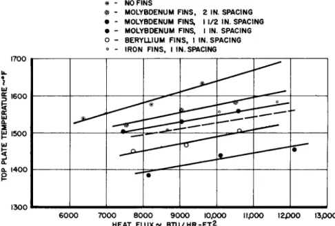
The test results are presented in Fig. 2, which shows the top plate temperature measured at the time when 50$ of the hydride was melted vs the heat flux. It can be observed that the heated surface temperatures for plates without fins are higher than those for plates with fins. Furthermore, the densest fin spacings transfer the most heat, and, for a given fin spacing, the fin material with the highest thermal conduc- tivity transfers the most heat. All of these results are compatible with the previously known theory. The most import- ant single result is the fact that a flux of 10,000 Btu/hr ft2 is possible without fins with an indicated surface tem- perature of l650°F.
Table 1 Fin materials employed Material
Beryllium Graphite Molybdenum
Electrolytic iron
Ratio of specific weight to Thermal conductivity
2 Л 2 lb/ft3/Bbu/Hr-ft - UF 4.05
9.7^
24.0
Heat Release Investigation
Lithium hydride heat release is affected by the geometry of the boiler tubes and the behavior of the boiling working fluid.
Hence, it becomes quite complicated to evaluate all of the factors analytically. Both a direct experimental model and an electrical analog were employed to measure the heat release performance. In the former, the effect of zero gravity cannot be simulated since the configuration requires two-dimensional rather than one-dimensional heat transfer. However, convec- tion was minimized by orienting the short dimension of the bath vertically.
The thermal resistance of lithium hydride freezing around a tube immersed in an actual storage bath differs from the thermal resistance of a tube immersed in an infinite bath because of the interference of the container walls and of hy- dride freezing around adjacent tubes and fins, if present.
An electric analog was conceived and adapted to the freezing problem to determine the motion of the melt line with time.
This application of an electric analog is believed to be novel in this field of heat transfer and consequently is the subject of a forthcoming paper. Only a short synopsis of the theory and the results are presented here.
In the general case of solid material around a tube from which heat is being removed, it can be demonstrated that from an isotherm in the solid a series of local areas can be defined through which the heat flows from the melt line are equal.
As the freezing process continues, the melt line will move to a new position determined by the local heat flows. The amount of heat transferred during that time interval is equal to the amount of material frozen. Thus,
in which ^Л *Р^&пДп
f* = the time interval, min tyrt = local heat flow, Btu/min
p = material specific weight, lb/ft3 Д = material heat of fusion, Btu/lb
<Jl = local distance between isotherm and melt line at the beginning of the time interval, /[to = local distance between the melt line at the ft beginning of the time interval and the melt line at the end of the time interval, ft A third dimension is necessary on the right-hand side of the foregoing equation. It is the unit distance along the tube. Since the local heat flows are all equal, the ratio
'$>l/PA> i s a constant for all the local areas. Hence, the values of £fy /\^j all are equal, and the new position of the melt line is inversely proportional to the local distance between the melt line and the isotherm in the solid. With this principle, it is possible to trace the movement of the melt line from the tube to the point where all the material is frozen. A typical unit in the electric analog is shown in Fig. 3.
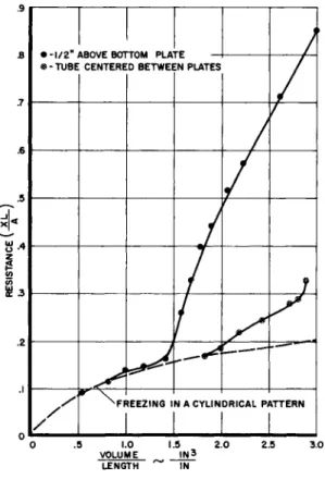
At each position of the melt line, the electrical resis- tance between the melt line and the tube was measured and the amount of hydride frozen determined by a planimeter measure- ment of the area bounded by the tube wall, the melt line, and the bottom plate. The measured electrical resistance was con- verted to a geometrical resistance parameter by dividing the electrical resistance by the unit electrical resistance of a square of the conducting paper. The analogous thermal resis- tance is calculated by dividing the geometrical resistance parameter by the thermal conductivity. Two geometries were investigated, one in which the tube was centered between the two walls and the other in which the tube center was \/h of the distance from one of the walls. In both cases, the tube spacing was that contemplated for the Sunflower boiler heat storage unit.
Fig. h illustrates the analog results obtained. The re- sistance for a tube immersed in an infinite bath is shown for comparison with the two geometries. A slight wall interference can be observed for the off-center tube, but the influence of the hydride frozen around the adjacent tube is much more pro- nounced. The resistance rises rapidly after the convergence of the two melt lines. In the case of the centered tube, the resistance follows the infinite bath variation until the two melt lines meet, after which the resistance rises, but not as rapidly as that for the off-center tube.
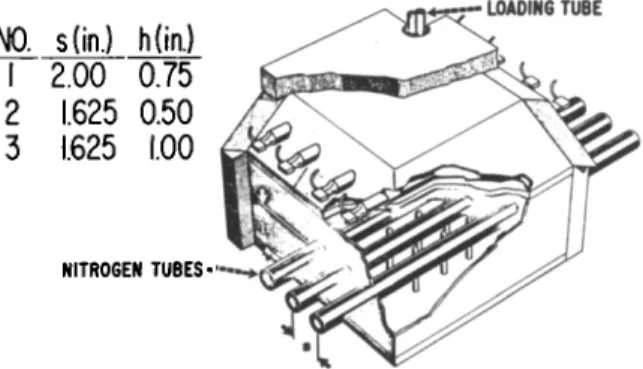
Experimental confirmation of the analog results was nec- essary to establish their validity. Test modules were cons- tructed with the two geometries and loaded with hydride. Fig.
5 is a drawing of the test assembly employed. Nitrogen gas was the coolant, and again heat was applied to the top plate.
Temperatures measured included nitrogen inlet and outlet, tube wall, top plate and several hydride positions. Heater input and nitrogen flow also were measured.
Figure 6 presents the results obtained for the off-center tube for tests conducted in both the horizontal and vertical test positions. The horizontal position minimizes the effects
of natural convection. It can be observed that in this test position the agreement between the experimental and the analog results is reasonably good. The test results in the vertical position indicate the strong influence of natural convection
and emphasize the need to minimize it if the results are to be applied to low gravity operation. Similar results were
obtained for the other geometries tested.
Another important characteristic of lithium hydride is the dissociation pressure which is discussed below.
Dissociation Pressure
The gas released by liquid hydride is hydrogen, of course.
The hydrogen dissociation pressure is a function of the liquid temperature, as shown in Fig. 7- It can be observed from Fig.
7 that the dissociation pressure increases rapidly with tem- perature. The dissociation pressure is also a function of the percentage of lithium hydride present in the mixture of lithium and lithium hydride. The dissociation pressure reaches its maximum value at 100$ lithium hydride. As the percentage of lithium hydride is reduced, the dissociation pressure de-
creases to a plateau value that is temperature dependent only.
The dissociation pressure shown in Fig. 7 is the plateau pressure at each temperature. The range of percentage of lith- ium hydride over which the dissociation pressure is constant at the plateau value decreases with increasing temperature.
Space applications such as Sunflower require minimum system weight that can be obtained by limiting the operating pressure level, as will be discussed later. The dissociation pressure and its variation with temperature are factors that must be considered in system design.
The hydrogen vapor is free to diffuse through the walls of the container and the boiler. The hydrogen thus lost can reduce quickly the bath storage capacity. Therefore, an ex- perimental program is in progress to determine materials and/
or coatings capable of containing hydrogen within acceptable limits for a year's operation in orbit. At present, the glass coatings appear the most promising.
Compatibility with Containment Materials
To obtain minimum weight, it is necessary to design the storage bath container wall to a minimum thickness consistent with containing the lithium hydride at pressure and tempera- ture for one year. The dissociation pressure and hydrogen diffusion already have been mentioned as design criteria.
Another important factor that must be considered is possib- ility of material attack caused by corrosion.
Experimental investigations have been conducted to deter- mine the seriousness of the attack under the conditions of the Sunflower system being developed. The reduction in wall thickness for suitable test times has been determined, and the data extrapolated to estimate the reduction per year.
In tests of up to 3OOO hours duration, a number of mater- ials have indicated an extrapolated compatibility sufficient to limit penetration to 5 mils or less per year. Examples include Type 3^7 stainless steel and Haynes Alloy #25»
Hydride Loading
Three forms of lithium hydride were considered for the Sun- flower application, powdered, lump, and internally generated.
The powdered form must be vibrated on loading to achieve reas- onable percentages of theoretical density, and the powder can include small amounts of lithium hydroxide, which is undesir- able. The lump form must be melted again on loading and must be protected during long term storage. The equipment needed to load a complex storage unit with lithium hydride by either of these two methods was considered to be as extensive as the equipment needed for internal on-site generation. The last method has the advantage of minimum storage and should result
in maximum purity.
The hydride loading technique must be consistent with main- tenance of purity and control of quantity within the storage volume. For these reasons the technique that has been selected for the Sunflower unit employs integration of the hydride
reaction and filling operations. Specifically, a fixture was provided which permitted hermetic attachment of a reactor vessel to the heat storage unit. Lithium ingot and hydrogen gas are reacted in the external vessel and, upon completion of the reaction, the hydride immediately is transferred to the unit. This method requires all metal parts exposed to the hydride to be at a temperature equal to or greater than the freezing temperature, 1270°F, to prevent uncontrolled freezing of the hydride with resultant plugging of the transfer lines and incomplete loading of the storage unit.
This technique has been employed to fill two preprototype boilers with notable freedom from difficulty in the process
or the result. Each of the two storage units contained over 1^0 lb of lithium hydride.
Development Unit Design
It was required that the size and shape of the lithium hy- dride storage container for the development unit be as similar as possible to the flightweight version. For reasons of safety and ease of fabrication; wall thickness of l/k in, was specified. Since the austenitic stainless steels had been shown to be sufficiently compatible with lithium hydride, AISI 316L was selected as the material for the initial units.
Review of the optics of the cavity receiver indicated the desirability of separating the geometrical center from the collector focal point (center of the aperture).
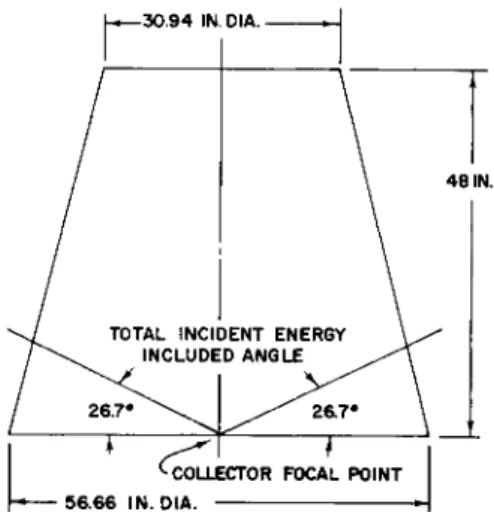
The shape of the hydride container was influenced by the incident energy pattern provided by the annular solar collector and the Sunflower envelope specifications.
These limitations are shown graphically in Fig. 8. The results of optimization studies indicated that the minimum nominal hydride thickness was 2 in. and that the shape of the container should be a hemisphere or a segment of a sphere.
The latter result is not surprising, since it is well known that the principal stresses are minimized in a sphere, which permits minimum wall thickness. The hydride thickness specif-
ication arises from the volume of hydride required in the flight container and the maximum practical heat absorption surface area that can fit within the envelope and be exposed to the incident energy. The hydride thickness was set at 2 in.
arid a hemispherical annular container was designed for the development units. A straight flange was added to the hemi- sphere, and a heavy ring closed the two shells. The mean radius in the hydride was set at the value intended for the flightweight unit. A sketch of the development container is presented in Fig. 9*
Test Results
Tests have been conducted on two development units to date.
The tests were intended to determine the percentage of heat storage potential that can be utilized in an actual system.
The hydride bath was stabilized at a known uniform temperature.
Simultaneously, the bath heater was turned off and the mercury flow started and maintained as constant as possible until the boiler outlet temperature dropped to the saturation level.
Mercury flow was then stopped and the time recorded. Two initial bath temperature levels, 1350°F and 1500°F, were employed.
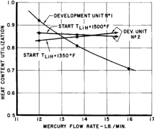
The useful heat extracted is the product of the mercury flow rate and the mercury enthalpy change and the time. Addi- tional heat is lost through the container walls to the sur- roundings. The heat available is the product of the weight of lithium hydride and the hydride enthalpy changes. The final enthalpy level of the hydride is based on a temperature calculated as the average of 21 immersed thermocouple readings.
The utilization efficiency is defined as the ratio of the use- ful heat extracted to the heat available. The results are presented in Fig. 10 as the utilization efficiency vs the mercury flow rate.
It can be observed that, in the first unit, the efficiency decreased as the mercury flow rate increased. On the other hand, the efficiency in the second unit appeared to be essen- tially independent of mercury flow rate and remained essen- tially constant at about 85$. The difference in operating results of the two units is attributed to the different hydride bath temperature distributions encountered because of a change in attitude of the two units. The first unit was heated from above and indicated a gradient of about ^00°F within the hy- dride bath at steady state. The second unit was heated from below and demonstrated essentially uniform temperatures at steady state. The lack of any measurable gradient within the hydride bath was the most noticeable characteristic of the
second unit. The uniform temperature distributions of the second unit provide greater efficiencies at the higher flow rates.
Conclusions
Based on the results of the work described in this paper, the following conclusions may be drawn:
1) The feasibility of lithium hydride as a heat storage material in space power conversion systems has been demon-
strated in full-scale hardware.
2) Ground tests conducted on two full-scale storage units indicated that about 85$ of the available lithium hydride enthalpy change, or as much as l6l0 Btu/lb., can be trans- ferred to the Sunflower mercury working fluid during shade time operation.
Bibliography
Rudy, J. A«. and Picking, J. \1.9 "Sunflower thermodynamic power system development status" (published elsewhere in this volume)»
FIN s(in.)
< LOADING TUBE
Mo Mo Mo Fe Be
1.5 1.2 1.0 1.0 1.0
P T " I \ I
I
!^
<**
NITROGEN
•&Ч
NITROGEN
Fig. 1 Lithium hydride heat input test assembly
1700
ш | 1600
<
a: Hi
a. £ 1500 ш
ü
Q.
o. 1400
1300
® - NO FINS
® - MOLYBDENUM FINS, 2 IN. SPACING
• - MOLYBDENUM FINS, I 1/2 IN. SPACING
• - MOLYBDENUM FINS, I IN. SPACING O - BERYLLIUM FINS, I IN. SPACING
® - IRON FINS, I IN. SPACING
*®
•
i——""^^
g> —
•
6000 7000 8000 9000 10,000 11,000 12000 13,000 HEAT FUUX~ BTU/HR-FT2
Fig. 2 Top plate temperature variation with heat flux at time when 50$ of lithium hydride is melted
-INNER WALL OUTER WALL
EQUIPOTENTIAL
LINE BOILER TUBE
MELT LINE POSITION 5
Fig. 3 Electric analog for lithium hydride freezing around a tube in a storage bath
LENGTH
Fig. h Analog predictions of geometrical resistance variation with volume of lithium hydride frozen
N0. s(in-) h(in.) 1 2.00 0.75 2 1.625 0.50 3 1.625 1.00
NITROGEN TUBES-
, < - . - - - LOADING TUBE
Fig. 5 Lithium hydride heat release test assembly
MODULE N0.2
c-tr
\^'-
•*•**■*
HORI
ANALOG .
/V //
£'
ZONTAL T
-^ / « / /
I I / I I l 1 I 1 i 1 I 1 t 1 i
/ / r /
/ / / / /
if i / if
// fi
\ i
/
^VERTICA
/ / / / / /
LTEST
1.0 1.5 2.0 2.5 3.0 IN3/IN
6 Comparison of analog and experimental variations of geometrical resistance with volume of lithium hydride frozen
800
Z 600 2
§ 400
1 \
1 ATMOSPHERE
1100 1300 1500
TEMPERATURE (eF)
1700
Fig. 7 Plateau dissociation pressures lithium-lithium hydride system
48 IN.
1 ~Z^\ Г
^COLLECTOR FOCAL POINT
•56.66 IN. DIA.
Fig. 8 Allowable boiler heat storage unit space envelope and collected energy boundary in Sunflower I system
SPACE ENVELOPE
-COLLECTOR FOCAL POINT
Fig. 9 Lithium hydride container configuration in development unit No. 1
i.o
0.9 o i-
<
0.8
0.7
0.6
0 5 .
\
1
START
^-DEVELOPMENT UNITf
<У i i
r3
TLiH-13
IAKI I Lj H" 1500-
50°F
Jel
^^C^DEV. UNIT
~v
№2II 12 13 14 15 16 17 MERCURY FLOW RATE-LB./MIN.
Fig. 10 Variation of heat content utilization with mercury flow rate in development units 1 and 2