A Method for Determining Roundness and Actual Form of Circular Workpiece Cross Sections
Imre Némedi
1, Milenko Sekulić
2, Vladan Radlovački
2, Janko Hodolič
2, Miodrag Hadžistević
2, Márta Takács
3,41Subotica Tech - College of Applied Sciences, Marka Oreškovića 16, 24000 Subotica, Serbia, E-mail: nimre@vts.su.ac.rs
2 University of Novi Sad, Faculty of Technical Sciences, Trg Dositeja Obradovića 6, 21000 Novi Sad, Serbia, E-mail: milenkos@uns.ac.rs, rule@uns.ac.rs,
hodolic@uns.ac.rs, miodrags@uns.ac.rs
3 Óbuda University, Bécsi út 96/b, H-1034 Budapest, Hungary, E-mail:
takacs.marta@nik.uni-obuda.hu
4 University of Novi Sad, Hungarian Language Teacher Training Faculty, Subotica, Stromajerova 11, Serbia, E-mail: takacs.marta@magister.uns.ac.rs
Abstract: Determining a roundness value is essential for enabling fast, easy and smooth assembly of workpieces with circular fitting surfaces. In a number of cases, roundness specifications should be defined if other geometrical specifications are not sufficient for enabling reliable assembly. Various standards treat roundness as a deviation from an ideal circle, whereas, the actual cross section form is not treated at all. It seems this characteristic is not worth examining. Knowing the cross section form, however, enables determining various factors that result in undesirable deviations of workpiece cross sections from an ideal circle. This paper presents a new method which, in addition to determining roundness, can be used to determine the actual form of a circular workpiece cross section, using a coordinate measuring machine.
Keywords: Cross section actual form; roundness; CMM; V-block method
1 Introduction
This paper presents a new method for determining the actual form of a circular workpiece cross section and determining roundness. By knowing the actual form of a cross section, some important information for detecting production errors may
become clear much before they cause unnecessary wastes and costs. To the knowledge of the authors, no method has yet been proposed to solve problems of determining the actual form of a cross section and roundness at the same time.
This method may be of a great help in a process where timely detecting form errors of workpieces with circular cross sections is needed. The method is based on analyzing so called "Core of centers", a set of points obtained by calculations described in further text.
Roundness is observed on the basis of internationally accepted and applicable parameters of roundness and specification operators [1]. In their study, Shunmugam and Venkaiah report the results of comparing different methods for processing the results of measuring roundness and cylindricity, and the review thereof [2, 3, 4].
Roundness can be measured in several ways, using different methods. They range from simple diameter measurement and measurement in prism (V-block method) [5, 6], then measuring using computer controlled Coordinate Measuring Machines (CMM), to using special equipment for measuring roundness, which operates on the basis of the Rotational Datum Method (RDM).
These methods are constantly being revised with the aim of improving measurement accuracy [5, 7]. It should be noted that efforts are made to improve conventional methods as well, such as V-block method, which is widely accepted for measuring roundness. However, significant problems exist in analyzing results. These problems are being solved by using inverse matrices [7]. Thus, data processing is being developed, but the measurement principle remains the same, with all its drawbacks [8, 9, 10, 11]. These drawbacks are an integral part of a measurement process. In the V-block method they include permanent movement of the rotation center during the rotation of the measured object along a leaning surface.
2 Description
2.1 Roundness
Roundness tolerance zone in a plane is limited by two concentric circles at a distance t [12].
Roundness can be defined in four ways [13, 14]. In this paper, the definition of roundness using Circular zone with minimum radial separation (Minimum Zone Circles, MZC) is applied.
2.2 Actual Form of a Cross Section
Actual form of circular work pieces deviates from the ideal one. These deviations depend on a number of factors, primarily on the rigidity of a work piece material and machine components, as well as on clamping. Actual forms of circular work pieces' cross sections (both the shaft and holes) most often appear as: a) triangular or polygonal, b) oval or c) multiangular.
Common methods used to determine roundness do not generally enable determining any type of actual form of a circular work piece cross section.
Assuming the most probable actual form is usually needed before the measurement. This requires considerable experience. Using CMM easily provides roundness values, but actual form of a cross section still usually remains unknown.
For example, a triangular actual form is common with thin-walled pipes if the clamping is made at three points.
3 Core of Centers Method
Common measuring methods used with ring-shaped cross sections and some other workpieces, require gauges that establish contacts with the measured surface at three points. These are workpieces with triangular and pentagonal cross section error forms. However, oval and square error forms cannot be determined with the required accuracy using three-point contacts. With such shapes contact needs to be made at two points. The most important problem when measuring roundness using common methods is the unknown position of the center and the axis of the measured cross section.
If we want to uncover the form of roundness error (or the actual form of a workpiece cross section), it is necessary to follow positions of those centers. The core of centers method was named after the positions of these centers which it thoroughly analyzes.
The method assumes the use of a coordinate measuring machine. The first step of the method is collecting the coordinates of all cross section contour points using the standard probe.
The easiest way to present and explain the method is by providing examples of ideal oval and pentagonal cross section error forms, using graph presentations.
The second step is calculating the centers of circumscribed auxiliary circles, drawn on pairs or triplets of points from the contour.
Preliminary empirical evidence tells us that data from oval, square and other cross sections with an even number of vertices should be calculated using three-point calculations, while data from other cross sections (triangular, pentagonal etc.) should be subject to two-point calculations, which is actually opposite to the common methods. The reason is obvious: uncovering the positions of the auxiliary circles' centers makes the method. Triplets are contour points on the lines drawn from the center, making angles of 120° each, while the two-points calculation is based on selecting opposite points of the contour.
A scheme of three-point data calculations of the actual, oval contour is presented in Figure 1.
An auxiliary circle is constructed using the selected contour points. The center of this circle is easy to determine.
Figure 1
A circle defined by three selected points with its center
After a rotation for a desired angle, the procedure is repeated: another auxiliary circle is obtained along with its center. This step is presented in Figure 2.
Figure 2
Two auxiliary circles with their centers
The described step is repeated for n times until the contour is entirely rounded.
The centers of the auxiliary circles are distributed according to a certain pattern.
This pattern actually presents the "path" of the cross section center "movement"
during the rotation and the calculation. The set of centers (core of centers) indicates a roundness error form of the cross section.
At the same time, empirical evidence shows that the "core of centers" points to an actual form of a work piece cross section. Thus, the form of the core of centers is obtained using the "movement" of auxiliary circle centers. If the calculations had been done using pairs of points, the auxiliary circles would have been nearly concentric, and their centers would have coincided providing an unusable image.
All types of roundness error forms can be analyzed using the described method, e.g. ideal pentagonal form presented in Figure 3.
Figure 3
The results of two-point data calculations around the entire contour on the pentagonal error form
Appropriate magnification provides clarity - Figure 4 shows an enlarged core of centers.
Figure 4
An enlarged core for the pentagonal error form as a result of two-point calculations
Unlike the oval error form, in the case of the pentagonal error form, two-points data calculations must be used. Two points used for drawing auxiliary circles are located on the opposite sides of a cross section contour. The result obtained undoubtedly points to the pentagonal error form.
Calculations using triplets of points result in an unusable distribution of centers - they are scattered along the core of centers, see Figure 5.
Figure 5
An enlarged picture of a core for pentagonal deviation with three-point calculations
The obtained results show that choosing the number of points for calculation depends on the number of sides of the roundness error form. For an even number of sides of the form (including oval form) three points should be used, while an odd number of sides (vertices) requires the use of pairs of points.
Practical measurements imply that the error form type is not known in advance.
To determine the form and enable further processing, calculations need to be performed with both two and three calculation points, and, based on the obtained shape of the core of centers, an unambiguous conclusion should be made about the actual form of the measured object's cross section.
Determining roundness is explained later as a part of experiment.
4 Experiment, Results and Discussion
4.1 Measurement and Workpieces Used
The measurements were performed in the Metrological laboratory at the Department of Metrology, quality, equipment, tools and ecological engineering aspects at the Faculty of Technical Sciences in Novi Sad. The coordinate measuring machine Carl Zeiss CONTURA G2 was used to complete the measurements. Measurement uncertainty of these machine is MPEE=1.9 m.
The measurement conditions were standard – working environment temperature was 21C and humidity was within the standard limits (40 – 60%).
Work pieces were also measured in Mitutoyo Hungaria Kft Testing Laboratory in Budapest, using a special measuring machine for determining roundness, Ra-2100 (RDM), width mmeasurement uncertainty MPEE=0.02 m!
Environmental conditions in the laboratory were within required limits (t=21.2C, humidity was 46%).
For the provision of comparable methodological background with the CMM measurements, the MZC method without filtering was selected.
Work pieces used for the measurements were cylinder d=17.2 mm, and thin- walled pipe d= mm (Fig. 6).
Figure 6 presents work pieces used for measurement - measuring surfaces are marked with arrows.
a) b) Figure 6
The measured workpieces – a) master cylinder d=17.2 mm, and b) thin-walled pipe d=30mm
4.2 Data Processing
In Section 3, for the purpose of providing appropriate explanations, cross-section center was assumed fixed. The situation with the actual work pieces is significantly different. There is no rotation center point defined in advance, it yet needs to be determined. The rotation center corresponds to the so-called Best Fit circle. Many researchers use a well-known Least Square method for its determination. However, Maisonobe had a different approach [15]. To find the center he used the bisectors' intersections of paired line segments which connect randomly selected triplets from the set of measuring points.
Now, by selecting triplets from the set of the measured points adequate circles are determined. Their centers have to be calculated.
The equations of bisectors of adjacent line segments Pi(xi;yi) ÷ Pj(xj;yj) and Pj(xj;yj) ÷ Pk(xk;yk) are given by formulas 1 to 4: In Section 3, for the purpose of providing appropriate explanations, cross-section center was assumed fixed. The situation with the actual work pieces is significantly different. There is no rotation center point defined in advance, it yet needs to be determined. The rotation center corresponds to the so-called Best Fit circle. Many researchers use a well-known Least Square method for its determination. However, Maisonobe had a different approach [15]. To find the center he used the bisectors' intersections of paired line
segments which connect randomly selected triplets from the set of measuring points.
Now, by selecting triplets from the set of the measured points adequate circles are determined. Their centers have to be calculated.
The equations of bisectors of adjacent line segments Pi(xi;yi) ÷ Pj(xj;yj) and Pj(xj;yj) ÷ Pk(xk;yk) are given by formulas 1 to 4:
2 i) j y y j( , ) i xj xi ( k , j , ci x
(1)
2
i) j x x j( , ) i yj yi ( k , j , ci
y
(2)
2
j) k y y k( , ) j xk xj ( k , j , ci
x
(3)
2
j) k x x k( , ) j yk yj ( k , j , ci
y
(4) Solving this system of linear equations results in (expressions 5-7):
( )( ) ( )( )
,
yj yk yi yk xj xk xi xk j
i (5)
( )( ) ( )( )
,
yi yj yi yk xi xj xi xk k
j (6)
where:
) )(
( ) )(
(xk xj yj yi xj xi yk yj
(7)
The coordinates of the circle center expressed as a function of the selected three coordinates are then (8 and 9):
2
) 2 2 )(
( ) 2 2 )(
( ) 2 2 )(
( , ,
yk xk yi yj yj xj yk yi yi xi yj yk k j ci
x (8)
2
2) )( 2 ( 2) )( 2 ( 2) )( 2 (
, ,
yk xk xi xj yj xj xk xi yi xi xj xk k j ci
y (9)
This procedure has to be repeated using all possible triplets from the contour.
Using the described algorithm, Maisonobe obtained a cloud of intersection points.
This is followed by finding the focus point within this cloud. For that purpose Maisonobe used a special type of iterations [15]. The result of these iterations is the position of the Best Fit circle center. Based on the nature of this method, this point was named a triangular center.
After the triangular center is known, the core of centers is determined by selecting pairs or triplets of contour points and carrying out calculations as explained earlier. The number of calculations needed here is significantly smaller. Cases where pairs of points were used are referred to in the following text as two-point calculations, while triplets of points are referred to three-point calculations.
4.2 Results of Measurements and Measured Data Processing
Results for master cylinder d=17.2 mm
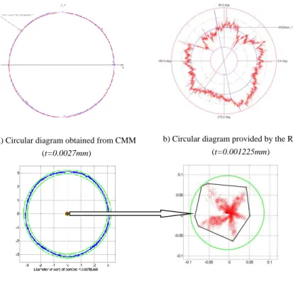
Provided review of results includes CMM reports with n=1600 measuring points along with measured roundness values (t). This is followed by results of measuring roundness using RDM and Roundtest Ra-2100 special measuring machine, with roundness value determined on the basis of n=7200 measuring contour points (the machine had this number of points as a minimum). Next is a review of results of measured points coordinates processing by using the method proposed in this study. Circular diagrams are given, together with enlarged core centers. Circular diagrams are very similar to these obtained directly from the CMM. As previously emphasized, cores are different depending on whether two or three-point calculations were used. For the purpose of comparison, both cases are presented (see Fig. 7).
Under circular diagrams obtained by the proposed method, values t as diameters of cores of centers are also designated. These values are determined using the core of centers method. Namely, by drawing a circle as an envelope around the core of centers with the triangular center and by determining its diameter (see enlarged cores and Figure 7c and 7d), values very close to CMM determined roundness error values are obtained. By analyzing several workpieces of the same type (these analyses are not presented herein for understandable reasons), described method is found very useful for estimating roundness error. Envelope circle is determined by a triangular center and the position of the furthest point in the core (these two points make the radius of an envelope circle).
a) Circular diagram obtained from CMM (t=0.0027mm)
b) Circular diagram provided by the RDM (t=0.001225mm)
c) Core of centers results with two-points calculations (t=0.0018268mm)
d) Core of centers results with three-points calculations (t=0.0020948mm) Figure 7
Measuring results for cylinder d=17.2 mm
Figure 7 makes obvious the difference between results of two and three-point calculations. All important values are shown separately, under the figures. The actual form of a cross-section is impossible to determine by observing only CMM or core of centers circular diagrams (Figures 7a, 7c and 7d). Special Roundtest machine provides circular diagram which shows the real form of a cross section.
However, core of centers shape from Figure 7c unambiguously points out to a pentagonal cross section error form (also see Figure 3). This core is obtained using two-point calculations. On the other hand, if three-point calculations are used (see Fig. 7d), a core of centers is shaped as a cloud of points which, at the best, makes determining the real cross section form impossible. So, for pentagonal cross section error forms, two points calculations should be used, as previously explained.
Differences between CMM (t=0.0027 mm) and RDM (t=0.001225 mm) results are expected. Namely, measured cross sections for these two measurements cannot be identical. During the measurement, all possible measures were undertaken to prevent measuring different cross-sections. There also exists a difference between numbers of measuring contour points as previously explained. This cannot imply extreme result differences, but also can have significant impact to evaluating roundness error. On the other hand, it appeared that core of centers method provided better evaluation of roundness error (t=0.0018268 mm) then the CMM, based on same set of contour point coordinates (see Table 1).
Table 1
Estimates of roundness errors t for cylinder d=17.2 mm (values in mm)
CMM Core of centers method RDM
0.0027 0.0018268 0.001225
Results for thin-walled pipe d=30 mm
Second example is a thin-walled pipe deformed for unknown reasons to the squared roundness deviation. Deformation is even visible from circular diagrams (see Fig. 8). This example also points out to the practical usability of a proposed method.
Determining real form of a cross-section does not require using core of centers method in this case. Core of centers from Fig. 8c is obtained using two-point calculations, while three-point calculations produce core of centers given in Fig.
8d. By analyzing several workpieces of the same type (these analyses are also not presented herein) it is proven that the core shape from Fig. 8c is impossible to obtain in any other way. It shows that using two-point calculations is not to be used in this case. So, using three-point calculations is the only remaining alternative.
a) Circular diagram obtained from CMM (t=0.0732mm)
b) Circular diagram provided by the RDM (t=0.08628mm)
c) Core of centers results with two-points calculations (t=0.032325mm)
d) Core of centers results with three-points calculations (t=0.073505mm) Figure 8
Measuring results for thin-walled pipe d=30 mm Table 2
Estimates of roundness errors t for thin-walled pipe d=30 mm(values in mm)
CMM Core of centers method RDM
0.0732 0.073505 0.08628
Results are very similar to the ones in the previous case. The RDM roundness estimate is again different from the estimate provided by CMM, while core of centers method estimate is close to CMM estimate, yet between the rest two values.
In case of larger scale deviation, as the results prove it, the Core of Centers Method does not provide greater accuracy of the roundness value. Knowing that the CMM and the Core of Centers Method works with the same entering data, the only acceptable explanation is that the mathematical apparatus in such cases produces similar results. The reason of this may be found in the detailed mathematical analysis of both methods which could be an interesting theme of a new research. In any case the aim of the real form of the part’s cross section did not fail to be attained either.
Based on described results of measurement and measured points coordinates processing results, the following conclusions can be drawn:
1. Core of centers method provides an unambiguous and reliable estimate of a rotating workpiece's measured cross-section's real form, regardless of a roundness error value. For small and even for large deviations from the ideal circle, the method is stable and always provides useful results.
2. Completed measurements showed that the number of points to be used in calculations for determining auxiliary circles in core of centers method has to be carefully determined. If an expected cross-section real form is a polygon with even number of sides (vertices), 3 points should be used for calculations. For an odd number of expected polygon sides, 2 points calculations should be used.
This reasoning reminds us of the processing of polygonal holes by means of a special drilling tool. This time the number of necessary cutting edges if the number is odd (ex. 3, 5, etc.) will be 2 (two), but if the number is even (ex. 4, 6, etc.) will be 3 (three). Everything else is achieved by the complex moving of the axis of the drilling tool.
So the logical conclusion is the same, only the application is reversed.
Instead of the number of cutting edges the number of measuring points (2 or 3 points calculations) comes into consideration,, while the moving of the tool’s axis is done by the position of the centers of auxiliary circles.
The practical application of the method as it is imagined can be represented by thought of 7c and d as well as 8c and d figures. A set of coordinates of the measuring points, that we got from the CMM is processing by 2 and 3 point touch (method with 2 or 3 points calculations). On basis of the cores that we got in this way we can have an unambiguous decision on the real form.
3. Core of centers obtained by applying the method can be used not only for determining a real form of a circular workpiece cross-section, but for estimating a roundness error as well. The diameter of a core envelope circle can be used for that purpose. There are indications that in cases of small deviations from ideal circle (i.e. small roundness error values) this method results are more accurate then methods used in modern CMMs.
Conclusions
Inspecting workpiece form errors, during production is often a key, to achieving smooth and fast assembly. Inspecting form errors is very important when narrow tolerances exist. In such cases real forms of fitting surfaces have significant impact on a likelihood of successful and effective assembly of paired workpieces.
On the other hand, by recognizing the actual form of a cross-section may help revealing systematic and random external effects implying unfavorable variations.
This information can be used as a guideline for committing appropriate adjustments and corrective actions to the production system, i.e. reducing or eliminating any unfavorable external effects.
The results of this study support the significant practical value of the proposed method. However, these results can also be treated as preliminary, for more extensive research is required to improve the method and bring it into practical use. It is authors' opinion that using this method, that reveals both the roundness error and actual form of a workpiece cross-section, may contribute a great deal to increasing the efficiency of some measuring and inspection processes. Its application might help revealing causes of the nonconformities that emerge during production, management of assembly process and therefore, decrease production costs, by providing important information about nonconformity causes in real time.
References
[1] International Organization for Standardization, Geneva, Switzerland, ISO/TS 12181–1 and 12181–2, Geometrical product specifications (GPS) – Roundness; Part 1: Terms, definitions and parameters of roundness and Part 2: Specification operators, international standards, 2003
[2] M. S. Shunmugam, N. Venkaiah: Establishing circle and circular-cylinder references using computational geometric techniques, Int J Adv Manuf Technol 51 (1-4), 2010, pp. 261-275
[3] M. S. Shunmugam, N. Venkaiah: Evaluation of form data using computational geometric techniques—Part I: Circularity error, Int J Mach Tool Manu 47 (7-8), 2007, pp. 1229-1236
[4] N. Venkaiah, M. S. Shunmugam: Evaluation of form data using computational geometric techniques—Part II: Cylindricity error, Int J Mach Tool Manu 47 (7-8), 2007, pp. 1237-1245
[5] S. Adamczak, D. Janecki, K. Stepien: Cylindricity measurement by the V–
block method – Theoretical and practical problems, Measurement 44 (1), 2011, pp. 164-173
[6] K. Stepien, D. Janecki, S. Adamczak: Investigating the influence of selected factors on results of V–block cylindricity measurements, Measurement, 44 (4), 2011, pp. 767-777
[7] E. Okuyama, K. Goho, K. Mitsui: New analytical method for V–block three–point method, Precis Eng 27 (3), 2003, pp. 234-244
[8] J. Gi–Bum, H. K. Dong, Y. J. Dong: Real time monitoring and diagnosis system development in turning through measuring a roundness error based on three–point method, Int J Mach Tool Manu, 45 (12-13), 2005, pp. 1494- 1503
[9] G. Wei, K. Satoshi, S. Takamitu: High–accuracy roundness measurement by a new error separation method, Precis Eng 21 (2-3), 1997, pp. 123-133 [10] G. X. Zhang: A Study on the Abbe Principle and Abbe Error, CIRP Ann-
Manuf Techn 38 (1), 1989, pp. 525-528
[11] R. Thalmann: Basics of highest accuracy roundness measurement, Simposio de Metrologia 2006 of CENAM (Centro Nacional de Metrología), Queretaro, Mexico, 2006, pp. 1-6
[12] International Organization for Standardization, Geneva, Switzerland, ISO 1101, Geometrical product specifications (GPS) - Geometrical tolerancing - Tolerances of form, orientation, location and run-out, 2012
[13] R.W. Berger: The Certified Quality Engineer Handbook, ASQ Quality Press, 2007, pp. 253-255
[14] M. Hadžistević, I. Nemedi, M. Sekulić, M. Bosak, J. Hodolič: Multi–
Aspect Value of Measuring Systems and Methods Based on the Results of Roundness Measurements, Journal of Mechanics Engineering and Automation 2 (8), 2012, pp. 514-530
[15] L. Maisonobe (2007) Finding the circle that best fits a set of points,
<http://www.spaceroots.org/documents/circle/circle-fitting.pdf /> (accessed 12 Mar 2012)