Adhesion and sliding tribological properties of polyolefins treated by diffuse coplanar surface barrier discharges
Ádám Sarankó a, Zoltán Szakál a, Gabor Kalacska a, Pieter Samyn b, Jacob Sukumaran c, Szilvia Klébert d, Zoltán Károly d*
a Institute for Mechanical Engineering Technology, Szent István University, Páter Károly u.1, H-2100 Gödöllő, Hungary
b Applied and Analytical Chemistry, Institute for Materials Research (IMO-IMOMEC), Hasselt University, Agoralaan Gebouw D, B-3590 Diepenbeek, Belgium,
c Department of Mechanical Construction and Production, University of Ghent, Belgium,
d Institute of Materials and Environmental Chemistry, Research Centre for Natural Sciences Hungarian Academy of Sciences, Magyar tudósok krt. 2., H-1117, Budapest, Hungary
*Corresponding author: karoly.zoltan@ttk.mta.hu, tel. +36 1 3826504
Abstract
A study is presented on the plasma treatment of two different ultra-high molecular weight polyethylene (UHMWPE) and polypropylene (PP) surfaces by using diffuse coplanar surface barrier discharges under atmospheric air conditions. The plasma-treated polymer surfaces are characterized in terms of wettability, surface chemistry, topography, adhesion and tribology.
It is found that plasma treatment significantly improves wettability through formation of various oxygen containing functionalities at the surface. The plasma treatment consequently improves adhesion for either polymer/polymer or polymer/steel joints. Under dry sliding conditions the coefficient of friction slightly increases after plasma treatment in parallel with the higher adhesion. In contrast, the coefficient of friction significantly decreases under oil lubrication conditions and it remains low even after cleaning the oil likely due to the improved oil retention capability of the plasma-treated surface. The observed tendencies in adhesion and friction are further analyzed in terms of surface chemistry after plasma treatment and after sliding by use of spectroscopic methods and chemical imaging.
Keywords: cold plasma; DCSBD; adhesion; friction; polyolefins
1 Introduction
Polymers are frequently used for constructional engineering applications due to their favorable properties like machinability, dimensional stability, resistance to corrosion, most solvents and acids combined with low cost. In many design cases, the polymers are joined with other materials of similar or distinct types by some adhesive and/or used in direct contact with moving parts. Therefore, the control over physical and chemical surface properties is of paramount importance in terms of wettability, adhesion or friction. As these properties are inherently poor for polyolefins [1-2], in part due to the lack of polar chemical groups, their improvement was the goal of lots of earlier researches [3-7]: it can be concluded that regardless of the various cold plasma types and designs applied for the treatments the oxygen containing moieties and as a result the surface energy of the polymers could be significantly increased. However, the achieved activation of the surface lasted from 2 to 30 days depending on the storage conditions and the particular treatment conditions.
By now, cold plasma processes have become the most accepted method for surface modification of polymers due to environmental concerns [8], and provide a viable technical solution at atmospheric pressure with relatively low cost [9-11]. In particular, the cold plasma argon jet results in better wettability for polyolefins due to removal of low molecular weight oxidized materials formed at the surface [12]. The various types of non-equilibrium plasmas under atmospheric conditions are capable of inducing several changes on the polymer surface:
the ionized species and free radicals present in the plasma removes the organic contamination commonly present on the surface, polymers surface gets activated by formation of polar functional groups including hydroxyl, carbonyl or carboxylic acid. The reaction mechanisms are controlled by radical interactions progressing at different stages with fast and slow kinetics [13]. As a result, significant changes take place in the chemical composition of the topmost layer and the surface energy of the treated polymer can be accordingly altered.
Plasma treatment can also exert etching effect to the surface resulting in modified morphology and increase in surface roughness to different extent [14]. Under air dielectric barrier discharge at atmospheric pressure, oxidized species are introduced into the polyethylene surface while the surface roughness increases with the longer treatment time [15]. On the one hand, the plasma treatment characteristics of the dielectric barrier discharge such as peak voltage, gas environment, treatment time, electrode distances influence the surface properties [16]. Otherwise, also the type of polyolefin has a significant effect on the
efficiency of plasma treatment, where materials with low ethylene content generally get less oxidized [17].
Effects of plasma treatment on the sliding tribological properties have been studied for several polymers. Plasma based ion implantation in low pressure conditions was found to be a promising technique for achieving increased hardness, [18-19] improving the wear properties or attaining lower friction coefficient [20]. The bombardment of highly energetic ions (e.g.
nitrogen) induces various changes in the atomic structure of the top layer of the polymer such as incorporation of the bombarding ion, increased crosslinking among polymer chains, or formation of diamond-like sp2 carbon type structure on the surface [21], all of which that can contribute to improved hardness and better wear resistance. Under argon plasma-treatment, the polyethylene gains high crosslink density and consequently lower coefficients of friction [22], and better wear resistance [23], as both measured under dry conditions and saline lubrication [24]. However, different mechanisms come into effect to induce advantageous surface changes under atmospheric pressure cold plasma conditions, due to the lack of highly energetic bombarding ions. Although several papers have been published on the modification of surface properties by some types of cold plasma treatment [25-28], relationships between adhesion and tribological properties of selected polymers and surface properties after diffuse coplanar surface dielectric barrier discharges (DCSBD) plasma under atmospheric conditions have not yet been investigated.
The goal of the present paper is to study the effects of DCSBD atmospheric pressure plasma on surface modification and consequent adhesive and tribological properties of a range of polyolefins including ultra-high-molecular weight polyethylene (UHMWPE) and polypropylene (PP). In particular, adhesive and tribological properties will be related with the changes in surface chemistry, wettability and topography before the sliding experiment and the tribochemically induced changes after sliding will be further detailed.
2. Material and methods
2.1 Materials and sample preparation
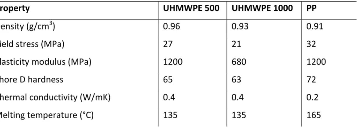
Two grades of ultra-high molecular weight polyethylene (UHMWPE 500 (Docalene HD500) and UHMWPE 1000 (Docalene HD1000)), and one grade of polypropylene (PP (Docapren H)) distributed by Quattroplast Ltd., Hungary and produced by Ensinger GmbH, Germany were used in this study. Some characteristic properties of the test materials are listed in Table
1. Adhesive tests were carried out on rectangular specimens with dimensions of 25.4 x 100 x 2 mm3 cut from extruded plates. For tribological tests, disc samples with a diameter of 10 mm and thickness of 4 mm were fabricated from extruded plates. The surfaces used for adhesive and tribological testing were first polished with silicon carbide abrasive paper (grit number P1200 and 2000) under wet conditions, followed by dry polishing with felt sheet. The samples were subsequently rinsed with distilled water and ethanol. Both for adhesive and tribological testing, standard steel grade S235 (Ferroglobus Ltd., Hungary) was used as a counterface. The steel surfaces were polished with SiC abrasive paper (grit numbers 400 and 600) to an average surface roughness of Ra = 0.07 ± 0.02 µm. Finally, the surface was cleaned by Loctite SF 7063 (Henkel AG & Co., Germany) according to the supplier’s technology.
2.2 Plasma treatment
A diffuse coplanar surface barrier discharge (DCSBD) (manufactured by Roplass s.r.o., Brno, Czech Republic) plasma system was used for surface activation [29-30]. The plasma panel consists of two systems of parallel strip-like electrodes (with typical dimensions of: 1.5 mm wide, 0.5 mm thick, 1 mm strip to strip) embedded in aluminum oxide matrix. The ceramic layer between the plasma and electrodes has a thickness of typically 0.4 mm. The plasma is ignited with a high frequency (10–20 kHz), high voltage with peak-to-peak values of 20 kV.
The elementary discharge involves a diffuse surface discharge developed over the metal electrodes and a filamentary streamer discharge created between the electrodes giving its H shape. Visually homogenous plasma can be reached with increasing voltage and absorbed power as more and more elementary discharges are generated. The applied high voltage may give rise to the heating of the dielectric surface and of the surrounding gas, too. In order to keep the system at the lowest possible temperature oil is circulated over the system, which allows to keep the gas temperature around 320 K. The power of the DCSBD plasma system is set to 320 W, which provided a quasi-homogeneous diffuse plasma with air as process gas.
For plasma treatment, one side of the polymer samples is treated with DCSBD plasma for 3 min. A constant distance of 0.5 mm was kept between the DCSBD surface and the polymer specimen. The latter is constantly moved parallel along the DCSBD surface to provide an even more homogeneous diffuse plasma contact.
2.3 Adhesive testing
For adhesive testing, lap-shear tests were performed according to DIN EN 1465 on single lap joints of polymer/polymer or polymer/steel pairs having a bonded area of 25.4 x 12.5 mm.
Two commercial acrylate adhesives including Loctite 406 (ethyl 2-cyanoacrylate) and Loctite 3035 (two-component glue; Part A: tetrahydrofurfuryl methacrylate, alkyl methacrylate, organoboron amine; Part B: tetrahydrofurfuryl methacrylate, alkyl methacrylate) from the same manufacturer (Henkel AG & Co., Germany) were applied onto the bonded area with a controlled thickness of 0.1 mm. Before using Loctite 406 adhesive, a Loctite 770 primer was applied on the polymer surface according to manufacturer’s recommendation. During curing over a time of 24 h a constant normal load of 5 N was maintained over the bonded area.
Plasma treated samples were glued right after treatment and stored in a plastic box until testing. The pulling tests were carried out using a universal mechanical tensile bench (Zwick Roell Z100, max. 100 kN) with a pulling speed of 1.3 mm/min. The shear strength of the adhesive bond was calculated from the maximum load upon failure with respect to the bonded surface area.
2.4 Tribological testing
Pin-on-disc tests were carried out according to the VI. wear test category (small-scale) of the German standard DIN 50322, using a dynamic tribotester constructed at the Szent István University (Gödöllő, Hungary). The pristine and plasma-treated polymer pins with a diameter of 10 mm and a height of 2 mm were mounted in a stationary holder and were pressed against a rotating steel disc having a polished surface with average roughness Ra = 0.07 to 0.1 µm.
During the measurements the coefficient of friction (µ), the vertical displacement of pin holder (Δh) and the temperature (T) were continuously monitored. Wear was determined from the vertical displacement of the pin holder, which included the real wear and the deformation of the pin. Temperature of the bulk polymer was measured by a thermocouple inserted in the pin 1 mm from the contact zone. Each test was repeated five times to discover the exact trends of friction and wear.
Two types of sliding tests were performed, as follows:
• “Dry” sliding tests consisted of employing a constant sliding velocity v = 0.05 m/s under a stepwise increasing load from p = 0.5 to 1 and 2 MPa (or equivalent pv-conditions 0.025, 0.05 and 0.1 MPa.m/s) over a sliding distance of 60 m (or sliding time of 20 min) for each load. In
this way, the total sliding distance was 180 m and sliding time was 60 min. According to our earlier experiences, the applied time and load level was sufficient to establish steady-state sliding conditions.
• “Run-out” lubricated sliding tests were performed using commercial gearbox oil (SAE 80W90) as lubricant. In the first sliding period (0.5 m distance), a 10 μl oil drop was remotely dropped onto the steel disc by a controlled pipette in front of the polymer contact zone. As such, the first period of the sliding test can be related to the conditions under an oil- lubrication regime. In the second sliding period (9.5 m distance), the lubricant layer was removed by controlled wiping the sliding track on the steel surface with a labor wipe (Kimberly Clark) following the known method applied in [31]. As such, the second period of the sliding test can be considered as representative for a mixed or boundary lubrication regime. However, the exact thickness of the lubricating oil film has not been further assessed due to its permanent change in thickness over time during sliding. The tests were run under a constant sliding velocity v = 0.05 m/s, contact pressure p = 0.5 MPa, and total sliding distance 10 m.
2.3 Surface characterization
The chemical, morphological and energetic properties of the surface either after plasma treatment and/or after wear were determined by X-ray photoelectron spectroscopy (XPS), 3D non-contact optical profilometry (CCI Optics), sessile drop contact angle measurements, Fourier-transform infrared spectroscopy (FTIR), Raman spectroscopy and scanning electron microscopy (SEM).
Contact angles measurements were performed by the static sessile drop method at room temperature using double distilled water and diiodomethane (Sigma–Aldrich, Reagent Plus 99% grade), applying the SEE System apparatus (Advex Instruments, Czech Republic). The measuring liquids were deposited in 2 µl droplets by Hamilton syringe. The calculated contact angle values were presented as the average of five measurements, performed always on previously non-wetted parts of the samples. The surface free energy with its polar and dispersive components was calculated following the Owens-Wendt method [32].
X-ray photoelectron spectra were recorded on a Kratos XSAM 800 spectrometer operating in fixed analyser transmission mode, using Mg Kα1,2 (1253.6 eV) excitation. Survey spectra
were recorded in the kinetic energy range of 150 – 1300 eV with 0.5 eV steps. Photoelectron lines of the main constituent elements, i.e., the O1s, N1s and C1s, were recorded by 0.1 eV steps. The spectra were referenced to the C1s line (binding energy, BE = 285.0 eV) of the hydrocarbon type carbon. A Gaussian-Lorenzian peak shape (70/30 ratio) was used for peak decomposition. Quantitative analysis, based on peak area intensities after removal of the Shirley-type background, was performed by the Kratos Vision 2 and by the XPS MultiQuant programs [33], using experimentally determined photo-ionization cross-section data of Evans et al. [34] and asymmetry parameters of Reilman et al. [35]. Surface chemical compositions were calculated by the conventional infinitely thick layer model, where all components are supposed to be homogeneously distributed within the sampling depth detected by XPS, as calculated by the Layers-on-Plane model.
Surface roughness and topographic analysis were investigated by non-contact profilometry, using a 3D surface optical profilometer Coherence Correlation Interferometry (CCI) HD type (Taylor Hobson) with an ultra-high precision closed loop piezoless z-scanner having a resolution in z-direction of 0.1 Å. A scanned area of 350x350 µm2 was imaged for all samples by vertical scanning interferometry, with an objective lens at 50 x magnification. The images were processed by Talymap software (Digiserve) to calculate the 3D surface roughness parameters including Sa (average roughness), Sz (maximum height). Roughness values were reported as the average of three measurements at independent surface locations, with repeatability Sa < 0.2 Å.
The attenuated total reflection Fourier-transform infrared spectroscopy (ATR-FTIR) was performed on a Brucker Vertex 70 spectrometer, using a diamond ATR crystal and DTGS detector. The spectra were recorded in the wavenumber range 650 to 4000 cm-1 with a resolution of 4 cm-1. The Raman spectroscopy was done on a Perkin Elmer Raman Flex 400 spectrometer with 785 nm laser wavelength having a 40 mW measured laser power output at the sample position. The spectra were recorded at 3200 – 200 cm-1 with a spectral resolution of 4 cm-1. The Raman chemical mapping was done by coupling the laser light into an Olympus BX51 optical microscope with a motorized piezoelectric x,y micro-Raman stage.
While using an objective lens of 20 x (numerical aperture NA = 0.40), a surface area of 5 x 5 mm2 was scanned with a lateral resolution of about 2 µm lateral and depth resolution of about 5 µm. The surface maps were recorded at 25 x 25 points with an interdistance of 0.2 mm with each single spectra recorded with 5 s exposure time and averaged over 3 exposures per point.
Finally, scanning electron microscopy was performed on a Tabletop TM3000 (Hitachi, Germany) equipment without the need for deposition of a conductive gold film on the worn surfaces.
3. Results and discussion
3.1 Water contact angle measurements after plasma treatment
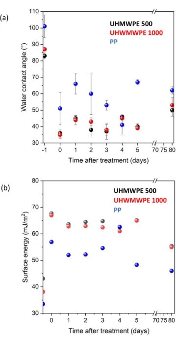
The contact angle values of water and diiodomethane and the calculated surface energy values including both the polar and dispersive components for the pristine and plasma treated samples are summarized in Table 2. Polyolefins are generally considered hydrophobic regarding their high water contact angle values being around 83°, 87° and 101° for UHMWPE 500, UHMWPE 1000 and PP, respectively. The goal of surface treatment commonly is to change the surface wettability and functionalize the surface of the polymers for certain applications. As a result of DBD plasma treatment the contact angles greatly decreased reaching 36, 35 and 52° for UHMWPE 500, UHMWPE 1000 and PP, respectively. Similar considerable decrease in the water contact angle values for PP and PE was found after cold plasma treatment in several research papers as it was compared by Dixon [36]. The surface energies increased accordingly mainly owing to the rise in the polar component. The effect of plasma treatment, however, is abating in long terms as it is indicated by the slight increase of the water contact angle values and variation in surface energies with respect of the days passed after treatment, as followed in Figure 1. This phenomenon was commonly found for plasma treated polymers and was attributed to the surface reactivity and reorientation of polymer chains. The rate of aging can greatly vary and is affected by various factors such as the type of polymer, the applied plasma process, treatment time, etc. [37]. Looking at the measured values in Figure 1 it is worth noting that while restoration of the structure starts quite rapidly and the biggest change in the contact angle occurs within 24 hour, but the increased water contact angle values remained well below that of the pristine polymer even after 3 months. From application point of view the obtained results suggest that any planned follow up processing step (e.g. functionalizing, dyeing, applying adhesives) on the plasma- activated polymers shall be carried out preferably within 24 hour.
3.2 Analysis of surface chemistry after plasma treatment
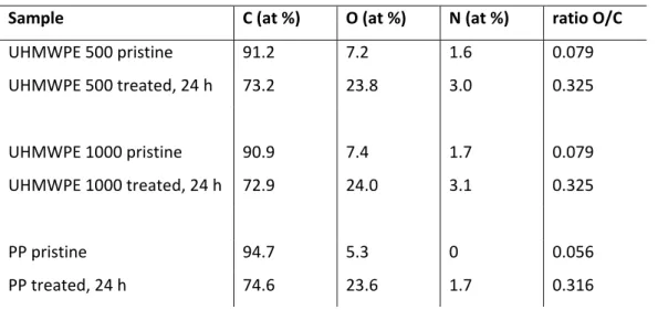
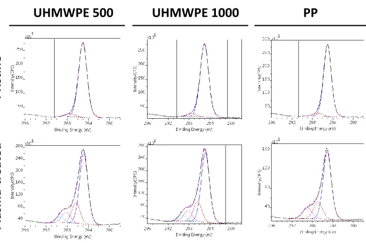
The XPS analysis was performed to monitor the changes in chemical surface composition of the studied polymers after plasma activation. Table 3 shows the elemental composition (at.
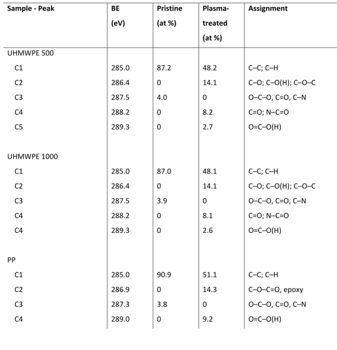
%) of the polymer surfaces before and after plasma treatment calculated from the wide-scan XPS spectra. The presence of oxygen and nitrogen on the pristine polymers results from surface contamination or from the various minor additives typical for polyolefins. Upon plasma treatment the oxygen content increased with parallel drop in the carbon content indicated by the changes of nO/nC atomic ratios. The increased O content suggests the incorporation of oxygen-containing functional polar groups onto the surface that provides reason to the better wettability. The high resolution XPS analysis of C1s spectra (Figure 2) were further analyzed to determine the ratio of the various polar groups developed on the surface. The broad and asymmetric shape of the C1s envelopes could be decomposed into several components (C1, C2, C3, C4, C5). The particular peaks with the corresponding polar groups for the two polymers are summarized in Table 4. The majority of carbon for pristine samples is in C–C and C–H bonding state (predominant peak at 285.0 eV) that was significantly decreased after plasma treatment. In contrast, the ratio of some oxidized functional groups including hydroxyl (OH), carbonyl (C=O), carboxylic acid (O=C–O) increased on the surface. The presence of polar functionalities on the surface is in line with the increased surface wettability experienced from contact angle measurements. These results are in line with findings of earlier papers, [12, 38] even though surface modification was performed by different cold plasma method. In parallel, nitrogen containing functionalities such as OC–N, OC–N–CO could be also detected by XPS in minor amount.
3.3 Surface topography after plasma treatment
Surface topography of pristine and plasma-treated samples monitored by SEM and by 3D surface scans using non-contact profilometry, is illustrated in Figure 3. The 3D surface roughness parameters for Sa (average roughness) and Sz (maximum height) before and after plasma surface treatment are compared in Figure 4.
The two grades of polyethylene (UHMWPE 500 and UHMWPE 1000) and polypropylene (PP) greatly differ in their initial roughness values ranging from Sa = 0.3 µm (PP) to Sa = 1.18 µm (UHMWPE 500), despite of their similar preparation method before plasma treatment. Such difference in the roughness could be expected considering the dissimilar surface hardness and strain capability of the particular polymers during preparation
(machining and polishing). After the plasma surface treatment, an opposing trend can be observed in the topography of the particular polymers. The roughness Sz of the originally polished surface of UHMWPE 500 and UHMWPE 1000 decreased due to the melting and smoothening of the asperities, while the roughness Sz increased for PP due to plasma etching and creation of surface depressions. The DCSBD plasma commonly increases the surface roughness of polymers due to etching effects [39-41], that is more pronounced for the amorphous regions [42]. Treatment in oxygen rich plasma can also create oxidized short polymer fragments, so-called low-molecular weight oxidized materials [43], which can increase the roughness. The mechanical properties and internal stresses can also influence the behaviour of asperities. The melting of surface asperities is more likely for the polyethylenes than for polypropylene (PP) due to the lower melting point of the former. The influences of thermal melting of the surfaces for polyethylenes can be readily seen on the SEM images after plasma treatment.
3.4 Adhesive tests
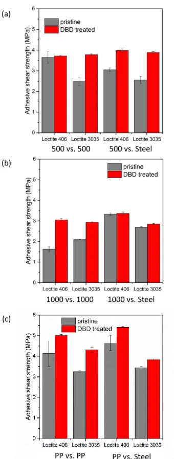
The shear strength of pristine and plasma-treated polymer/polymer and polymer/steel joints evaluated by lap-shear tests is shown for UHMWPE 500 (Figure 5a), 1000 (Figure 5b) and PP (Figure 5c), respectively. In average, the statistical deviation on the shear strength (5 repetitions) has been significantly reduced after plasma treatment, i.e. from about 8 % for pristine samples to 1 % for plasma-treated UHMWPE 500, 2 % for plasma-treated UHMWPE 1000 and 1.5 % for plasma-treated PP. The wetting for most adhesives on polyethylene and polypropylene might be challenging because of their low surface energies of 33 to 43 mN/m respectively. As the critical surface tension for a common ethyl cyanoacrylate adhesive is 33 mN/m or for a methacrylate adhesive is about 28 mN/m, the surface energy of the solid must likely be larger to achieve good wetting. For all testing samples, the adhesive strength for plasma-treated polymers is higher than for the pristine polymer samples. This could be expected from the better wettability and higher surface polarity of the plasma-treated polymer surfaces. The adhesive strength for UHMWPE 1000 samples is somewhat lower that for the UHMWPE 500 samples under all conditions, which relates to the weaker mechanical properties of UHMWPE 1000 besides the surface roughness and energy conditions. The surface energies for UHMWPE 500 and UHMWPE 1000 are indeed in a similar range after plasma treatment, while the high molecular weight may account for reduced adhesion due to limited interdiffusion. The adhesive strength of PP is somewhat higher than that of UHMWPE
500 under all conditions due to the complex result of mechanical properties of the matrix, actual roughness and energies on the surfaces. The total surface energy for PP is indeed considerably lower than that for polyethylenes, which may contribute to worse wetting of the adhesive. The cyanoacrylate adhesive has tendency to exhibit slightly higher shear strength relatively to the methacrylate one for the pristine samples (except UHMWPE 1000 / UHMWPE 1000), while the shear strength became more comparable for the plasma-treated samples. There is a slight tendency that the cyanoacrylate has slightly better performance than the methacrylate adhesive for plasma-treated samples, likely because of the slightly higher surface tension and better wetting.
Failure observed with respect to the different joints and polymers could be attributed to three main types: (i) adhesive failure on the surface of the polymer or steel, (ii) cohesive failure in the adhesive layer inside and (iii) cracking in the bulk polymer. For the pristine and plasma- treated UHMWPE 500, the main cause of the failure was adhesive-type (i) that did not transformed after treatment, however, the failure occurred at higher shear strength. For UHMWPE 1000, adhesive failure transformed into a cohesive one regarding polymer/polymer joints, while no changes could be observed either in the failure mechanism or the adhesion strength for polymer/steel joints. The UHMWPE 1000 has a higher strain and lower E modulus compared to UHMWPE 500 and the roughness increased after plasma treatment for UHMWPE 1000. The contacting zone between the adhesives and asperities (with higher strain of matrix material) could perform stronger bond than the cohesion of the adhesive layer, thus cohesive failure in the adhesive layer was also detectable in UHMWPE 1000 / UHMWPE 1000 joints. For the pristine PP, the typical failure was adhesive type (i) for Loctite 406 and for Loctite 3035 both adhesive (i) and cohesive type (ii). After plasma treatment of PP, the main reason of failure replaced into cohesive (ii) and cracking (type iii) regardless either the type of the surface pairs or of the adhesives. The pure cracking of the bulk polymer corresponds to highest shear strength on plasma-treated surfaces, irrespective of the counterface or adhesive. It was observed that the glue unanimously released easier from the polymer surface and remained sticking on the steel surfaces in case of using dissimilar surface pairs (polymer/steel).
3.5 Tribological tests
3.5.1 Pin-on-disc tribotest under dry conditions
Typical diagrams for coefficients of friction, wear and bulk temperature recorded during dry sliding tests on pristine and plasma-treated specimens under progressively increasing loads are shown for UHMWPE 500 (Figure 6a), UHMWPE 1000 (Figure 6b) and PP (Figure 6c).
The reported curves were not averaged in order to avoid the elimination some typical trends (e.g. fluctuation of coefficient of friction). Confidence interval of the repeated measurements refers to min. 90% significance level.
For pristine samples, the higher coefficients of friction for UHMWPE 500 compared to UHMWPE 1000 are in line with their surface energy values, as the lower total surface energy for UHMWPE 1000 results in lower coefficients of friction. The coefficients of friction for pristine PP, however, are instable and readily increase despites its lower surface energy. For PP, it can be assumed that the higher yield strength and hardness lead to higher sliding resistance and consequently higher coefficients of friction as compared to the polyethylene.
The coefficients of friction for all plasma-treated samples of UHMWPE and PP are considerably higher after plasma treatment as compared to the pristine samples, except for under highest loads where it tends to become roughly identical for PP. The observed tendency can be explained by Archard’s theory of friction claiming that at low mechanical loads, the friction is basically determined by the adhesion of the contact zone instead of deformation.
Indeed, the progressive increase in coefficients of friction as a function of higher normal loads from 1 to 3 MPa suggests that the effects of deformation do not interfere and adhesion is a dominating sliding mechanism (the contribution of visco-elastic deformation would cause a decrease in coefficients of friction at higher loads). It is evident that the increased adhesion processes under sliding for plasma-treated polymers are related to the observed increase in surface energies and adhesive properties of the plasma-treated polymers. Although plasma treatment affected the roughness of the surface, the increased surface energy and as a result the greater adhesion of the surface has dominating effect on the friction. At higher loads, the higher friction for plasma-treated UHMWPE 500 and UHMWPE 1000 suggests that the treated layer did not wear off even at high loads, which was confirmed by the correspondent wear curve. For PP at higher loads, however, the treated layer obviously wears off more frequently and the friction of the pristine and the treated surfaces become more identical as observed for PP (as confirmed by the steep increase in slope of the wear curve for PP at high load, which is likely not attributed to deformation because of the higher yield stress and hardness of PP compared to polyethylenes): similar to friction, wear rates are also much less for polyethylenes than for PP at all load levels.
The bulk temperature of pristine polymers follows the trends of the coefficient of friction. The increasing bulk temperature of the surface treated UHMWPE 500 with respect to load is due to the higher heat loss with rising friction. The bulk temperature rise for UHMWPE 1000 is inferior to that of UHMWPE 500 in parallel with the friction properties. The bulk temperature of pristine PP shows an increasing tendency, while that of UHMWPE 500 remains almost at a plateau level, as the friction for PP rises more frequently. For PP the evolution of temperature curves of the pristine and the plasma-treated specimens are very similar – because of mechanical properties influencing friction as assumed before – but the temperature values are slightly lower after treatment in opposite with the higher friction after treatment. This finding can be attributed to the heat barrier properties of the DCSBD modified layer as was studied and reported in an earlier work [44]. Therefore, the heat generated by friction is accumulated in the contact zone and the counter-surface somewhat better than in the bulk.
3.5.2 Run out type oil lubrication tests
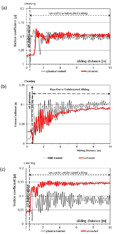
The friction coefficients in oil-lubricated sliding and run-out lubrication conditions are illustrated for the pristine and plasma-treated specimens of UHMWPE 500 (Figure 7a), UHMWPE 1000 (Figure 7b) and PP (Figure 7c). Application of an oil droplet during the first period of sliding resulted in an identically low coefficient of friction (< 0.05) irrespectively of the type of sample and treatment owing to the lubricating action of the oil film. After removing the oil from the surfaces, the coefficients of friction remain considerably lower than those in dry sliding conditions. Similar to results under dry sliding conditions, friction of UHMWPE 1000 is lower than UHMWPE 500 and friction of UHMWPE 500 is much less than that of PP after cleaning the sample. The lower friction under run-out conditions can be ascribed to the oil retention ability of the polymer surface. Combination of the modified microgeometry and the increased surface energy of the plasma treated polymers favorably enhances the adsorption of the oil lubricant on the polymer surface and entrapment in the interface. In particular, the increase in surface energy may be beneficial for better adsorption of the hydrophobic oil lubricant at the surface. As the roughness of plasma-treated samples varied differently for polyethylenes (decrease in roughness Sz for plasma-treated UHMWPE 500, UHMWPE 1000) and polypropylene (increase in roughness Sz for plasma- treated PP) relatively to the pristine samples, the lower surface roughness for plasma-treated polyethylenes obviously opposed oil entrapment with higher coefficients of friction, while the higher surface roughness for plasma-treated PP obviously enhanced the entrapment of oil with lower coefficients of friction. In parallel, the considerable fluctuations in the friction indicate
the effect of the varying layer of the lubricant. During “run-out” the mixed friction regime approaches toward the boundary lubrication and with decreasing thickness of the lubricant layer the friction became stabilized at a lower level as compared to the pristine sample.
3.6 Evaluation of worn surfaces
The evaluation of worn surfaces (pristine and plasma-treated) after dry and run-out lubricated sliding by SEM is illustrated in Figure 8 at different magnifications (800 x, 2000 x). It is confirmed that the main wear processes are caused by adhesive wear as stated in explanation of trends for coefficients of friction. The pristine dry worn surfaces show less wear damage compared to the plasma-treated dry worn surfaces. The severe wear tracks on plasma-treated dry surfaces are in agreement with the higher coefficients of friction and wear rates recorded for plasma-treated samples. For pristine samples, the UHMWPE 1000 shows smoother surfaces than UHMWPE 500 in agreement with the lower coefficients of friction. For plasma- treated samples, the more severe wear tracks of UHMWPE 500 and UHMWPE 1000 point towards adhesive types of wear with formation of an polymer film at the surface. The PP shows more severe adhesive wear marks as friction was highest. The worn surfaces after run- out lubricated sliding are obviously smoother than under dry sliding.
The evaluation of worn surfaces (pristine and plasma-treated) after dry sliding by means of FTIR spectroscopy is presented in Figure 9. For UHMWPE, the introduction of functional groups is observed through the occurrence of absorption bands at 1740 cm-1 (esters) and eventually 1720 to 1710 cm-1 (acids, ketones, carboxylic acids). The additional band at 1648 cm-1 corresponds to COO- asymmetrical stretching and the one at 1368 cm-1 (broadening of the peak) may be due to the COO- symmetrical stretching. The carbonyl functional groups (C=O) are typically associated with oxidative degradation products, and are observed both after plasma treatment and after wear as an indication for the surface degradation by these processes. The latter remains present after wear of plasma-treated surfaces and confirms that wear remains below the surface depth that was modified through plasma modification. For UHMWPE 500, a higher amount of low-molecular acids and ketones remains present at worn plasma-treated surface likely contributing to the lower coefficients of friction. For UHMWPE 1000, the weaker mechanical structure evidently results in a higher amount of surface degradation by plasma, but the layer is more easily removed under sliding. In addition, an increase in the absorbance in the 1400 to 1180 cm-1 region (–C-O-C vibrations) and 800 to 1100 cm-1 (unsaturated C=C vibrations) indicates further degradation of the polymer surface
through oxidation. A further detail of variations in the bands at 730 and 718 cm-1 (see Figure 10) indicate differences in crystalline structure of the UHMWPE 1000, with the band at 730 cm-1 indicating crystalline a-axis and 718 cm-1 indicating crystalline b-axis orientation. As the peak at 730 cm-1 shows up more frequently after plasma treatment and after wear, degradation processes are associated with a progressive reorientation of the carbon chains preferentially along the crystalline a-axis. The distortion in molecular structure of the polymer backbone (particularly after sliding) is further confirmed by a significant shift in the methylene C-H stretching band, which is located at 1463 cm-1 for pristine and plasma-treated UHMWPE 1000, or at 1458 cm-1 for both worn UHMWPE 1000 samples. These variations were not intensively observed in the UHMWPE 500 samples. For PP, surface degradation after plasma treatment is more prevalent compared to the polyethylenes, while the surface-modified layer is worn off after sliding and variations in crystallinity are not explicitly noticed.
The chemical surface mapping worn surfaces (pristine and plasma-treated) after dry sliding by means of Raman spectroscopy is presented in Figure 11 (the original Raman spectra are shown in Supplementary Information S1). The effects of plasma treatment and wear are indicated by average intensity maps over the surface, after baseline correction and normalization of the spectra on the Raman shift range 1400 – 1500 cm-1. The variations in surface intensity after plasma treatment clearly indicate local differences in chemical surface composition that are more intense for UHMWPE 1000 than for UHMWPE 500 in parallel with previous infrared spectroscopy and attributed to the weaker mechanical properties of the UHMWPE 1000. The most intense surface modification of PP has also been confirmed in the infrared spectroscopy. The surface modifications after wear of pristine samples is evidently larger for UHMWPE 500 than for UMHPWE 1000 in parallel with the observations of higher friction for UHMWPE 500. The severe surface damage after wear for plasma-treated surfaces reflects the higher coefficients of friction, in particular the formation of adhesive ‘flake-like’
deposits on UHMWPE 500 en more characteristic wear tracks on PP as seen on the SEM images.
4. Conclusions
The atmospheric air dielectric coplanar surface barrier discharge (DCSBD) plasma treatment induced a series significant change on the surface of investigated polyolefins (UHMWPE 500, UHWMPE 1000 and PP), in relation with observed tribological properties:
• XPS and FTIR analysis revealed the formation of various oxygen containing functionalities such as hydroxyl, carbonyl and carboxyl groups on the topmost surface of the polymers after plasma modification.
• Surface energy considerably increased in parallel with improved wettability for right after treatment due to the developed polar groups. The as-developed hydrophilicity starts to decline right after treatment and the WCA values increased significantly within a few days but remained far below that of the pristine polymers even after 3 months.
• From analysis of 3D surface topography, the roughness of the originally polished surface of UHMWPE decreased due to the melting of asperities, while that of the PP increased a little likely to the dominating etching effect of the plasma.
• Plasma treatment had a great benefit for adhesion properties for both polymers. Not only the adhesive shear strength of the polymer/polymer and polymer/steel joints increased but the surface treatment also improved the reliability of the joint that could be manifested by the much smaller standard deviation of the measured values.
• Friction coefficient in dry sliding conditions on plasma-treated surfaces slightly got higher as the consequence of the improved adhesion. Upon oil lubrication, however, friction significantly decreased for both polymers. Moreover, the reached lower friction was maintained after cleaning the oil likely due to the higher oil retaining capability of the treated surfaces.
The observed trends in friction and wear for different polyolefins before and after plasma treatment were confirmed by spectroscopic analysis of the surfaces.
Acknowledgement
The authors acknowledge the financial support of NKFIH (No. K 113039).
Conflict of interest
The authors confirm that there are no known conflicts of interest associated with this publication and there has been no significant financial support for this work that could have influenced its outcome.
References
1. Baldan A.: Adhesively‐bonded joints in metallic alloys, polymers and composite materials:
Mechanical and environmental durability performance. Journal of Materials Science, 39, 4729–4797 (2004).
doi: 10.1023/B:JMSC.0000035317.87118.ab
2. Mandolfino C., Lertora E., Gambaro C., Bruno M.: Improving adhesion performance of polyethylene surfaces by cold plasma treatment. Meccanica, 49, 2299–2306 (2014).
doi: 10.1007/s11012‐014‐9993‐y
3. Samad MA., Sinha SK.: Mechanical, thermal and tribological characterization of a UHMWPE film reinforced with carbon nanotubes coated on steel. Tribology International, 44, 1932–
1941 (2011).
doi: 10.1016/j.triboint.2011.08.001
4. Horakova M., Spatenka P., Hladik J., Hornik J., Steidl J., Polachova A.: Investigation of adhesion between metal and plasma‐modified polyethylene. Plasma Procesess and Polymers, 8, 983–988 (2011).
doi: 10.1002/ppap.201100045
5. Abdul Samad M, Satyanarayana N, Sinha SK.: Tribology of UHMWPE film on air‐plasma treated tool steel and the effect of PFPE overcoat. Surface Coatings and Technology 204, 1330–1338 (2010).
doi: 10.1016/j.surfcoat.2009.09.011
6. Van Vrekhem S, Cools P, Declercq H, Van Tongel A., Vercruysse C., Cornelissen M., De Geyter N., Morent R.: Application of atmospheric pressure plasma on polyethylene for increased prosthesis adhesion. Thin Solid Films, 596, 256–263 (2015).
doi: 10.1016/j.tsf.2015.08.055
7. Blackman BRK, Guild FJ.: Forced air plasma treatment for enhanced adhesion of
polypropylene and polyethylene. Journal of Adhesion Science and Technology, 27, 2714–
2726 (2013).
doi: 10.1080/01694243.2013.808959
8. Favia P, Oehr C, Wertheimer MR.: Plasma processes and polymers. Wiley‐VCH, Weinheim (2005).
9. Kusano Y Atmospheric Pressure Plasma Processing for Polymer Adhesion: A Review. The Journal of Adhesion, 90, 755–777 (2014).
doi: 10.1080/00218464.2013.804407
10. Thomas M, Mittal KL Atmospheric Pressure Plasma Treatment of Polymers: Relevance to Adhesion. Wiley Blackwell, Weinheim (2013).
11. Bárdos L, Baránková H.: Cold atmospheric plasma: Sources, processes, and applications. Thin Solid Films, 518, 6705–6713 (2010)
doi: 10.1016/j.tsf.2010.07.044
12. Kostov KG, Nishime TMC, Castro AHR, Toth A, Hein LRO.: Surface modification of polymeric materials by cold atmospheric plasma jet. Applied Surface Science, 314, 367‐375 (2014).
doi.:10.1016/j.apsusc.2014.07.009
13. Shaw D, West A, Brendin J, Wagenaars E.: Mechanisms behind surface modification of polypropylene film using an atmospheric‐pressure plasma jet, Plasma Sources Science and Technology, 25, 065018 (2016).
doi: 10.15124/5084b572‐7e46‐4a8d‐9a7a‐b69683127817
14. Lambare C, Tessier P‐Y, Poncin‐Epaillard F, Debarnot D: Plasma functionalization and etching for enhancing metal adhesion onto polymeric substrates. RSC Advances 5,62348–62357 (2015).
doi: 10.1039/C5RA08844E
15. Wang K, Li J, Ren C, Wang D, Wang Y.: Surface modification of polyethylene (PE) films using dielectric barrier discharge plasma at atmospheric pressure, Plasma Science and Technology, 10, 433–437 (2008).
doi:10.1088/0169‐5983/44/3/031404
16. Sun X, B. Zhang B, Sun B.: Surface modification of polyethylene in dielectric barrier discharge (DBD) plasma under atmospheric‐pressure, International Journal of Engineering Innovation &
Research 5, 164‐167 (2016).
17. Nihlstrand A, Hjertberg T, Johansson K.: Plasma treatment of polyolefins: influence of material composition: 1. bulk and surface characterization, Polymer 38, 3581‐3589 (1997).
doi:10.1016/S0032‐3861(96)00930‐5
18. Kereszturi K, Tóth A, Mohai M, Bertóti I, Szépvölgyi J.: Nitrogen plasma‐based ion implantation of poly(tetrafluoroethylene): Effect of the main parameters on the surface properties. Applied Surface Science 256, 6385–6389 (2010).
doi: 10.1016/j.apsusc.2010.04.021
19. Tóth A, Kereszturi K, Mohai M, Bertóti I.: Plasma based ion implantation of engineering polymers. Surface Coatings and Technology, 204, 2898–2908 (2010).
doi: 10.1016/j.surfcoat.2009.12.004
20. Kalácska G, Zsidai L, Kereszturi K, Mohai M, Tóth A.: Sliding tribological properties of untreated and PIII‐treated PETP. Applied Surface Science, 255, 5847–5850 (2009).
doi: 10.1016/j.apsusc.2009.01.017
21. Bertóti I, Mohai M, Tóth A, Ujvári T.: Nitrogen‐PBII modification of ultra‐high molecular weight polyethylene: Composition, structure and nanomechanical properties. Surface Coatings and Technology, 201, 6839–6842 (2007).
doi: 10.1016/j.surfcoat.2006.09.022
22. Zhang J.: Surface modification of ultra‐high‐molecular‐weight polyethylene by argon plasma, Journal of Thermoplastic Composite Materials , 27, 758‐764 (2014).
doi: 10.1177/0892705712454868
23. Liu H, Pei Y, Xie D, Deng X, Leng YX, Lin Y, Huang N.: Surface modification of ultra‐high molecular weight polyethylene (UHMWPE) by argon plasma, Applied Surface Science, 256, 3941‐3945 (2010).
doi:/10.1016/j.apsusc.2010.01.054
24. Kumar NN, Yap SL, Samsudin FND, Khan MZ, Srinivasa RSP.: Effect of argon plasma treatment on tribological properties of UHMWPE/MWCNT nanocomposites, Polymers, 8, 295 (2016).
doi:10.3390/polym8080295
25. Poncin‐Epaillard F, Brosse JC, Falher T.: Reactivity of surface groups formed onto a plasma treated poly(propylene) film. Macromolecular Chemistry and Physics, 200, 989–996 (1999).
doi: 10.1002/(SICI)1521‐3935(19990501)200:5<989::AID‐MACP989>3.0.CO;2‐M
26. Pandiyaraj KN, RamKumar MC, Arun Kumar A, Padmanabhan PVA, Deshmukh RR, Bendavid A, Su PG, Sachdev A, Gopinath P.: Cold atmospheric pressure (CAP) plasma assisted tailoring of LDPE film surfaces for enhancement of adhesive and cytocompatible properties: Influence of operating parameters. Vacuum, 130, 34–47 (2016).
doi: 10.1016/j.vacuum.2016.04.029
27. Van Deynse A, Cools P, Leys C, De Geyter N, Morent R.: Surface activation of polyethylene with an argon atmospheric pressure plasma jet: Influence of applied power and flow rate.
Applied Surface Science, 328, 269–278 (2015).
doi: 10.1016/j.apsusc.2014.12.075
28. Bismarck A, Brostow W, Chiu R, Hagg Lobland HE, Ho KCK.: Effects of surface plasma
treatment on tribology of thermoplastic polymers. Polymer Engineering & Science, 48, 1971–
1976 (2008).
doi: 10.1002/pen.21103
29. Šimor M, Ráhel’ J, Vojtek P, Černak M.: Atmospheric‐pressure diffuse coplanar surface discharge for surface treatments. Applied Physics Letters, 81, 2716–2718 (2002).
doi: 10.1063/1.1513185
30. Černák M, Černáková L, Hudec I, Kováčik D, Zahoranová A.: Diffuse Coplanar Surface Barrier Discharge and its applications for in‐line processing of low‐added‐value materials. European Physical Journal: Applied Physics, 47, 22806 (2009).
doi: 10.1051/epjap/2009131
31. Kalácska G, Zsidai L, Keresztes R, Tóth A, Mohai M, Szépvölgyi J.: Effect of nitrogen plasma immersion ion implantation of polyamide‐6 on its sliding properties against steel surface.
Wear, 290–291, 66–73 (2012).
doi: 10.1016/j.wear.2012.05.011
32. Owens DK, Wendt RC.: Estimation of the surface free energy of polymers. Journal of Applied Polymer Science, 13, 1741–1747 (1969).
doi: 10.1002/app.1969.070130815
33. Mohai M.: XPS MultiQuant: multimodel XPS quantification software. Surface Interface Analysis, 36, 828–832 (2004).
doi: 10.1002/sia.1775
34. Evans S, Pritchard RG, Thomas JM.: Relative differential subshell photoionisation cross‐
sections (MgKα) from lithium to uranium. Journal of Electron Spectroscopy and Related Phenomena, 14, 341–358 (1978).
doi: 10.1016/0368‐2048(78)80008‐5
35. Reilman RF, Msezane A, Manson ST.: Relative intensities in photoelectron spectroscopy of atoms and molecules. Journal of Electron Spectroscopy and Related Phenomena, 8, 389–394 (1976).
doi: 10.1016/0368‐2048(76)80025‐4
36. Dixon D, Meenan BJ.: Atmospheric Dielectric Barrier Discharge Treatments of Polyethylene, Polypropylene, Polystyrene and Poly(ethylene terephthalate) for Enhanced Adhesion. Journal of Adhesion Science and Technology, 26, 2325–2337 (2012).
doi: 10.1163/156856111X599481
37. Novák I, Popelka A, Valentín M, Chodák I, Špírková M, Tóth A, Kleinová A, Sedliačik J. Lehocký M, Marônek M.: Surface Behavior of Polyamide 6 Modified by Barrier Plasma in Oxygen and Nitrogen. International Journal of Polymer Analysis and Characterization, 19, 31–38 (2014).
doi: 10.1080/1023666X.2014.850907
38. Bertóti I, Mohai M, László K.: Surface modification of graphene and graphite by nitrogen plasma: Determination of chemical state alterations and assignments by quantitative X‐ray photoelectron spectroscopy. Carbon, 84,185–196 (2015).
doi: 10.1016/j.carbon.2014.11.056
39. Yeh JT, Lai YC, Suen MC, Chen CC.: An improvement on the adhesion‐strength of laminated ultra‐high‐molecular‐weight polyethylene fabrics: Surface‐etching/modification using highly effective helium/oxygen/nitrogen plasma treatment. Polymer Advanced Technology, 22, 1971–1981 (2011).
doi: 10.1002/pat.1703
40. Tosun K, Felekoğlu B, Baradan B.: Multiple cracking response of plasma treated polyethylene fiber reinforced cementitious composites under flexural loading. Cement and Concrete Composites, 34, 508–520 (2012).
doi: 10.1016/j.cemconcomp.2011.12.001
41. Navaneetha Pandiyaraj K, Arun Kumar A, RamKumar MC, Deshmukh RR, Bendavid A, Su PG, Kumar SU, Gopinath P Effect of cold atmospheric pressure plasma gas composition on the surface and cyto‐compatible properties of low density polyethylene (LDPE) films. Current Applied Physics, 16, 784–792 (2016).
doi: 10.1016/j.cap.2016.04.014
42. López R, Sanchis R, García D, Fenollar O, Balart R.:Surface characterization of hydrophilic coating obtained by low‐pressure CH4–O2 plasma treatment on a polypropylene film. Journal of Applied Polymer Science, 111, 2992–2997 (2009).
doi: 10.1002/app.29324
43. Kostov KG, Nishime TMC, Hein LRO, Toth A.: Study of polypropylene surface modification by air dielectric barrier discharge operated at two different frequencies. Surface Coatings and Technology, 234, 60–66 (2013).
doi: 10.1016/j.surfcoat.2012.09.041
44. Kalácska G, Keresztes R, Földi L, Klébert Sz, Károly Z, Zsidai L.: Thermal conductivity of plasma modified polyethylene terephthalate and polyamide‐6 layers. Express Polymer Letters, 10, 373–380 (2016).
doi: 10.3144/expresspolymlett.2016.35
Figure Captions
Fig. 1 Water contact angle values of the studied polymers after DCSBD plasma treatment as a function of time, (a) water contact angle, (b) calculated surface energy
Fig. 2 Chemical surface analysis by XPS (C 1s spectra) of pristine and DCSBD plasma‐treated surfaces
Fig. 3 Topographical surface analysis by SEM and non‐contact profilometry of pristine and DCSBD plasma‐ treated surfaces for PE UHMWPE and PP
Fig. 4 Major surface roughness parameters of pristine and DCSBD plasma‐treated surfaces for UHMWPE and PP
Fig. 5 Adhesive shear strength of pristine (grey) and plasma‐treated (red) polymer/polymer and polymer/steel joints using different adhesives for (a) UHMWPE 500, (b) UHMWPE 1000, (c) PP
Fig. 6 Tribological properties of pristine and DCSBD plasma treated polymer/steel pairs in dry conditions as a function of sliding distance (p = 0.5, 1, 2 MPa; v = 0.05 m s‐1) for (a) PE, (b) UHMWPE, (c) PP
Fig. 7 Coefficient of friction of pristine and plasma‐treated polymer/steel pairs under lubricated
sliding and run‐out conditions as a function of sliding distance (p=0.5 MPa; v=0.05 m s‐1) for (a) UHMWPE 500, (b) UHMWPE 1000, (c) PP
Fig. 8 SEM evaluation of pristine and plasma‐treated worn surfaces
Fig. 9 ATR‐FTIR surface analysis of native and worn polymer surfaces, (a) UHMWPE 500, (b) UHMWPE 1000, (c) PP
Fig. 10 Detailed variations in ATR‐FTIR evaluation of UHMWPE 1000 surfaces Fig. 11 Chemical Raman mapping of native and worn polymer surfaces
Table 1. Characteristic properties of testing materials
Property UHMWPE 500 UHMWPE 1000 PP
Density (g/cm3) 0.96 0.93 0.91
Yield stress (MPa) 27 21 32
Elasticity modulus (MPa) 1200 680 1200
Shore D hardness 65 63 72
Thermal conductivity (W/mK) 0.4 0.4 0.2
Melting temperature (°C) 135 135 165
Table 2. Contact angle values and surface energy values of the pristine polymers and plasma treated samples measured at certain times after treatment
Sample θw
(°)
θCH2l2 (°)
γpol (mJ/m2)
γdisp (mJ/m2)
γtot (mJ/m2)
UHMWPE 500 pristine 83±1.8 38±3.3 2.4 40.7 43.1
UHMWPE 500 treated, 5 min 36±2.4 29±2.7 22.9 44.9 67.7 UHMWPE 500 treated, 24 h 45±1.8 28±1.1 18.5 45.0 63.6
UHMWPE 1000 pristine 87±0.4 47±1.9 1.9 36.2 38.1
UHMWPE 1000 treated, 5 min 35±2.3 35±5.8 24.7 42.2 67.0 UHMWPE 1000 treated, 24 h 38±3.3 48±1.3 26.9 35.5 62.4
PP pristine 101±6.9 52±2.6 0.1 33.4 33.5
PP treated, 5 min 51±9.9 41±1.6 17.8 39.1 56.9
PP treated, 24 h 66±6.2 30±3.9 7.7 44.3 52.0
Table 3. Surface composition of the pristine polymers and plasma treated samples determined by XPS analysis
Sample C (at %) O (at %) N (at %) ratio O/C
UHMWPE 500 pristine 91.2 7.2 1.6 0.079
UHMWPE 500 treated, 24 h 73.2 23.8 3.0 0.325
UHMWPE 1000 pristine 90.9 7.4 1.7 0.079
UHMWPE 1000 treated, 24 h 72.9 24.0 3.1 0.325
PP pristine 94.7 5.3 0 0.056
PP treated, 24 h 74.6 23.6 1.7 0.316
Table 4. The results of quantification and peak assignment of C1s components of the pristine polymers and plasma treated samples by XPS analysis
Sample ‐ Peak BE
(eV)
Pristine (at %)
Plasma‐
treated (at %)
Assignment
UHMWPE 500
C1 C2 C3 C4 C5
UHMWPE 1000 C1
C2 C3 C4 C4 PP
285.0 286.4 287.5 288.2 289.3 285.0 286.4 287.5 288.2 289.3
87.2 0 4.0 0 0 87.0 0 3.9 0 0
48.2 14.1 0 8.2 2.7 48.1 14.1 0 8.1 2.6
C–C; C–H
C–O; C–O(H); C–O–C O–C–O, C=O, C–N C=O; N–C=O O=C–O(H)
C–C; C–H
C–O; C–O(H); C–O–C O–C–O, C=O, C–N C=O; N–C=O O=C–O(H)
C1 C2 C3 C4
285.0 286.9 287.3 289.0
90.9 0 3.8 0
51.1 14.3 0 9.2
C–C; C–H
C–O–C=O, epoxy O–C–O, C=O, C–N O=C–O(H)
Fig. 1 Water contact angle values of the studied polymers after DCSBD plasma treatment as a function of time, (a) water contact angle, (b) calculated surface energy
(a)
(b)
UHMWPE 500 UHWMWPE 1000 PP
UHMWPE 500 UHWMWPE 1000 PP
Fig. 2 Chemical surface analysis by XPS (C 1s spectra) of pristine and DCSBD plasma-treated surfaces
UHMWPE 500 UHMWPE 1000 PP
Pristin e Pl as ma -treate d
Fig. 3 Topographical surface analysis by SEM and non-contact profilometry of pristine and DCSBD plasma- treated surfaces for PE UHMWPE and PP
Plasma-treated Pristine
P P UHM WP E 500 UHM WP E 1 0 0 0
Fig. 4 Major surface roughness parameters of pristine and DCSBD plasma-treated surfaces for UHMWPE and PP
UHMWPE 500 UHMWPE 1000 PP
Fig. 5 Adhesive shear strength of pristine (grey) and plasma-treated (red) polymer/polymer and polymer/steel joints using different adhesives for (a) UHMWPE 500, (b) UHMWPE 1000, (c) PP
(b) (a)
(c)
500 vs. 500 500 vs. Steel
1000 vs. 1000 1000 vs. Steel
PP vs. PP PP vs. Steel
Fig. 6 Tribological properties of pristine and DCSBD plasma treated polymer/steel pairs in dry conditions as a function of sliding distance (p = 0.5, 1, 2 MPa; v = 0.05 m s-1) for (a) PE, (b) UHMWPE, (c) PP
UHMW PE 5 0 0 UHMW PE 1 0 00 PP
(a)(b)(c)Fig. 7 Coefficient of friction of pristine and plasma-treated polymer/steel pairs under lubricated sliding and run-out conditions as a function of sliding distance (p=0.5 MPa; v=0.05 m s-1) for (a) UHMWPE 500, (b) UHMWPE 1000, (c) PP
(c) (b)
(a)
-
Fig. 8 SEM evaluation of pristine and plasma-treated worn surfaces
UHMWPE 1000
UHWMPE 500
PP Plasma -treate d d ry worn Pri stin e d ry wo rn
Plasma -treate lu b ricat e d w orn
Fig. 9 ATR-FTIR surface analysis of native and worn polymer surfaces, (a) UHMWPE 500, (b) UHMWPE 1000, (c) PP
(b)
UHMWPE 1000
pristine pristine worn plasma-treated plasma-treated worn
pristine
PP
(c)
plasma-treated worn plasma-treated pristine worn
UHMWPE 500
plasma-treated plasma-treated worn
1463 718730
1740 1648 1368
Fig. 10 Detailed variations in ATR-FTIR evaluation of UHMWPE 1000 surfaces Wavenumber (cm-1)
800 750 700 650 600
pristine pristine worn plasma-treated
plasma-treated worn
1400 1450
1500 1550
1600
Wavenumber (cm-1)
pristine worn
plasma-treated worn pristine
plasma-treated
UHMWPE 1000 UHMWPE 1000
Fig. 11 Chemical Raman mapping of native and worn polymer surfaces