H
AVASII
STVÁN, B
ARTHAG
ÁBOR,
I NTRODUCTION TO GIS
2
II. S
ATELLITEG
LOBALP
OSITIONINGS
YSTEMS1. GPS
TECHNIQUEThe widespread use of 3D satellite global positioning systems all over the world has revolutionized not only geodesy and surveying but also has offered a totally new alternative surveying technique to geometric data capture for GIS.
Nowadays, the best known among the operating systems are NAVSTAR-GPS (NAVigation Satellite Timing And Ranging Global Positioning System, known more briefly as GPS) and GLONASS (GLObal NAvigation Satellite System - briefly GLONASS). The first system was developed by the USA, the second one by the Soviet Union starting in the early 1970s for navigation purposes, primarily for military users. The satellite constellation of these systems can be seen in Figure 2.1.
Figure 2.1. The space segments of GPS and GLONASS
We can say, in general, about NAVSTAR GPS that this system is already widely known indeed, and it has become perhaps the most influential surveying technique. The development of GPS is unbroken (continuous modernization of the system is ongoing today as well), and its future seems to be bright.
The now Russian GLONASS, the other mentioned navigation satellite system, in contrast to GPS, is less known, and in its history it has run into numerous troubles; therefore, you can find positive and negative trends in its life.
Nowadays, GLONASS has been developing dynamically. Formerly, the vision of the future of this system – compared to GPS – seemed to be quite uncertain. Full development of the present uncompleted constellation is expected to be accomplished in the near future.
In addition to the afore-mentioned two fundamental systems, the development of a new second-generation satellite system, Galileo, related to the European Union, is in progress. Originally, the realization of Galileo was planned in 2008 and its operational stage for our recent days; however, these ideas were not completed due to economic reasons. Therefore, the introduction of a satellite global positioning system related to the EU is significantly delayed.
In 2000 China also decided to participate in developing a satellite global positioning system. First, this Asian country realized a military, so-called ‘domestic system’ – BEIDUO – and then, besides operating the former system, started to develop a new fundamental system called Compass, which is very similar to GPS and GLONASS considering its working principle.
2. H
ISTORYOF SATELLITEGLOBALPOSITIONING SYSTEMSThe principle of satellite global positioning is based on ranging with radio waves. This surveying procedure makes it
possible for a GPS receiver to pick up and evaluate the complex signals sent out by the satellites designed for this purpose, and then display the geocentric coordinates fixing the receiver antenna. It is known that radio waves are a kind of electromagnetic waves whose wavelengths – considering their whole spectrum – spread from some millimetres to several kilometres. GPS signals have a decimetre wavelength. Today, navigation can be considered to be the most widespread application of GPS technique. The development of satellite-based positioning is also motivated by navigation, especially by military use. Among the first results of radio navigation can be mentioned the terrestrial off- shore systems which have been developed dynamically from the end of the Second World War. Among the so-called
‘western systems’ for example the Syledis (f = 400 MHz, = 0,75m, = 1m) planned for a 100-km range is well known. In the technical competition, naturally, the Soviet Union did not want to lose either, and therefore developed its own system called ‘Chayka’ at nearly the same time, the terrestrial stations of which were connected to the Baltic Sea.
The surveying procedure was a so-called ‘resection’ by means of ranges where the coordinates fixing the position of a vehicle in question were computed from distance measurements to three reference stations. To the one-way ranging unified time (system time) was needed, that is to say the atomic clocks of each reference station had to be synchronized. The application limits of these systems can be mainly defined by their range and accuracy, which is strongly related to the afore-mentioned parameter.
With the launch of the first artificial satellite (Sputnik I) on the 4th of October 1957 the Soviet Union triggered the so- called ‘space era’. The appearance of artificial satellites brought possibilities to carry the development of radio navigation systems further as well. Instead of former terrestrial control points the use of ‘celestial control points’ was started and thereby the revolutionary development of satellite radio navigation was launched.
The first artificial radio navigation system was developed by the USA. Its name was TRANSIT (Navy Navigation Satellite System, shortly NNSS) and its primary goal was positioning submarines. The Soviet Union also started the development of a sister system called Chikada (‘Cricket’) a little bit earlier. The NNSS system was operated in its essentials to meet the original goals until the mid-nineties.
The main characteristics of the TRANSIT system, realized in 1964, are collected in Table 2.1.
The TRANSIT global positioning system
number of satellites 4-6
orbital altitude 1000 km
rotation time 105 minutes
carrier frequencies 150 MHz and 400 MHz
on-board clock quartz
measured data changes in satellite-receiver distance
(application of Doppler-techniques)
positioning 2D position
observation 1 satellite (1.5 hour; 15-20 minute transition)
accuracy absolute: 30-40 m, relative: 1-3 m
application maritime, geodynamical, scientific
Table 2.1. Some main features of the TRANSIT system
The greatest disadvantage of the TRANSIT system lies in the fact that the continuous observation of the satellites was not guaranteed.
The development of NAVSTAR GPS providing global coverage and thereby continuous positioning started in 1973.
Reacting to this technical challenge and the demands from its army, the Soviet Union issued a Declaration on establishing the GLONASS sister system in 1976. Since this time the development of the two best-known operating satellite fundamental systems has been being ongoing.
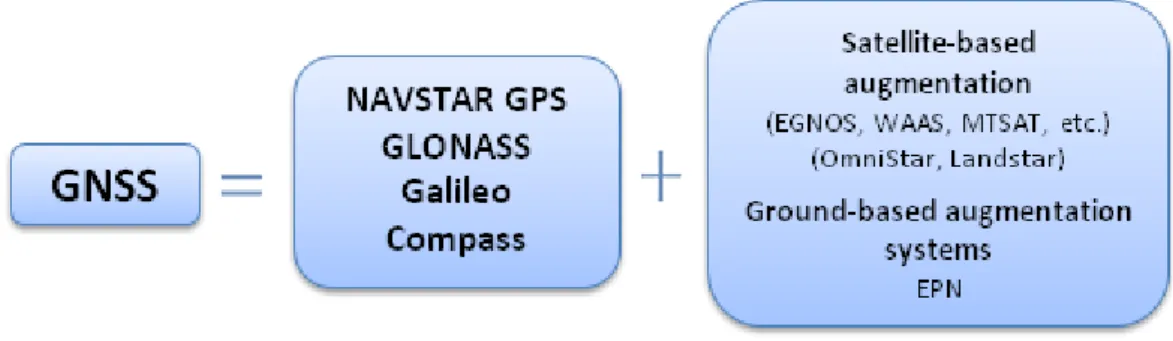
Definition of GNSS, satellite fundamental and augmentation systems
The acronym GNSS means Global Navigation Satellite System in Hungarian practice as well. The expression GNSS
covers fundamental systems which are already operating (e.g. NAVSTAR GPS) or under development (e.g. Galileo) furthermore, it includes augmentation systems depending on the afore-mentioned ones (e.g. EGNOS). A description of all of these in a mathematical formula can be seen in Figure 2.2.
Figure 2.2. Fundamental and augmentation systems building up the GNSS
After reviewing GNSS – without aiming at completeness – let us give some features of the fundamental systems:
providing 3D position, time, actual velocity;
global coverage, which means simultaneous operation of at least 24 satellites;
independence of time of the day and weather conditions;
continuous service all over the world where it can be provided by surveying conditions (a clear view of the sky is needed),
the base service is provided freely by the system management, etc.
As far as augmentation systems are concerned their purpose, primarily, is to increase the accuracy of the fundamental systems and improve their integrity and availability. The word integrity may seem like an unusual expression in this context. What do we mean by integrity in connection with GPS technique? This is an expression related to the navigation application of GPS, which includes a warning message for a case when the system is not reliable for any reason.
Characteristics and segments of NAVSTAR GPS fundamental system
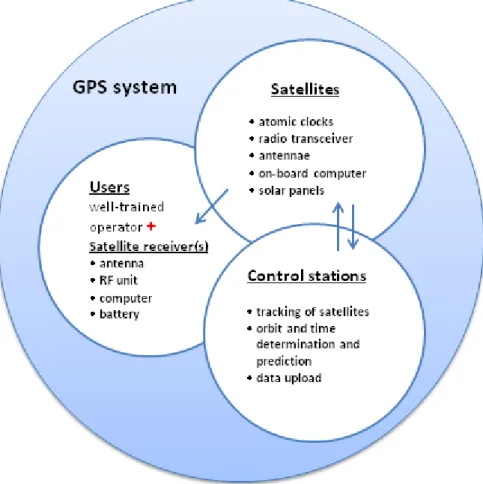
NAVSTAR GPS is a first generation American satellite fundamental system which – as we mentioned earlier – is a result of military development. The system has been operating continuously and in a reliable way since its realization, satisfying a wide circle of various users today. The fundamental system itself consists of three subsystems (segments).
These are the space segment, the control segment and the user segment. The strong relations among each segment are shown in Figure 2.3.
Figure 2.3. The structure of GPS system
The space segment means the mass of satellites rotating in known orbits around the Earth. Both the number of orbital planes (6) and allocation of satellites in each plane serve the purpose that lets a minimum of 4 satellites be in view at any location on the Earth at the same time, that is to say, lets those be allocated 15º above the horizon. For the configuration planned, meeting the previous condition therefore means a minimum of 24 operating satellites simultaneously.
Since the beginning of development of the GPS system a number of satellites have been put into operation (giving the designations related to their block and type) during the last 30 years, and newer satellites will be launched for orbital planes in the future. The actually operating satellites can be found on the Internet.
The first Block I type satellites (10 satellites, 1978-1985) were launched for practical development of the GPS system.
The last satellite of this type was operational till 1995.
For the Block II satellites the drag of space was considered, and the introduction of SA (Selective Availability, 1991) and A-S (Anti-Spoofing, 1994) can also be connected to this type of satellites. By the end of 1997, 28 satellites had been deployed. Inside this type the number of satellites with IIA designation was 18. Some of them carried retroreflectors.
The newer Block IIR type satellites (1997-2004) were designed to replace the former series (10 satellites) and were able to do cross-link ranging, that is to say, distance measurements between the satellites. As a result of this, fewer monitoring stations were needed for more accurate orbit determination and prediction. These satellites (Figure 2.4), considering the previous ones, can be described by a modern antenna unit and less interference.
Figure 2.4. Block II -R type satellite [i]
The first Block IIR-M satellite was launched on September 26, 2005, and from that time 7 further satellites were put in orbit, the last one on August 17, 2009. These satellites broadcast a new civil code, which is L2c designation on the L- band frequency of 1227.6 MHz. The significance of this lies in the higher accuracy that can be obtained with double- frequency receivers capable of handling such a kind of civil code. The other main feature of this kind of satellites is – the letter M found in their name also refers to it - that they transmit a new secret military code (M-code) as well. This can be broken up and jammed with more difficulty than the present secret P(Y) code. The new M-code is destined to replace the former code.
The latest result of modernizing the American GPS system is represented by the Block IIF type satellites, which mean a new era of civil application. The first representative of this satellite family was put in orbit with a new Delta 4 booster from Cape Canaveral on May 28, 2010. Boeing was the manufacturer. The main characteristics of the 2F designation satellites are as follows: improved accuracy of the on-board clocks; increased design life of these satellites;
reprogramming of the satellite computer system can be solved easier. Considering the point of view of the huge mass of users, it is a very important feature of these satellites that a second civil frequency, L5 (1176.45 MHz) appeared. The real benefit of this will be experienced when there is an increase in number of further similar satellites. The energy supply of each satellite is provided by solar panels and a propulsion system is used for orbit adjustment and stability control.
Returning back to the space segment of NAVSTAR GPS, an older and a newer satellite constellations are given just as an example. The older one is the configuration of March 29, 2006, which can be seen below:
Orbital plane A: 4 satellites; Block IIA type,
Orbital plane B: 4 satellites; 2 Block IIA and 2 Block IIR,
Orbital pane C: 5 satellites; 3 Block IIA, 1 Block IIR and 1 Block IIR-M, Orbital plane D: 5 satellites; 1 Block II, 2 Block IIA and 2 Block IIR, Orbital plane E: 5 satellites; 1 Block IIA and 4 Block IIR,
Orbital plane F: 6 satellites; 3 Block IIA and 3 Block IIR.
This meant altogether 29 satellites, among them there were 1 Block II, 15 Block IIA, 12 Block IIR and 1 Block IIR-M satellites.
In Table 2.2. the constellation of August 13, 2010 and types of operating satellites can be seen.
Position
2010.08.13. 1 2 3 4 5 6
Plane designation A IIA IIR-M IIA IIA IIA* IIR-M
B IIR IIA/IIF IIR IIR-M IIR-M
C IIR-M IIA IIR IIR-M IIA
D IIR IIR IIR IIA IIA
E IIR IIR IIA IIR IIA IIR-M
F IIR IIR-M IIR IIR IIA IIA*
Table 2.2. Satellite configuration of the GPS system (as of August 2010)
* The satellite does not work anymore.
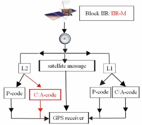
Then, in the Figure 2.5., let us see how the complex satellite signals broadcasted by the satellites can be described.
Figure 2.5. The complex signal structure of NAVSTAR GPS
The fundamental frequency of each satellite atomic clock is 10.23 MHz. Multiplying this fundamental value by 154 and 120, respectively, the two fixed L-band carrier waves are generated, which are known as L1 and L2 (Link 1 and Link 2). This can be given by the following formula:
The wavelengths applied here have a relatively favourable capability for breaking through the atmosphere. Each satellite, basically, generates the same two carriers, which then are modulated by PRN codes. One goal of binary coding is to measure the travel time; that is to say, it serves for transmission of satellite clock signals to the receiver (using C/A and P-codes). The other goal is to transmit the user the navigation message, also called the Data-code, which is essential to positioning. Each satellite has codes of its own; however, the carrier frequencies are the same.
This is just inversely true for GLONASS satellites, where the codes are the same and unique frequencies are connected to the satellites.
The civil C/A-code (C1 or C2 on the R-M type satellites as well) is repeated once every 1 millisecond (300 km), and this means nearly 80 digital series, taking the satellite-receiver distance into account. If this code is used for range measurement then its accuracy is about 3 m, considering 1% of the effective wavelength approximately 300 m, but it could be much better in a favourable case.
The other code is the P-code (P1 and P2), providing more accurate range measurement compared to the previous civil code, the total length of which is 38 weeks, with a one-week segment assigned to each satellite. In general, it is called the military code. The P-code (in an encrypted form Y-code) is enabled to provide a result for users improved by one order of magnitude over the C/A code, that is, its chip length is 30 m and its accuracy is 1% of it, consequently it is 30 cm. Earlier the P-code receivers were only used in the NATO armies so their application was not possible in Hungary.
The 30-second-long navigation message consists of 5 subframes (of 6 seconds each). The content of these are as follows: clock data, corrections (first subframe); orbit data and corrections (second subframe); orbit data and corrections (third subframe); other messages, UTC, information on the ionosphere (forth subframe); almanac data (fifth subframe).
The control segment, considering the base task of GPS, performs a so-called inverse positioning – that is to say, it determines orbit data (ephemerides of the satellite) using the observation data from each monitoring station, of which there are two kinds: forecast and post-processed. Most users apply forecast data; post-processed data is only needed for higher-accuracy applications. Five monitor stations belong to the GPS system, located at American military bases in nearly equalized distribution. These are as follows: Colorado Springs (North America), Hawaii (Pacific Ocean), Kwajalein (North Pacific Ocean), Diego Garcia (Indian Ocean), Ascension Islands (Atlantic Ocean). In addition to the enrolled monitoring stations there is a Master Control Station (MCS) in Colorado Springs where tracking data from the monitor stations are processed. Each monitor station sends its collected data to process (satellite-receiver distances, meteorological and ionosphere data) to MCS, among whose tasks can be found orbit calculation, examination of satellite clock parameters and computation of global ionosphere parameters. The processed data from here are sent back to three so-called ‘injection’ stations (Kwajalein, Diego Garcia, Ascension) where they are uploaded by ground antennae to each GPS satellite. As far as data update is concerned, its frequency has been reduced due to introducing newer and newer satellites to the system. This service without contact was 8 hours for Block I type, once a day for Block II and IIA and once every three months for Block IIR satellites. In Figure 2.6 the location of monitor stations along the Equator can be seen.
Figure 2.6. Arrangement of terrestrial monitor stations [ii ]
It is noted here that besides the ‘system manager’ other organizations also deal with tracking of satellites and determining precise orbital data. One of them, for example, is the Cooperative International GPS Network (CIGNET).
The user segment consists of an operator – or a well-trained user when complicated tasks are to be solved – and various satellite receivers. This is shown in Figure 2.7.
Figure 2.7. GIS data capture with GPS technique
We do not want to deal with the user himself/herself. It can be stated, however, that learning special knowledge related to the application of GPS technique – as a function of tasks to be solved – can be really different in terms of the time involved. In the case of a simple navigation receiver, this time may be some hours if the person in question learns only how to handle the GPS receiver. However, studying something like professional post-processing software thoroughly may require one year or so from a GPS researcher.
A great variety of GPS receivers are available for the user in the comprehensive application of the GPS technique. In Figure 2.8 some of them are illustrated as well.
Figure 2.8. GIS and geodetic GPS receivers
Satellite receivers can be divided into groups according to various points of view. Considering these, let us look at a few of them.
1. according to the number of reception frequencies:
single frequency (L1) or double frequency (L1 and L2), 2. on the basis of the number of reception channels:
4, 6, 9, 12, 24, 48, 72,
3. to the number of ranges to be measured by the receiver:
C1, P1, 1, C2, P2, 2,
4. on the basis of the fundamental systems to be observed by the receiver:
GPS, GPS+GLONASS, G3 (+Galileo), Compass, 5. according to application/accuracy/price:
navigation receivers (5-15 m) (50,000-200.000 HUF), GIS receivers (cm) (1-1.5 million Hungarian forint), geodetic GPS receivers (cm)
single frequency (1-2 million Hungarian forint), double frequency (2-4 million Hungarian forint), RTK (single frequency or double one) (3-7 million HUF), 6. on the basis of application:
hand-operated GPS receivers, (on foot) surveying systems, static surveying systems, built-in GPS sensors.
Introduction of the GLONASS satellite fundamental system
The Russian GLONASS is also a first-generation satellite fundamental system, with a history full of ups and downs, and compared to the American GPS now it is undergoing a modernization process. The system was originally devoted to military purposes, and perhaps we can say it has been operating "at half power" since its short first realization. As GLONASS is less known compared to GPS, now it is discussed in more detail.
Parallel with a Russian name an acronym of the English name "GLObal NAvigation Satellite System" gives the well- known shortening for the global satellite navigation system development which the Soviet Union started in the second part of the 1970s. In contrast with GPS, there was little information about GLONASS earlier, which must have been connected with the primary navigation application of this system. In 1988, however, with the rise of such new political
slogans such as "publicity", the Soviet Union started to spread service information outward gradually, and then offered GLONASS for international use. As a result of this, an agreement was concluded between the USSR and the USA in which the concerned parties declared their intention of joint use of the two satellite systems in civil aviation on the one hand, while on the other hand they promoted developing integrated receivers capable of combined use of both satellite configurations. After 1995 the first GPS+GLONASS receivers appeared on the market.
The first GLONASS launch was on November 12, 1982, nearly four years after the first GPS satellite was put into orbit.
As a result of further launches, the first satellites were followed by newer ones, and owing to this in 1993 the first phase of the designed satellite configuration (7 active satellites each on two orbital planes) was developed. Then, in 1995 the second phase (the full 24-satellite configuration) was completed. The space segment realized in January 1996, however, carried with itself the former technical, political and economic difficulties (e.g. short life of the satellites;
ceasing of the Warsaw Treaty; disintegration of the Soviet Union and internal political and economic problems of Russia), effects of which could be seen in GLONASS developments starting years back. The satellites of the ‘96 full configuration – compared to the similar GPS satellites – had a relatively short lifetime, and therefore their number decreased gradually. Replacing them were only 12 satellites from 4 launches between 1998 and 2002. At the end of the year 2002 there were only 7 operating satellites and 4 pre-operating ones in the space segment.
In spite of the unfavourable situation the Russian Government made more positive decisions in the interest of the system in February, 1993, when it took a stand for applying GLONASS for scientific and social-economic purposes while also emphasizing its significance in the defence of Russia. In addition, GLONASS was offered as an international navigation system, hoping for financial promoters for the purpose of future development. In August of 1999 Russia passed a law requiring that each vehicle carrying hazardous load be provided with an on-board GLONASS+GPS receiver. The latter regulation also confirmed the commitment of Russian leadership towards the development and operation of the GLONASS system.
The GLONASS system – similarly to GPS – is destined for both military and civil applications when its system design is completed. The Russian satellite fundamental system, like NAVSTAR GPS, consists of space, control and user segments. Satellite constellation of the space segment includes 24 satellites operating simultaneously according to its plan. GLONASS satellites were put into three orbital planes with an inclination to each other of 110º and equal distribution (considering a 45º latitudinal increment). As far as mutual positions of satellites on the neighbouring orbital planes are concerned, the system designers took a 15º latitudinal increment into account. Studying the launches, a certain time lag can be observed between the launch time and that time when each satellite occupied its position in the orbit (Orbital planes: I, II and III; Positions: 1-8, 9-16, 17-24).
The first GLONASS satellite was launched on October 12, 1982, the subsequent ones in launches occurring twice a year. All the satellites were put into orbit by proton rockets (SL-12) from Baikonur Cosmodrome. Three satellites were launched simultaneously for circular orbits of 200km (there were satellites for testing and laser ranging at initial launches), then they were positioned for a nominal circular orbit of 19,100 km mean altitude with their own positional boosters. The Russian satellite, which is illustrated in Figure 2.9, is 1,400 kg in weight; its average life was 2 years or less in most cases. By the end of 2002, 31 GLONASS launches had taken place; however, two of them were unsuccessful. The Russian put 71 GLONASS satellites into orbit by 1997; and 83 by 2003, but 8 test satellites and 2 Etalon ones used for laser ranging can be included in the whole program. Further details of these launches can be found in Table 2.2.2.4.1.
Figure 2.9. A GLONASS spacecraft [iii]
In spite of the fact that 50 satellites had been launched by the end of 1992 (including the two unsuccessful ones) the number of operating satellites at that time was only 12 due to their short length of life. In comparison to that, it can be mentioned that among the American Block I type satellites there was one which operated for 11 years instead of its 5- year design life.
From January, 1996 the number of satellites in the full configuration decreased rapidly due to the cancellation of the planned launches. In August, 1998 the space segment consisted of only 14 operating satellites and one spare. In addition to that there was one satellite under maintenance. In the next four years it is true that there were four subsequent launches (the last one in December, 2002), however, there operation did not reverse the decreasing trend in terms of the number of satellites. On July 16, 2003 the status of GLONASS constellation was as follows: there were altogether 8 operating satellites. In that year 3 satellites went out of order in the first orbital plane.
The 10 operating satellites were located in the first and third orbital planes (2 and 8 satellites, respectively). The second orbital plane, similarly to its status in 1993, was totally empty. Between 1997 and 2004 there were altogether 5 launches, which meant 15 satellites for the system. As a result of this the satellite constellation consisted of 7 operating satellites at the end of 2002; 8 satellites in June, 2003 and 10 in January, 2006. At that point the first orbital plane was full, the second one was empty and in the third one there were 5 satellites.
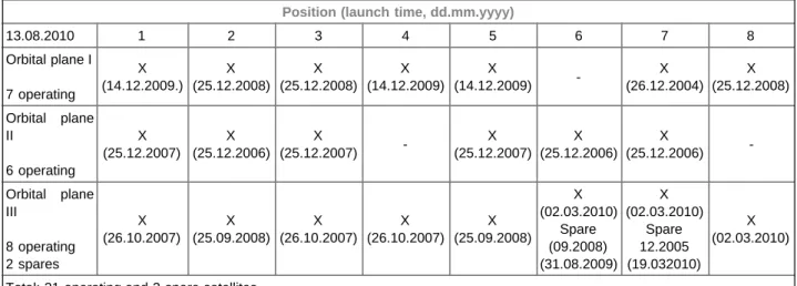
Since then this tendency towards increase has continued, and has also been helped by the appearance of Galileo and competition among the fundamental systems. The satellite configuration of August 13, 2010 is shown in Table 2.3.
Position (launch time, dd.mm.yyyy)
13.08.2010 1 2 3 4 5 6 7 8
Orbital plane I 7 operating
X (14.12.2009.)
X (25.12.2008)
X (25.12.2008)
X (14.12.2009)
X
(14.12.2009) - X
(26.12.2004) X (25.12.2008) Orbital plane
II
6 operating
X (25.12.2007)
X (25.12.2006)
X
(25.12.2007) - X
(25.12.2007) X (25.12.2006)
X
(25.12.2006) - Orbital plane
III
8 operating 2 spares
X (26.10.2007)
X (25.09.2008)
X (26.10.2007)
X (26.10.2007)
X (25.09.2008)
X (02.03.2010)
Spare (09.2008) (31.08.2009)
X (02.03.2010)
Spare 12.2005 (19.032010)
X (02.03.2010)
Total: 21 operating and 2 spare satellites
Table 2.3. GLONASS constellation (August, 2010)
From this table it comes to light that the GLONASS satellite configuration might be full again very soon. The previous M-type satellites were followed by three subsequent ones in space on September 2, 2010, from which two are expected to be placed in the 4th and 8th positions of orbital plane II. At the same time, several satellites will finish their operation in the orbital plane I in the near future. Three subsequent satellites, their replacements, are due to be launched in November, 2010 and the first representative of the modernized new generation K series might appear in orbit as well.
GLONASS, similarly to GPS, means a single-way distance measurement system. Each satellite of the system broadcasts two carriers modulated by codes for civil and military applications. At each satellite the applied carrier frequencies are not constant values but individual carrier frequencies are used which are changed by known values referring to one another. The GLONASS ICD specifies the frequency scheme and the planned changes. On both L- band carriers the equivalent civil and military codes can be found; furthermore, a navigation message of 50 bit/second modulation velocity as well. In the case of GLONASS, therefore, the point is a Frequency Division Multiple Access (FDMA) system, contrasting with GPS, where a Code Division Multiple Access (CDMA) solution is applied. The frequency ratio of GLONASS signals is 9/7 (the detailed introduction of them is also found in Table 2.2.2.4.2). Near frequency domains of GPS and GLONASS enabled to use combined antennas and joint preamplifiers in one receiver.
All the satellites use the PRN codes. Both code frequencies are equal to the halves of the equivalent GPS code frequencies. It is also interesting that in connection of civil applications Selective Availability (SA) causing lower accuracy was not introduced at all. And what is more, in addition to the civil code, a military code is available as well though its use is not recommended by the Russian authorities. The time and frequency value of GLONASS signals is provided by one of the three caesium atomic clocks located on board each satellite, which operates at 5 MHz.
GLONASS system time is compared with UTC (Soviet Union/Russia); GPS time is connected to the American UTC.
Both of these differ from international UTC. This deviation is 10-9 second order of magnitude for GPS, and 10-6 second order of magnitude for GLONASS.
The Master Control Station (MCS) of all the monitor stations is Moscow. The few monitoring and ‘injection’ stations of this global positioning system are all placed in the territory of the former Soviet Union. Because of this, we cannot speak about global coverage connected to monitor stations. The ground control segment is supplemented with further stations for laser ranging. All the monitor stations send their pre-processed data to the MCS for further processing, where orbit and clock data and their corrections are determined. Then the MCS sends back all the computed results to the monitor and ‘injection’ stations so that they should update the on-board data of each satellite.
As far as the user segment is concerned, primarily, we must talk about satellite receivers, but the operator is also included. In the first developing phase of this satellite system, between 1989 and 1995, the production of GLONASS receivers was limited almost to the former USSR. For international practice these receivers were not available, and thereby those were no rivals for GPS receivers. In 1995 the full constellation was developed for a brief time, and shortly before this notable year interest in the system increased. As a result of that, in addition to certain international research institutes, more universities designed and constructed GLONASS ‘prototype’ receivers as well, which were developed to gain experiences for knowing the system better. You can find a conception of a common Russian- American so-called prototype receiver in which the ideas about receivers capable of integrated reception of the signals related to both systems were outlined. The appearance of the single-frequency GPS+GLONASS receiver, GG- Surveyor produced by the company Ashtech can be counted to be a significant result because it was available on the market as well. This GPS tool can be considered to be a pioneer among the receivers capable of receiving the signals of both mentioned satellite systems. The number of the produced GLONASS and combined receivers must be more than 10,000 today, but their number is orders of magnitude lower than the number of operated GPS receivers.
As for the expected future of GLONASS, it seems at present that the Russian Government is continuing to provide the financial budget required to run the GLONASS program. In this project the production and launches of further GLONASS-M and GLONASS-K satellites (with about 7- and 10-year design lives, respectively) are also included.
From the new modernized system a multiple increase in accuracy is expected, while a reduction in launch costs is also a goal to be reached by decreasing the size of satellites. A second civil code is available for M code satellites now and the appearance of a second civil frequency (L5) in case of the future K type satellites is also among the plans.
Now, as a summary, in A, B and C parts of Table 2.4. let us compare the technical data of GLONASS and NAVSTAR GPS satellite fundamental systems.
Part A
PARAMETERS GLONASS NAVSTAR-GPS
subsystem of satellites number of satellites 21+3 (completed January, 1996)
21+1 spare (July, 1997) 14+1 renov. +1 spare (08.1998) 7+4 before operation (12.2002) 8 operating (07.2003)
10 operating (05.2004) 13 operating (01.2006) 21 operating (08.2010)
21+3 28 (02.2003) 31 (05.2004) 29 (03.2006)
31 operating (08.2010)
number of orbital planes, number of satellites,
chronology of satellite launches
Block I: 10 satellites (1982-1985), average life: 14 months.
Block IIa: 6 satellites (1985-86), average life: 17 months.
Block IIb:6(+6) sats. (1987-88), two unsuccessful launches (+6), average life: 22 months.
Block IIv: 31satellites (1988-95), Phase 1: 10(+2) sats (1988-90), 2 geodetic reference satellites (+2), Phase 2: 24 satellites. (by 1995).
Further launches: 9 sats. (1995);
12 satellites (1998-2002);
9 satellites (2003-2005).
Block I: 11 satellites (1978-1985), design life: 4.5 years,
(4 operating ones even in 1993).
Block II: (1989-98), full configuration, (introduction of SA and A-S),
design life: 7.5 years.
Block IIA: (1990-1997),
some of them with retro-reflectors.
Block IIR: (1997-2004),
10-year design life, improved communication capability.
Block IIR-M: (from 2005), improved signal structure with C/A-code on L2 as well (L2c),
new military M-code,
GLONASS-M satellites design life: 5- 7 years,
new civil code (L2c)
GLONASS-K satellites (first launches expected in 2011),
(introduction of L5 frequency).
higher accuracy, improved capacity.
Block IIF: (2010-2019), 33 satellites, 11-year design life, (L5),
sophisticated signals, Block III: (from about 2013), under design at present,
32 satellites, 16 (by 2016) and 16 (by 2019),
M-code control, DGPS.
average altitude 19130 km 20180 km
inclination 64,8° 55°
orbital periodic time 11 hours 15 minutes 11 hours 58 minutes orbital parameters 9 parameters
(position, velocity, acceleration in ECEF perpendicular system)
Keplerian orbital parameters and interpolation coefficients
geodetic system Earlier: SGS 85 (Soviet Geodetic System),
At present: PZ-90.
WGS 84 (World Geodetic System)
system time GLONASS system time, UTC (SU),
caesium atomic clocks
GPS system time, UTC (USNO) caesium, rubidium atomic clocks duration of navigation message 2.5 minutes (navigation main frame).
A main frame consists of 5 frames lasting 30 seconds each.
One frame includes 15 lines (sub- frame).
Duration of a line (binary series) is 2 seconds.
12.5 minutes (One main unit includes 25 units. One unit consists of 5 sub- units and its transmission time is 30 seconds. One sub-unit consists of 10 words and its duration is 6 seconds. A word makes 30 bits and it takes 0.6 seconds). The complete navigation message includes 1500 bits (one unit).
signals Fundamental frequency:
5 MHz
Original: until around 1993 L1: 1602 + k x 0.5625 /MHz/, L2: 1246 + k x 0.4375 /MHz/, k = 0, 1, 2,..., 24 /0®/ testing /.
Modification: 1993-1998 k = 0, 1, ...,12, 22, 23, 24 possible new satellites:
k = -7® -1.
1998-2005 ® k = -7, ..., 12, after 2005 ® k = -7,..., 4, (5, 6 for testing only).
Fundamental frequency: 10.23 MHz L1: 1575.42 MHz
(*19.03 cm) L2: 1227.60 MHz (*24.42 cm)
two new civil frequencies:
L2: +C/A code, 12 satellites L5:1176.45 MHz (from 2010) 12 new satellites,
new ME military codes on L1 and L2
codes the same codes for all the satellites
L1: C/A-code and P-code L2: P-code
C/A-code (M type satellites)
different codes for each satellite L1: C/A-code and P-code L2: P-code
C/A code (RM type satellites)
Part B
Control Segment continuous observation and
control
Moscow and a network of tracking stations spread out across Russia, uploads: twice a day.
one Master Control Station (Colorado Springs) and four further control stations (Kwajalein, Ascension, Diego
Garcia, Hawaii)
Controlling the system times Moscow Colorado Springs
Transformation parameters between WGS 84 and PZ 90:
1. Rossbach et al. (German Geodetic Institute) dual-frequency GPS/GLONASS receivers, data of six tracking stations in Europe:
(a rotation around the z axis was found statistically significant)
2. Pratap Misra et al. (Lincoln Laboratory, Lexington) a former transformation formula between SGS 85 and WGS 84:
(They used two GLONASS satellites expressed in both systems.)
(An offset of the origin along the axis y and a rotation around the axis z were statistically significant.)
Part C
User Segment
receivers - GLONASS receivers in the former
USSR (design bureaus and manufacturing plants in Russia, Ukraine, Belarus).
- First generation receivers:
Large, heavy units with 2-4 channels.
- Second generation receivers:
digital signal processing, lighter and more compact receivers,
Shkiper-N receiver (digital signal processing, 5,6,12 channels),
- for civil application: dual GPS/
GLONASS capability,
- a receiver of geodetic accuracy:
REPER (6 channels., L1, 5 kg) -prototype receivers capable of receiving the signals of both systems.
- manufacturing GPS and GLONASS receivers for the market:
Ashtech GG Surveyor
(single frequency, observing 48 satellites).
- Some important manufacturers of combined receivers:
GPS-receivers (antenna + RF unit) - a wide range of receivers not only for military but also civil use
Types:
-navigation (C/A-code receivers, -military (P-code),
-GIS receivers,
-geodetic ones (combining carrier phases and codes):
-L1, C/A-code, L2,
-L1, C/A-code, L2 P-code or
Y-code instead of P-code when A-S is valid,
(encryption of P-code).
- RTK receivers (single- and double frequency)
-official cancellation of S/A on May 2, 2000,
-appearance of new civil and military codes,
-introduction of a second civil carrier
former SU companies; ’NAVIS’
Design Bureau
(Moscow); Company KOTLIN (Saint Petersburg); Ashtech, 3S Navigation (USA), Daimler-Benz, Aerospace, JAVAD Positioning Systems
-Latest producers of combined receivers today:
Topcon/Sokkia, Trimble, Leica GNSS geodetic receivers!
e.g. Topcon GR3, Leica Viva GS10 or Trimble R4 GNSS receivers.pl.
Topcon GR3, Leica Viva GS10 vagy Trimble R4 GNSS vevők
(L5) is expected.
- GNSS receivers on the market!
Table 2.4 Features of GLONASS and NAVSTAR-GPS
Characteristics of Galileo satellite fundamental system
Galileo is the first global satellite positioning and navigation system to be developed by the European Union (EU) and European Space Agency (ESA) for special civil goals in the frame of a joint venture. When introducing Galileo it is necessary to emphasize that we are going to review a modern future system, since the realization process is still at the beginning. Perhaps you can say that this European initiative will result in a very modern so-called second- generation fundamental system after its completion, thereby stimulating the present operating co-systems with healthy competition even in its developing phase. This competition is reflected well in the modernization process of the mentioned co- systems. From the technical independence of present operating systems (e.g. the American GPS) the community of users can benefit from the abundant supply. Naturally, each research and development group will enjoy mutual advantages of cooperation. Satellite global positioning systems play an indisputable role in routine life even today, and their effect on social and industrial development will be become even more decisive. It does not require any special foresight to predict that radio navigation will be one of the most important parts of future control systems. There are a number of sectors (e.g. traffic) which depend on this technique even today, when the range of possibilities is still utilized only in part. Certain analysts compare satellite navigation to the importance of the wristwatch, an earlier invention, laying emphasis on their opinion that nobody will be able to live without knowing their accurate position and time. This is why the European Union considers it important to have control of its own independent satellite configuration. It does not want to depend on systems and technologies which were originally developed for military purposes and for applications outside Europe.
The Galileo program is of strategic importance for Europe, since it will result in similar revolutionary changes as happened with mobile phones in the recent past, causing the development of a new generation of services. In road and rail traffic, for example, it will enable us to predict travel times. Automatic vehicle control systems will help to decrease the number of traffic jams and accidents. Though various aerial, maritime and land traffic forms are mentioned most frequently in connection with its advantages, its use in areas such as agriculture, fishing, construction, national and civil defence, rescue and life-saving services and telecommunication cannot be neglected. The special on-board characteristics of Galileo satellites will provide new service categories such as traffic, commercial or improved research and rescue functions. In critical applications (e.g. civil aviation, navigation of vehicles transporting hazardous materials, etc.) Galileo and NAVSTAR GPS mean two systems having independent signal sources; thus it could be possible to substitute satellite-based positioning and time measurement for the conventional infrastructure of today.
When the Galileo system was designed the following aspects were considered: minimization of development and operation costs; user and market demands and trends, and the possibility of joint operation with present working fundamental systems, primarily with the American GPS. As far as the costs are concerned, they are about 3.2-3.4 billion Euro, which sum should provide for the launches of satellites and construction of a ground service system. The investment cost is roughly comparable to other European projects and can be compared to the cost of the finished Heathrow Airport Terminal 5 or a modern motorway of 150-km length. The two primary cost bearers of the Galileo project are the EU and ESA, but investments from the private sector are also expected.
The space segment of Galileo is planned to consist of 30 satellites deployed in three Mean Earth Orbits. The inclination of orbital planes to the Equator is 56º, and there will be 9 satellites and a spare one in each plane (Figure 2.10). This satellite constellation will provide better coverage on locations of higher geographical latitude – thus in the northern part of Europe – than it is realized with American GPS satellites today. The mean rotation altitude of satellites is 23,616 km; the orbital periodic time is 14 hours; their weight is 650 kg and their design life will reach 20 years. On board each satellite two atomic clocks will provide the necessary frequency etalon. One of them will be a rubidium
clock, the other one a hydrogen maser clock. These clocks are made in Europe and are being tested on board the first pilot satellites. The Galileo system time will be adjusted to the International Atomic Time. The contracts for producing the first two test satellites were signed in 2003, and they have been put in orbit since then. The task of one of the pilot satellites is to broadcast Galileo signals from a designed orbit position to test the reserved frequencies. The other satellite is used for minimizing the risk of an unsuccessful launch and representing the equipped technology. Galileo satellites will transmit ten different signals on the following four L-band frequencies: 1176.45 MHz, 1207.14 MHz, 1278.75 MHz and 1572.42 MHz. As can be seen, the frequencies of two Galileo signals are equal to the L1 and L5 frequencies in American GPS system (the L5 signal is connected to only new F type satellites). The service provided by Galileo signals can be divided into two levels: basic level and selective availability. The basic level will be without charge here as well, similarly to the American GPS, but the system operators promise more reliable service for general user applications. To use the other value-added commercial and professional level, naturally, it will be necessary to pay, and it will be available only to authorized users. Consequently, these users have to be provided with excellent operation. The level of selective availability should be so high in the case of certain users that service jamming should happen not at all. The income from service will mean a significant contribution to the cost-effectiveness of this system.
The ground service infrastructure of Galileo system and its sub-system of monitor stations will widen with an integrity- monitoring infrastructure separated from the afore-mentioned sub-system. The main tasks of the subsystem of monitor stations will be to observe the satellite constellation continuously – that is, to determine each satellite’s orbit – to provide time synchronization and to produce navigation messages. All of these are provided by establishing and operating 15 automatic monitor stations, a control centre and 4 telemetric stations. An independent monitoring system consisting of a European integrity centre and 3 radio stations will be responsible for system integrity. Integrity capability of the system is a key issue for navigation applications. Each user, however, should receive a warning within a few minutes when the satellite system (or certain satellites within it) is out of order (fact and time) and their accuracy numbers. The lack of this very important service is why the American GPS system can not be used within full limits in such critical navigation fields such as civil aviation control. The sub-system of monitor stations will establish suitable connections (interfaces) with the various service centres to provide value-added global commercial, rescue and life- saving services. Another innovation is that transceivers compatible with the Cospas–Sarsat system will be installed in Galileo satellites, which will increase present positioning accuracy by several orders of magnitude compared to current systems. In addition, the L-band transmitters would be suitable for a person in trouble to receive confirmation about that his/her signals had been received and a life-saving mission was underway.
The most important element of the user system is the receiver itself. We have already talked about the compatibility of Galileo with the American GPS system. It is also known that so-called GPS+GLONASS receivers were/are made for receiving the signals of American and Russian satellite systems in spite of larger differences than those between Galileo and GPS. It is also obvious that the increased number of satellites coming from joint use of fundamental systems results in a number of advantages when the various observation methods are applied. In relation to this we can mention applications in covered territories (towns, canyons, forested areas, parking spaces); more effective resolution of phase-ambiguity; an increase in the number of frequencies available for the system, etc. From this it follows that potential producers, when designing Galileo receivers, are thinking of combined receivers which will be able to receive the transmitted signals of all three fundamental systems. It also means that new processing programmes will be needed as well. It is also not difficult to predict that the modernization process of each fundamental system will lead to increasing demand for receivers, including combined receivers – a trend which has been confirmed by the market in recent years.
In addition to the applications that are well known among users a number of value-added services will be offered by Galileo. As was mentioned earlier, application fields will cover, among others, traffic (road, rail, aviation, maritime) and the transport of goods; energetics; telecommunications; agriculture; fishing; environmental protection; the construction industry; recreation activities; national defence; civil defence; tasks related to safety and private defence and finally, such kind of special fields such as mining.
Figure 2.10. Constellation of Galileo satellites, and a picture of a satellite [iv]
As far as the present situation connected to the development of Galileo is concerned, let us mention some matters.
With reference to this system, it is well known that it is in Initial Test Operation Phase. Its part is to model the designed orbit; to form navigation message and to test the on-board clocks. The two test satellites launched until now to perform these tasks are GIOVE-A and GIOVE-B. A brief life story and the mission of the test satellites are as follows:
In the morning of December 28, 2005 the first test satellite, GIOVE-A, was launched successfully according to schedule with a Soyuz-Fregat booster, and put into its final orbit. The first test satellite was observed by the ground control staff at the expected time. A test run of the on-board equipment and the laying out of both satellite solar panels occurred as planned, thus GIOVE-A started its planned mission. The mission of this satellite is to test Galileo navigation signals and both on-board rubidium atomic clocks. A further task of this satellite is to examine the radiation along its space orbit, the height of which is 23,258 km and whose inclination is 56º to the Equator.
On April 27, 2008 – with a significant delay compared to the planned point of time – the Russians put GIOVE-B in orbit. The primary task of this satellite is to test frequency etalons, the passive hydrogen maser clock which can provide more precise positioning and is designed for installation in the final satellites. In the meantime, due to the delay in the launch of this satellite, an order was given the producer of GIOVE-A for a new satellite.
Putting additional satellites in orbit, which can provide true service, has without a doubt been delayed by the current economic crisis. It was considered as a significant step forward, however, that the Septentrio Company developed the first Galileo receiver card. The Belgian Septentrio is an active participant in the Galileo program, and this company runs several research and development projects continuously at Galileo Joint Undertaking (GJU) and European Satellite Agency (ESA). According to this Septentrio will be able to offer the best Galileo receivers in commercial circulation very soon.
The Galileo concession company, led by Alcatel Espace, agreed with EU about the most important ground locations of this system. As a result of this agreement the Centre of Concession Owner will be planned in Toulouse (France), however the Operation Centre will be established in London (Great Britain). The Constellation Control Centre (CCC) and one of the Performance Evaluation Centres (PEC) will be built in Germany. The other PEC and the Mission Control Centre (MCC) will be installed in Italy. In Spain, an essential establishment, a Second Control Centre, will be developed for critical applications being important from the aspect of life and property safety such as commercial shipping and public aviation). When primary control centres (CCC, MCC) are operated in perfect order this station will be the venue for further education of the staffs of MCC and CCC and for testing new hardware, software and processes.
The Chinese Compass regional/global positioning system
In China a demand for developing of a regional satellite navigation system had already appeared in the 1980s. The idea was a so-called twin satellite system, where two geostationary satellites were imagined to be signal sources.
Distance measurement was planned to be solved on the known principle of double-way ranging. The Beidou-1 system suited this idea, both pilot satellites of which were put into orbit in 2000. A segment of Beidou-1 was a few ground control stations which took part in positioning in an active way. The point of measurement was to observe the continuous signal transmission of the mentioned satellites with an active receiver of a user, then to send them back to the satellites, which transmitted the signals to one of the ground control stations, where they were evaluated. The travel time was measured by the satellite clocks precisely and the clock error was eliminated by the double-way measurement. Knowing the travel time, it was possible to calculate the satellite–receiver distance. Considering the distance between the two satellites and an approximate vertical coordinate referring to the measuring point, the ground control station was able to determine a preliminary position. This was refined on the basis of a digital terrain model (DTM) of high accuracy, then the corrected position was applied to the next measurement. Thanks to this iteration technique, positioning accuracy in the horizontal sense was about.
20 m, which approximated the accuracy of absolute NAVSTAR-GPS positioning. To use Beidou-1 it was necessary to observe both geostationary satellites at the same time. This regional system was operated just for about 5 years and it was able to service more than 100 users simultaneously. The main goal of application, of course, was the military one, but the system was used for other tasks as well, mainly rescue missions.
In the middle of the first decade of the 21st century China started to develop a new second-generation satellite positioning system that is designed to be realized first in regional form (China and its region), then in global form (extended for the Earth). The name of this system is COMPASS, which is the name used here from now on, although an accepted practice is to term COMPASS Beidou-2. COMPASS is a system under development. According to the plans the future fundamental system would consist of 35 satellites, from which 5 rotate in geostationary orbit (hereafter GEO); 3 in inclined geostationary orbit (IGSO) and 27 in a so-called middle-earth orbit (hereafter MEO). The MEO satellites move in orbits having an altitude of about 21,000 km and an inclination of 55 degrees. Their rotation time is 12 hours. The first herald of COMPASS system was a MEO satellite launched on April 14, 2007. After all this information, let us survey in Table 2.5 what the actual satellite constellation is like.
The Beidou-2 satellites are more robust than their predecessors were. The three frequencies used by COMPASS satellites overlap the frequencies of the Galileo satellites.
The first phase of COMPASS (the Chinese regional system), which would consist of 14 satellites, `is planned to be finished by 2012. After that the Chinese Navigation Satellite System (CNSS) would be realized. The cost of this system can be estimated at several billion American dollars.
The CNSS system will be fully similar to the other formerly described fundamental systems in that one-way ranging will be used for positioning the location of a ground receiver. The accuracy of an autonomous survey will be about 10 m.
BEIDOU-1 1A October 30, 2000 GSO
1B December 20, 2000 GSO
1C May 24, 2003 GSO
1D February 2, 2007 GSO
BEIDOU-2 COMPASS
Compass-M1 April 13, 2007 MEO
Compass-G1 April 14, 2009 GSO
Compass-G2 January 16, 2010 GSO
Compass-G3 June 2, 2010 GSO
Compass-IG1 August 1, 2010 IGSO
Compass-G4 October 31, 2010. GSO
Compass-IG2 December 17, 2010 IGSO
Table 2.5. Satellites of Beidou-1 and Beidou-2 systems
Satellite-Based Augmentation Systems (SBAS), EGNOS and WAAS
The acronym EGNOS (European Geostationary Navigation Overlay System) covers a satellite-based augmentation system which is often mentioned as a predecessor to Galileo. The point is about a development based on GPS and GLONASS fundamental systems that enables a wide range of users to be served (civil aviation, maritime shipping, road transport, etc.). The task of this system is to provide users with correction data in the European geographic region and its near environment, thereby decreasing the horizontal accuracy to below 5 m compared to the accuracy of 7-15 m for absolute GPS positioning. Among the various users, considering integrity, accuracy, availability and service continuity, the requirements of civil aviation are the most rigorous. As a result of this, the operation goals of EGNOS are determined by the requirements in civil aviation, covering the high demands of ground and maritime users which appear in these fields.
The EGNOS system consists of three geostationary satellites: the AOR-E (PRN120; 15.5 W) is in the west over the Atlantic Ocean; the IOR-W (PRN131; 65.5 E) is in the east over the Indian Ocean – both of them are Inmarsat satellites – and the Artemis (PRN124; 21.5 E) is a communications satellite (ESA is its owner).
The EGNOS ground sub-system consists of 34 GNSS (GPS, GLONASS, GEO) Ranging and Integrity Monitoring Stations (RIMS); 4 Mission Control Centres (MCC) and 6 Navigation Land Earth Stations (NLES). In addition to that a part of the ground system is the EGNOS Wide Area Network (EWAN), which connects the components of the control segment.
The network of RIMS observes NAVSTAR and GLONASS satellites continuously. The measured data is sent to Mission Control Centres (MCC). These perform the determination of differential corrections (WAD) and integrity data, and then the computed corrections are relayed to the so-called injection stations (NLES) via the communication network (EWAN). After that these valuable corrections are uploaded to three geostationary satellites. Then these satellites broadcast their signals to all the users on the GPS L1 frequency. Having received the corrected signals, GPS receivers are able to increase the accuracy of measurements. In the majority of services, each user receives a real image about the quality of correction signals and any possible failure of satellites within a few minutes. Today several dealers offer such receivers, which are capable of processing both European EGNOS and American WAAS.
From February 2000 to May 2005 the real-time prototype of the EGNOS system, the so-called EGNOS System Test Bed (ESTB), was in operation. The development of ESTB served several goals. These were as follows: promotion of EGNOS design; demonstration of system capabilities for potential users, and studying future EGNOS developments.
From June 2005 the operation of EGNOS started its Initial Operation Phase (IOP). From the beginning of this period of time it was coordinated by European Satellite Service Provider (ESSP). The initial phase was an 18-month period of time with a goal of operating, stabilizing and assessing the system step by step. Broadcasting the EGNOS signal was performed with three satellites at that time. These were: Artemis (PRN124); IOR-W (PRN126) temporally and AOR-E (PRN120), which transmitted ESTB signals. The open-user service was introduced from the first quarter of 2006. In this phase reliable service was yet not guaranteed. The expected accuracy of positioning was less than 2 m in horizontal sense and much better than 4 m in vertical sense in most cases.
In the last operational phase (Continuous Operations), from the beginning of 2007, the system became capable of providing Safety of Life (SoL) services as well. EGNOS is currently in full operation, and ESSP guides and controls all the daily services routinely. It also takes responsibility for operation since it is necessary to demonstrate the service quality to users and concerned authorities.
Parallel to its operation it is also essential for EGNOS to react to the dynamically developing GNSS environment. This includes the Galileo program and the modernization of NAVSTAR GPS and GLONASS (launches of new satellites, L2c and L5).
Reacting to this, a so-called evolution plan was made which dealt with developing additional infrastructure for a European augmentation system on the one hand,and on the other hand prepared EGNOS for receiving L5 signal (installation of GPS L1/L5/Galileo receivers and the renewable transformation of the GLONASS system as well).
As far as the Wide Area Augmentation System (WAAS) is concerned – which is a counter-system connected to the North-American continent – we can say about it that it preceded EGNOS in time and in addition to that this system is also undergoing a modernization process at present. The point is that a satellite-based augmentation system that was exclusively developed for civil aviation. The service of WAAS covers all classes of aircrafts and all flying operations – including on- the-way navigation, departure from the airport and arrival at the airport – providing users with the necessary data and other demands. Among them, precise landing can be mentioned as an example that is provided in the entire territory of the USA, even under unfavourable weather conditions.
The ground sub-system of WAAS consists of 26 Wide-area Reference Stations (WRS); 2 Wide-area Master Stations and 4 up-loading Ground Earth Stations (GES). The reference network performs the observation of GPS signals.
These stations collect and process GPS information and send them to the master stations (WMS). These stations are located in the continental territory of the USA as well asin Hawaii, Puerto Rico, Alaska, Canada and Mexico. Master
stations create the WAAS correction messages, which are sent to the GES stations to be uploaded to the satellites in question. The space constellation of the WAAS system consists of two geostationary satellites which rotate above the eastern and western coasts of USA.
The navigational or correction message is broadcast on a signal similar to a GPS signal. The correction itself involves two kinds of sets: corrected GPS parameters (position, clock, etc.) which are independent of the user’s position, and ionosphere parameters which are specific data arranged in a network system. In addition, the integrity level of WAAS was designed so that it should meet the strictest safety requirements, since it calls the user’s attention to a possible failure of the system in only 6 seconds.
The WAAS system has been operating since August 24, 2000, and the Safety-of Life service has also been provided since July 10, 2003. Its SoL system surpasses that of EGNOS. Preparation of this system is going on in the dynamically developing GNSS environment, mainly with the modernization of the NAVSTAR-GPS system (a new civil code, L5, etc.). In addition, the WAAS system has been expanded by two newer geostationary satellites. On September 9, 2005 the Telesat Anik FIR satellite was launched, which also broadcasts WAAS signals. Not much later, on October 13, the PanAmSat Galaxy 15 satellite was launched, which also provides WAAS signals to users having suitable receivers. While WAAS is mainly designed for aviation use, the system also promotes a number of other applications in agriculture, geodesy, road transport, etc.
It is worth noting here that among the satellite-based augmentation systems the Japanese MSAS and Indian GAGAN must be mentioned as well. The currently existing and developing regional systems together will be able to solve global navigational tasks covering the whole Earth. This has perhaps the greatest significance in air and maritime transport.
3. P
RINCIPLE BEHINDSATELLITEPOSITIONING(GPS)
The primary goal of satellite positioning is to determine the phase centre coordinates (geocentric or local) of a receiver antenna by a kind of surveying procedure. For this, it is necessary to measure ranges among the receiver set up above an unknown point and satellites to be observed over it, to know error sources and other factors influencing range measurements and to consider satellite geometry in addition to a number of other types of information (e.g., surveying methods, reference data, etc.). In Figure 2.11 the principle of satellite positioning is illustrated. When the vectors of this figure are examined it can be stated that can not be determined in a direct way, only its absolute value can be measured. Knowing only just one satellite-receiver distance, however, you can be anywhere in space. If two satellites are observed then our receiver can be located on an intersection curve of two spheres. If our receiver enables us to measure a third satellite as well, then the joint intersection of three spheres gives only two points from which – knowing the spherical radius of the Earth – our true position can be selected.
Figure 2.11. Principle behind GPS
Considering that the coordinates of only one receiver are determined by means of satellites over it and correction data are not applied for increasing the accuracy of the result, this surveying procedure is called absolute GPS positioning.
ANIMATION
2.1. GPS positioning
Absolute static and absolute kinematic surveying methods are distinguished depending on whether the observing receiver is in a stationary position or in movement. In the first case we are eager to know point positions, in the second case, however, path of movement is important. The result of absolute GPS positioning (autonomous surveying) gives the coordinates of point V. The surveying procedure is none other than a spatial resection by ranges. It is also obvious that the accuracy of point V is influenced by two factors, one of them being the accuracy of observed ranges and the other the geometric configuration effect on trigonometric calculations. In the present case this can be described by the geometric factor (DOP-values).
Next let us examine the influence of GPS range observations and the role of satellite geometry on the positional accuracy of a measured point.
Error sources of GPS distance measurement
It is known that when performing any surveying procedure such as the application of the Global Positioning System (GPS), survey results are influenced by various measuring errors. Geodetic field surveying errors – according to their character – are classified into three basic types. These are coarse, regular and random errors. Coarse errors falsify survey results to a significant degree, and they are consequences of human fallibility. Their elimination is possible by accurate survey planning (proper surveying procedure, independent checking). Regular errors have a constant effect on the repeated surveys and therefore they can not be filtered out by repeated measurements. The terminology of model errors is often used for them, since their existence is in strong connection with the selection of a functional mathematical model fitting the actual task and representing physical reality. Random errors always influence survey results, and when conducting measurements (according to statistical interpretation) they reflect the variability of repeated surveys. Figure 2.12 shows the spatial positional instability of a ground point measured by GPS absolute positioning as a consequence of the various types and combinations of error classified here.
Figure 2.12. A Spatial instability of a measured ground point
Coming to the error sources of GPS distance measurement, we can state that it is practical to classify the errors on the basis of the location of appearance. According to this we can speak about errors associated with (1) a satellite, (2) the atmosphere and (3) a receiver and its environment. This can be seen in Figure 2.13.
Figure 2.13. Errors in GPS ranging and locations of their appearance
Considering the size requirements of our book, it is not possible for us to describe each error in the previous groups in detail. Among them only those are selected as examples which influence absolute GPS positioning most significantly.
Let us start the introduction with orbital errors. It is known that they derive from modelling the various physical phenomena imperfectly. The Keplerian orbit of a satellite is not realized in practice since there are a number of external effects (e.g. the attraction of the Sun and Moon, radiation pressure of the Sun, etc.) causing perturbations in satellite orbit. The instability of orbital elements due to the above reasons, determination and temporary updating of orbital data is the task of control stations operating continuously. As a result of this, the transmitted ephemerides from a satellite to a user are always based on previous observations when measurements are conducted. As a consequence, when a user performs GPS surveys the accuracy of the so-called pre-processed orbital data is a function of the actual modelling quality. It is also generally known that so-called post-processed orbital data can be obtained, which is provided by a global monitoring network (e.g. geodynamical: CIGNET, IGS) established for a peculiar purpose for those who need these data for their work. These may be obtainable by Internet as well. Let us finish the problem field of orbital errors with some interesting data. On the basis of actual orbital data the computed positional accuracy of satellites is about 10-15 m, but it will not be more accurate than 3-5 m according to the most optimistic estimations.
As far as clock errors are concerned, you can say that they would not be in an ideal case that is to say when the atomic clocks of a satellite and the quartz clock of a receiver would be synchronized with each other. We know it is not so because precise atomic clocks of satellites also deviate from the GPS system time (about 10-14 seconds/day) due to various relativistic effects, and a receiver has only a "worthless" quartz clock. It was discussed earlier that the control segment also includes clock corrections in navigation message. Here it is also mentioned that the hydrogen maser atomic clocks designed for the latest satellites have better frequency stability than the rubidium and caesium atomic clocks operating at present.


![Figure 2.4. Block II -R type satellite [i]](https://thumb-eu.123doks.com/thumbv2/9dokorg/1138796.81219/6.892.232.679.64.518/figure-block-type-satellite.webp)
![Figure 2.6. Arrangement of terrestrial monitor stations [ii ]](https://thumb-eu.123doks.com/thumbv2/9dokorg/1138796.81219/9.892.171.734.67.342/figure-arrangement-terrestrial-monitor-stations-ii.webp)

![Figure 2.9. A GLONASS spacecraft [iii]](https://thumb-eu.123doks.com/thumbv2/9dokorg/1138796.81219/11.892.197.712.849.1158/figure-a-glonass-spacecraft-iii.webp)