1
(Word count: 5488) 1
Evaluation of a membrane permeation system for biogas upgrading using model 2
and real gaseous mixtures: The effect of operating conditions on separation 3
behaviour, methane recovery and process stability 4
5
Nándor Nemestóthy1, Péter Bakonyi1,*, Eszter Szentgyörgyi1, Gopalakrishnan
6
Kumar2, Dinh Duc Nguyen3, Soon Woong Chang3, Sang-Hyoun Kim2, Katalin
7
Bélafi-Bakó1
8
9
1Research Institute of Bioengineering, Membrane Technology and Energetics,
10
University of Pannonia, Egyetem u. 10, 8200 Veszprém, Hungary
11
2School of Civil and Environmental Engineering, Yonsei University, Seoul 38722,
12
Republic of Korea
13
3Department of Environmental Energy Engineering, Kyonggi University, Suwon
14
16227, Republic of Korea
15
16
*Corresponding Author: Péter Bakonyi
17
Tel: +36 88 624385
18
Fax: +36 88 624292
19
E-mail: bakonyip@almos.uni-pannon.hu
20 21
Revised Manuscript - Highlighted Version (with changes marked)
Click here to download Revised Manuscript - Highlighted Version (with changes marked): manuscript_revised_28022018 - marked.docx
2 Abstract
22 23
In this paper, the enrichment of methane by membrane technology was
24
studied by employing (i) a model as well as (ii) a real biogas mixture produced on
25
a laboratory-scale. Thereafter, the endurance of the process was tested at an
26
existing biogas plant. The commercial gas separation module under investigation
27
contained hollow fiber membranes with a polyimide selective layer. During the
28
measurements, the effect of critical factors (including the permeate-to-feed
29
pressure ratio and the splitting factor) was sought in terms of the (i) CH4 content
30
on the retentate-side and (ii) CH4 recovery, which are important measures of
31
biogas upgrading efficiency. The results indicated that a retentate with 93.8 vol.%
32
of CH4 – almost biomethane (>95 vol.% of CH4) quality – could be obtained using
33
the model gas (consisting of 80 vol.% of CH4 and 20 vol.% of CO2) along with
34
77.4 % CH4 recovery in the single-stage permeation system. However, in the
35
case of the real biogas mixture, ascribed primarily to inappropriate N2/CH4
36
separation, the peak methane concentration noted was only 80.7 vol.% with a
37
corresponding 76 % CH4 recovery. Besides, longer-term experiments revealed
38
the adequate time-stability of membrane purification, suggesting such a process
39
is feasible under industrial conditions for the improvement of biogas quality.
40 41
Keywords: biogas; biomethane; gas separation; membrane; polyimide;
42
renewable energy
43 44
3 1. Introduction
45
46
Biogas is a mixture generated from organic matter via the process known
47
as anaerobic digestion (Patinvoh et al., 2017; Pavi et al., 2017). Basically, it
48
consists of methane, carbon dioxide and other (trace) compounds such as N2,
49
H2S, water vapour, etc. (Weiland, 2010). Given its valuable CH4 content, it has
50
been widely applied to replace fossil fuels (such as natural gas) and contribute to
51
sustainable energy, i.e. heat and electricity production (Ge et al., 2016). Though
52
it can be utilized after partial purification, i.e. in Combined Heat and Power (CHP)
53
systems, upgrading to biomethane is also an option. In this latter case, the
54
sufficient separation of impurities is required, making the subsequent use of
55
biomethane possible (i) in the transportation sector as a vehicle fuel or
56
alternatively, (ii) it may be fed into the natural gas grid once quality requirements
57
are met (Chen et al., 2015; Makaruk et al., 2010).
58
Biogas cleaning can rely on a range of physical, chemical and biological
59
techniques that include, but are not limited to, (i) condensation, (ii) absorption
60
based on components such as amines, ionic liquids (Albo et al., 2010), (iii)
61
pressure swing adsorption (PSA), (iv) bio-scrubbing, i.e. for hydrogen sulfide
62
elimination, and (v) membrane separation (Bauer et al., 2013; Ryckebosch et al.,
63
2011). This latest option employing membrane contactors and polymerized
64
membranes as permselective barriers has gained remarkable attention in recent
65
years (Albo et al., 2014; Albo and Irabien, 2012). The several reasons behind are
66
portability, relatively simple scalability, sufficient selectivity and stability of
67
modules, advantageous energy requirements, etc. (Basu et al., 2010; Niesner et
68
al., 2013). Although membrane gas separation is regarded as a mature
69
technology and various modules are available on the market supplied by several
70
companies, most of them were not originally intended for biogas-separation
71
purposes but rather to process other gaseous mixtures, i.e. natural gas (Makaruk
72
4
et al., 2010). Thus, once such membrane has been adopted for biogas
73
upgrading, however, careful assessment of their separation behaviour as well as
74
optimization of operating conditions should be carried out, i.e. due to the different
75
compositions of gas streams handled, to be able to meet biomethane
76
specifications.
77
So far, various “membrane-powered” applications have been developed
78
and thoroughly evaluated in terms of biogas enrichment, most of which are
79
designed from polymeric membranes, i.e. cellulose acetate (CA),
80
polydimethylsiloxane (PDMS), polysulfone (PSf) and polyimide (PI) (Scholz et al.,
81
2013). A contemporary membrane system, in order to provide biomethane as a
82
substitute for natural gas, should be capable of providing at least 95 % CH4 purity
83
with 90 % CH4 recovery (Brunetti et al., 2015). Typically, the raw biogas that is
84
subjected to purification contains approximately 50-70 % methane, 30-50 %
85
carbon dioxide, lower quantities of nitrogen and water, and trace amounts of
86
substances such as H2S, depending on its source, e.g. a farm, sewage sludge
87
digester, landfill, etc. (Rasi et al., 2007, 2011). In general, the performance of a
88
given membrane system that deals with such gaseous streams will strongly
89
depend on the operating conditions, namely the (i) pressure gradient across the
90
membrane module (assisting the driving force), (ii) retentate (R) to feed (F) flow
91
ratio (R/F) known as the splitting factor, (iii) separation temperature, and (iv)
92
feed-gas composition, etc., which play a major role (Bakonyi et al., 2013ab).
93
Over the preceding years, our group has been conducting research into
94
gaseous biofuels (hydrogen and methane) production as well as their
95
subsequent separation. As a result, membrane bioreactors (MBR), as integrated
96
approaches, have been designed (Bakonyi et al., 2017; Szentgyörgyi et al.,
97
2010). Besides, ex-situ tests with regard to the evaluation of gas upgrading were
98
performed as well (Bakonyi et al., 2013b). In the light of preliminary experiments,
99
hollow fiber membranes (HFMs) made of PI are shown as applicable candidates
100
5
in terms of gas upgrading (Bakonyi et al., 2013b; Szentgyörgyi et al., 2010).
101
Though previous information concerning biogas purification using certain PI
102
membranes is available in the literature (Harasimowicz et al., 2007), an in-depth
103
examination of the particular one employed in this study, to the best of our
104
knowledge, has not been yet reported. Hence, in this work, the thorough
105
evaluation of a commercialized membrane made of PI – a polymer with the
106
potential to be utilized in CH4/CO2 separation (Baker and Low, 2014) – was
107
aimed to study. The main scope of investigation was laid down to reveal the
108
operating circumstances under which biomethane may be produced. Over the
109
course of the assessment, model and real biogas mixtures were applied to
110
determine how the composition affects the efficiency of purification. Afterwards,
111
the time-stability of the gas permeation process was analysed over a series of
112
longer-term experiments to obtain information concerning its applicability with
113
regard to possible industrial implementation. To the best of our knowledge, such
114
experimental results are not found in the literature for this PI membrane module
115
and hence, this work is believed to exhibit added value and contribute to the
116
development of anaerobic digestion technology.
117 118
2. Experimental setup
119 120
Biogas purification measurements were performed on a membrane module
121
(UBE-CO5, Ube Industries, Ltd.) designed for natural gas separation. It contains
122
composite hollow fibers membranes composed of a PI selective layer. Since a
123
number of module features, i.e. the active surface area and thickness of the
124
membrane are unknown, the gas permeability, measured in the recognised non-
125
SI unit of Barrer, cannot be calculated to characterise the separation process.
126
Therefore, an experimental, pressure-normalized volumetric gas flow rate is
127
6
reported according to Eq. 2. The module was installed into a high-pressure gas
128
separation membrane system, referred to as GSMS (Fig. 1). The schematic
129
drawing of the GSMS and its most essential technical details can be found in our
130
earlier paper (Bakonyi et al., 2013b). The permeate and retentate were quantified
131
by digital mass flow meters (Bronkhorst EL-FLOW® Select), which had
132
undergone preliminary calibration. To obtain the exact flow rate of mixtures
133
throughout the separation process, a correction factor was provided by Fluidat®
134
(https://www.fluidat.com, Bronkhorst®). This took into account the exact
135
composition of the permeate and retentate streams in terms of CH4, CO2 and N2
136
as determined according to Section 3.
137
The gas separation experiments were carried out at a temperature of 30 oC
138
unless otherwise stated, first by using a binary (model) mixture composed of 80
139
vol.% methane and 20 vol.% carbon dioxide (SIAD Hungary Kft., Hungary)
140
(Table 1). Afterwards, real biogas – from a continuously operated anaerobic
141
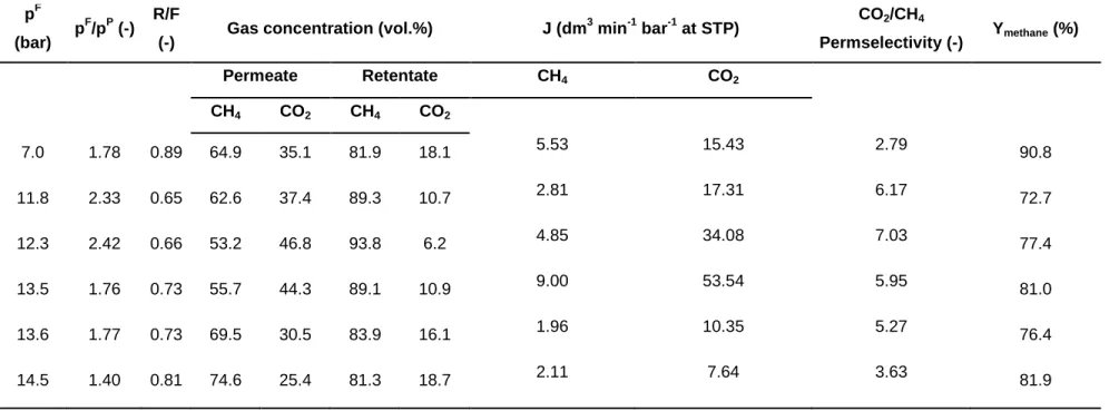
membrane bioreactor system – as documented by Szentgyörgyi et al. (2010) –
142
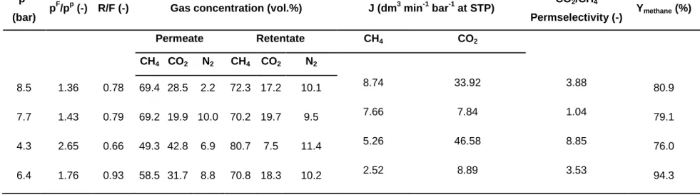
was collected over a period of time, compressed into a gas cylinder and
143
subsequently tested. Recently, together with our industrial partner, work has
144
commenced on the valorization of landfill-deposited organic waste fractions, i.e.
145
to generate biogas. As a part of that line of research, the assessment of methane
146
purification by membrane technologies is a distinct goal. In accordance with a
147
summary in the paper of Brunetti et al. (2015), the nitrogen content in biogas can
148
vary considerably (1-17 vol.%). Hence, to simulate realistic conditions and typical
149
compositions of landfill-derived biogas, enrichment of the real gaseous mixture
150
(pressurized in the external tank, as noted above) by N2 was conducted. As a
151
result, the final composition was as follows: 70 vol.% CH4, 19.8 vol.% CO2, 9.2
152
vol.% N2 and approx. 1 vol.% unidentified minor impurities.
153
As can be observed in Tables 1 and 2, the effect of the main membrane
154
operating parameters – namely the (i) feed pressure to permate pressure ratio
155
7
(pF/pP) and (ii) the splitting factor (R/F) defined as the retentate flow rate relative
156
to the total feed flow rate – on (i) methane concentration on the side of the
157
retentate and (ii) methane recovery was sought (Figs. 2-5). All data presented in
158
this work were obtained under steady-state permeation conditions, reflected by
159
the properly stabilized volumetric flows and corresponding concentrations of
160
gaseous substances, namely CH4, CO2 and N2. In addition to the experimental
161
runs listed in Tables 1 and 2, the membrane module was tested at a biogas
162
plant located in Hungary in order to determine its behaviour in the longer-term
163
and provide feedback concerning the stability of this time-dependent process,
164
which could be useful as far as an envisaged industrial application is concerned.
165
The respective permeation conditions are described in Table 3. Mass balance
166
calculations, that took into account volumetric flow rates and respective
167
concentrations of gases, thoroughly verified the reliability of such measurements.
168
This indicated that the entire feed could only be extracted either as the retentate
169
or permeate after separation had occurred. Repetitions (i.e. duplicates) under
170
particular experimental settings were carried out occasionally, resulting in relative
171
deviations < 5 %.
172 173
3. Analytical methods
174 175
Gas samples taken from the feed, permeate and retentate were analyzed
176
by gas chromatography. On the one hand, the concentrations of CH4 and N2
177
could be determined from a Gow-Mac Series 600 gas chromatograph equipped
178
with a molecular sieve packed column (filled with zeolite), a thermal conductivity
179
detector (TCD), and He as a carrier gas. On the other hand, the concentration of
180
CO2 was analyzed by a Hewlett Packard HP 5890 Series II gas chromatograph
181
equipped with a capillary column (GS-CarbonPLOT, Agilent Technologies), a
182
TCD and N2 as a carrier gas.
183
8 4. Calculations
184 185
CH4 recovery (Ymethane) was defined (in the unit of %) according to Eq. 1:
186 187
Ymethane = 100
188 (1)
189
where and are the total volumetric flow rates of the retentate and feed
190
(dm3 min-1 at standard temperature (273 K) and pressure (1 bar) (STP)),
191
respectively; while and stand for the CH4 concentrations (vol.%)
192
in these fractions, respectively (Tables 1-3).
193
The experimental, pressure-normalized volumetric gas flow rate ( ) of a
194
given component (j) in the mixture for the PI membrane module was computed
195
(in the unit of dm3 min-1 bar-1 at STP), as follows (Eq. 2):
196 197
= (2)
198
199
where isthe total volumetric flow rate of the permeate (dm3 min-1 at STP), is
200
the actual (measured) concentration of component (j) in the permeate (vol.%),
201
and (in the unit of bar) is the mean pressure gradient across the
202
membrane capillaries (Asadi et al., 2016) or, in other words, the partial driving
203
force of component (j), according to Eq. 3.
204 205
=
–
(3)
206
9
where and are the average partial pressures for component (j)
207
on the lumen-side (where the gas was fed) and the shell-side (where the
208
permeate was collected), respectively according to Asadi et al. (2016), assuming
209
in the calculation that the membrane permeate stream was under non-well-mixed
210
conditions.
211 212
The permselectivity (α) for a certain gas pair was defined by Eq. 4.
213 214
α =
(4)
215
216
where and are the experimental, pressure-normalized volumetric gas flow
217
rates of the rapidly and the slowly permeating compounds, (i) and (j), respectively
218
( > ). In this work, the permselectivities for CO2 and CH4, as major
219
constituents of biogas that need to be separated, were computed (Tables 1-3).
220 221
5. Methane enrichment and recovery from binary (model) and real
222
biogas mixtures
223 224
In essence, the gas separation applying non-porous, polymeric materials
225
e.g. in the case of UBE-CO5 requires the partial pressure difference of
226
substances across the membrane (Mulder, 1996), where the rapidly permeating
227
compound is enriched in the permeate, meanwhile, the slower (less-permeable)
228
one is concentrated in the retentate. Accordingly, on the grounds of carbon
229
dioxide enrichment on the permeate-side (Tables 1 and 2), it can be concluded
230
that the membrane used in this investigation is CO2-selective. This is primarily
231
10
attributed to the properties of PI, which act as the selective layer of composite
232
hollow fibers membranes found in the module. This glassy polymer can provide a
233
sufficient degree of CO2/CH4 selectivity given its high permeability of CO2, which
234
can be even an order of magnitude larger than that of CH4 (Harasimowicz et al.,
235
2007). The fact that the PI membrane is CH4-rejective (Tables 1 and 2) leads to
236
increased methane content in the retentate under upstream-side pressure
237
conditions. This is quite advantageous, especially when the (i) upgraded biogas,
238
namely biomethane, is to be injected into the distribution pipeline network
239
(Brunetti et al., 2015) or (ii) when a sufficient level of biogas purification is not
240
achieved in a single-stage, requiring further steps by means of additional
241
processing to reach the defined gas (biomethane) quality.
242
With both the binary (model) as well as real biogas mixtures employed in
243
this work, the achievable concentration of methane in the retentate seemed to be
244
positively influenced by the greater difference between and , which made a
245
particular contribution to the actual driving force (Eq. 4). This is reflected in Figs.
246
2 and 4, where the relationship between / and the CH4 concentration on the
247
retentate-side as well as the CO2/CH4 permselectivity can be regarded as directly
248
proportional. In addition, the so-called splitting factor (R/F) had also been proven
249
as a variable that exhibits a substantial impact on the performance of gas
250
separation (Bakonyi et al., 2013b; Harasimowicz et al., 2007). Based on Figs. 3
251
and 5, regardless of the gas actually fed into the module, the lower R/F range
252
should be preferred to attain a more significant degree of enrichment of methane
253
in the retentate and maintain a larger permselectivity of CO2/CH4. This
254
observation agrees well with the features generally described concerning the
255
technique of gas separation by membranes (Baker, 2000). Overall, by comparing
256
Fig. 2 with Fig. 4 and Fig. 3 with Fig. 5, the results demonstrate that the
257
composition of the gas used, either in terms of the model or real biogas, did not
258
remarkably change the profile of response given by the membrane as a function
259
11
of various operating conditions, namely / and R/F. Consequently, the
260
conclusion can be drawn that the process ought to be conducted by ensuring a
261
larger driving force along with a smaller splitting factor to enhance the
262
percentage of methane in the retentate. From the viewpoint of peak methane
263
concentrations on the retentate side, it should be pointed out that the
264
performance of the module (under comparable test conditions: / = 2.42-2.65,
265
R/F = 0.66) was less attractive attributed to the higher degree of complexity,
266
lower initial CH4 content, etc. of real biogas (Tables 1 and 2).
267
As a matter of fact, in terms of the model gas, the highest enrichment of
268
methane (93.8 vol.%) was accomplished with a corresponding recovery (Ymethane,
269
Eq. 1) of 77.4 % (Table 1). In the case of real biogas, however, the best recorded
270
methane concentration was 80.7 vol.% linked to 76 % of Ymethane (Table 2).
271
Hence, these results indicate that a retentate of almost biomethane quality (93.8
272
vs. 95 vol.%) could be delivered in the case of the model gas mixture. Therefore,
273
it can be presumed that following slight modifications of the process parameters,
274
i.e. raising the driving force and/or lowering the splitting factor, the target value of
275
95 vol.% could be realistic. On the contrary, further study is required to achieve a
276
similar degree of success with real biogas. As can be inferred from Table 2, the
277
membrane was unable to efficiently deal with the substantial N2 content of the
278
feed (Table 2), making this compound of major concern. To understand why only
279
marginal N2/CH4 separation could be realised, it should be kept in mind that the
280
permselectivity is dependent on particular factors such as (i) diffusivity and (ii)
281
solubility of the permeating compounds in the polymer material (Freeman, 1999).
282
The variation in the former term contributes to the so-called mobility selectivity,
283
while that of the latter parameter influences the commonly named sorption
284
selectivity. Unfortunately, in many cases these two characteristics are opposed to
285
each other when working with mixtures comprised of nitrogen as well as
286
methane. Therefore, no effective separation of these two gases can be
287
12
accomplished (Lokhandwala et al., 2010). Consequently, the elimination of N2
288
from the biogas stream is an objective of further research where membranes
289
possessing better characteristics are developed. Moreover, provided that the
290
overall technology undergoes careful optimization by reconsidering the number
291
of purification stages and the possible application of cascades (Baker and
292
Lokhandwala, 2008; Lokhandwala et al., 2010), additional benefits that enhance
293
the process can be expected. For comparison of membrane performance with
294
other materials/modules, data summarized in review articles such as Basu et al.
295
(2010) and Scholz et al. (2013) can be referenced. Among commercialized
296
polymer materials, permselectivity values for CO2/CH4 span 1.4-42.8 and hence,
297
the respective values attained with the commercialized PI module in this work
298
(Tables 1-3) fit well into this range.
299 300
6. Evaluation of the stability of the biogas upgrading process over
301
longer-term measurements – implications of application in the field
302 303
Apart from the issues elaborated in Section 5, e.g. the N2 content of the
304
biogas, the time-stability of the process is also a crucial aspect that must be
305
considered. In other words, to acquire a reasonable comprehension of the
306
relevance of the membrane module in terms of an actual application in the field
307
that attempts to improve the quality of the biogas, an adequate degree of process
308
durability should be acquired. Therefore, performance of the PI membrane
309
module was further analyzed over the longer-term by running permeation
310
experiments with real biogas (generated by an anaerobic digestion plant located
311
in the countryside of Hungary). Furthermore, implementation of the whole test rig
312
in an industrial setting is accompanied with the advantage of a continuous gas
313
supply and the availability of sufficient feed volumes, which would otherwise limit
314
the exploitation of permeation capacities over a more extensive period of time.
315
13
As can be seen in Table 3, the biogas generated in the plant could be
316
characterised as a clearly distinguishable quality compared to the one applied
317
during laboratory tests (Table 2). This might be attributed to differences in the
318
attributes of biotic and abiotic processes, i.e. in terms of the (i) composition of
319
underlying microbial consortia, (ii) source and complexity of the feedstock to be
320
utilized, (iii) operational settings of the fermenters, etc. During the permeation
321
stability tests, separation conditions were constants (Table 3) for almost 9 hours
322
during the experiment (Figs. 6 and 7). It should be noted that besides the clearly
323
identifiable components, namely CH4, CO2 and N2, the raw biogas, on average,
324
contains a comparable amount of trace substances to the biogas evolved in the
325
laboratory-scale bioreactor (Table 2). However, the similarities regarding the
326
distribution (partial concentrations) of these components remain unknown and
327
such an analysis could be a subject of a future study to elaborate on such related
328
effects. Actually, based on the already published experiences in the existing
329
literature, pro-longed operation of the biogas-upgrading membrane permeation
330
system can require the pretreatment of raw fermenter off-gas to get rid of
331
particular secondary components (i.e. ammonia, hydrogen sulfide and water
332
vapor that may damage the membrane material over time) by drying,
333
condesnation and desulphurization before conveying the biogas to the
334
membrane purification technology (Miltner et al., 2010, 2009). Such an action
335
can help to extend membrane lifetime and preserve its performance (Stern et al.,
336
1998)
337
The time profiles of the qualities of the permeate and retentate are
338
depicted in Figs. 6 and 7, respectively. It should be inferred that only slight
339
changes in the compositions were recorded and, therefore, the purification
340
performance could be considered quite stable throughout the test period.
341
Similarly to the results of the other gas mixtures discussed above, a considerable
342
degree of CH4/CO2 separation was achieved. However, the removal of nitrogen
343
14
gas seemed to be challenging, in accordance with statements made in Section 5.
344
Under the circumstances mentioned in Table 3, a reasonable and steady level of
345
CH4 recovery (Ymethane > 82 %) was accomplished with a corresponding methane
346
concentration of 81-82 vol.% in the retentate. Overall, these research outcomes
347
imply that the gas permeation process was able to function properly over an
348
extended period of time without considerable variation in the separation
349
efficiency. Thus, it can be deduced that the PI membrane employed may be a
350
worthy candidate for further investigation and possible installation at biogas
351
plants. However, the experiments conducted point to the fact that this particular
352
module should be applied as one component of a multi-stage (sequential)
353
membrane system, enriching the CH4 content of the biogas to the desired level of
354
biomethane quality (Makaruk et al., 2010). Such a system is supposed to
355
manage the efficient separation of N2 from CH4 and attain large Ymethane values to
356
reduce losses in the permeate (increase product recovery) (Rautenbach and
357
Welsch, 1993) and consequently, minimise the environmental impacts
358
associated with the emission of methane. Many times, however, high methane
359
purities may be attained only with compromises in methane recovery, when
360
some methane is lost in the permeate (Sun et al., 2015). Under these conditions,
361
for instance, the permeate with methane content can be recycled and burnt in
362
gas engines at the biogas plant (Miltner et al., 2009).
363 364
7. Conclusions
365 366
In this paper, a polyimide gas separation membrane was investigated in
367
terms of biogas purification. The results showed that the feed-to-permeate-
368
pressure ratio as well as the splitting factor had a notable effect on the
369
performance of the process. In fact, under actual operating circumstances, the
370
15
module provided biogas with methane content (93.8 vol.% along with 77.4 %
371
recovery) via efficient removal of CO2 in the case of the binary, model mixture.
372
The CO2/CH4 permselectivity values were dependent on the experimental
373
conditions and accordingly, could be as high as 11-12 in some cases. However,
374
primarily due to the insufficient CH4/N2 separation capacity of the membrane, it
375
was not possible to upgrade the real biogas in the same manner and additional
376
research into the subject is encouraged. Nevertheless, tests revealed an
377
adequate level of endurance of the membrane permeation process over the
378
longer-term, leading to the conclusion that the process, based on the module that
379
contains PI hollow fibers, is worthy of further elaboration under industrial
380
conditions in the field. The appropriate design of the process, in particular the
381
deployment of a membrane cascade purification system, could overcome the
382
existing bottleneck observed with the single-stage application to deliver
383
biomethane from biogas.
384 385
Acknowledgement
386 387
The authors would like to express their gratitude for the financial support
388
provided by the Széchenyi 2020 Programme under the project EFOP-3.6.1-16-
389
2016-00015, and by the Excellence of Strategic R+D Workshops under the
390
project GINOP-2.3.2-15 (which encompasses the development of modular,
391
mobile water treatment systems and wastewater treatment technologies based at
392
the University of Pannonia to enhance growing dynamic exportation from
393
Hungary between 2016 and 2020). The János Bolyai Research Scholarship of
394
the Hungarian Academy of Sciences is duly acknowledged for the support. This
395
work was supported by the Korea Research Fellowship Program through the
396
National Research Foundation of Korea (NRF) funded by the Ministry of Science
397
16
and ICT (Grant No: 2016H1D3A1908953).This work was supported by the New
398
& Renewable Energy Core Technology Program of the Korea Institute of Energy
399
Technology Evaluation and Planning (KETEP) granted financial resource from
400
the Ministry of Trade, Industry & Energy, Republic of Korea (No.
401
20173010092470).
402 403
References
404 405
Albo, J., Wang, J., Tsuru, T., 2014. Gas transport properties of interfacially
406
polymerized polyamide composite membranes under different pre-treatments
407
and temperatures. J. Membr. Sci. 449, 109-118.
408
Albo, J., Irabien, A., Non-dispersive absorption of CO2 in parallel and cross-
409
flow membrane modules using EMISE. J. Chem. Technol. Biotechnol. 87,
410
1502-1507.
411
Albo, J., Luis, P., Irabien, A., 2010. Carbon dioxide capture from flue gases
412
using a cross-flow membrane contactor and the ionic liquid 1-ethyl-3-
413
methylimidazolium ethylsulfate. Ind. Eng. Chem. Res. 49, 11045-11051.
414
Asadi, S., Hamed Mosavian, M.T., Ahmadpour, A., 2016. Effect of the
415
membrane operating parameters on the separation of oxygen and hydrogen
416
disulphide. Indian J. Chem. Technol. 23, 77-80.
417
Baker, R.W. Membrane technology and applications. 2nd edition, Wiley, 2000,
418
New York.
419
Baker, R.W., Lokhandwala, K., 2008. Natural gas processing with
420
membranes: An overview. Ind. Eng. Chem. Res. 47, 2109-2121.
421
Baker, R.W., Low, B.T., 2014. Gas separation membrane materials: A
422
perspective. Macromolecules 47, 6999-7013.
423
17
Bakonyi, P., Nemestóthy, N., Bélafi-Bakó, K., 2013a. Biohydrogen purification
424
by membranes: An overview on the operational conditions affecting the
425
performance of non-porous, polymeric and ionic liquid based gas separation
426
membranes. Int. J. Hydrogen Energy 38, 9673-9687.
427
Bakonyi, P., Kumar, G., Nemestóthy, N., Lin, C.Y., Bélafi-Bakó, K., 2013b.
428
Biohydrogen purification using a commercial polyimide membrane module:
429
Studying the effects of some process variables. Int. J. Hydrogen Energy 38,
430
15092-15099.
431
Bakonyi, P., Buitrón, G., Valdez-Vazquez, I., Nemestóthy, N., Bélafi-Bakó, K.,
432
2017. A novel gas separation integrated membrane bioreactor to evaluate the
433
impact of self-generated biogas recycling on continuous hydrogen
434
fermentation. Appl. Energy 190, 813-823.
435
Basu, S., Khan, A.L., Cano-Odena, A., Liu, C., Vankelecom, I.F.J., 2010.
436
Membrane-based technologies for biogas separations. Chem. Soc. Rev. 39,
437
750-768.
438
Bauer, F., Persson, T., Hulteburg, C., Tamm, D., 2013. Biogas upgrading –
439
technology overview, comparison and perspectives for the future. Biofuels
440
Bioprod. Bioref. 7, 499–511.
441
Brunetti, A., Sun, Y., Caravella, A., Drioli, E., Barbieri, G., 2015. Process
442
Intensification for greenhouse gas separation from biogas: More efficient
443
process schemes based on membrane-integrated systems. Int. J. Greenh.
444
Gas Con. 35, 18-29.
445
Chen, X.Y., Vinh-Thang, H., Ramirez, A.A., Rodrigue, D., Kaliaquine, S.,
446
2015. Membrane gas separation technologies for biogas upgrading. RSC
447
Adv. 5, 24399-24448.
448
Ferella, F., Puca, A., Taglieri, G., Rossi, L., Gallucci, K., 2017. Separation of
449
carbon dioxide for biogas upgrading to biomethane. J. Clean. Prod. 164,
450
18 1205-1218.
451
Freeman, B.D., 1999. Basis of permeability/selectivity tradeoff relations in
452
polymeric gas separation membranes. Macromolecules 32, 375-380.
453
Ge, X., Xu, F., Li, Y., 2016. Solid-state anaerobic digestion of lignocellulosic
454
biomass: Recent progress and perspectives. Bioresour. Technol. 205, 239-
455
249.
456
Harasimowicz, M., Orluk, P., Zakrzewska-Trznadel, G., Chmielewski, A.G.,
457
2007. Application of polyimide membranes for biogas purification and
458
enrichment. J. Hazard. Mater. 144, 698-702.
459
Lokhandwala, K.A., Pinnau, I., He, Z., Amo, K.D., DaCosta, A.R., Wijmans,
460
J.G., Baker, R.W., 2010. Membrane separation of nitrogen from natural gas: A
461
case study from membrane synthesis to commercial deployment. J. Membr.
462
Sci. 34, 270–279.
463
Makaruk, A., Miltner, M., Harasek, M., 2010. Membrane biogas upgrading
464
processes for the production of natural gas substitute. Sep. Purif. Technol. 74,
465
83-92.
466
Miltner, M., Makaruk, A., Harasek, M., 2017. Review on available biogas
467
upgrading technologies and innovations towards advanced solutions. J.
468
Clean. Prod. 161, 1329-1337.
469
Miltner, M., Makaruk, A., Harasek, M., 2010. Investigation of the long-term
470
performance of an industrial-scale biogas upgrading plant with grid supply
471
applying gas permeation membranes. Chem. Eng. Trans. 21, 1213-1218.
472
Miltner, M., Makaruk, A., Bala, H., Harasek, M., 2009. Biogas upgrading for
473
transportation purposes – operational experiences with Austria’s first Bio-CNG
474
fuelling station. Chem. Eng. Trans. 18, 617-622.
475
Morero, B., Groppelli, E.S., Campanella, E.A., 2017. Evaluation of biogas
476
19
upgrading technologies using a response surface methodology for process
477
simulation. J. Clean. Prod. 141, 978-988.
478
Mulder, M.H.V. Basic Principles of Membrane Technology. Kluwer Academic
479
Publishers, 1996, Dordrecht.
480
Niesner, J., Jecha, D., Stehlík, P., 2013. Biogas Upgrading Technologies:
481
State of Art Review in European Region. Chem. Eng. Trans. 35, 517-522.
482
Patinvoh, R.J., Osadolor, O.A., Chandolias, K., Sárvári Horváth, I.,
483
Taherzadeh, M.J., 2017. Innovative pretreatment strategies for biogas
484
production. Bioresour. Technol. 224, 13-24.
485
Pavi, S., Kramer, L.E., Gomes, L.P., Miranda, L.A.S., 2017. Biogas production
486
from co-digestion of organic fraction of municipal solid waste and fruit and
487
vegetable waste. Bioresour. Technol. 228, 362-367.
488
Rasi, S., Lantela, J., Rintala, J., 2011. Trace compounds affecting biogas
489
energy utilisation – A review. Energy Conv. Manage. 52, 3369-3375.
490
Rasi, S., Veijanen, A., Rintala, J., 2007. Trace compounds of biogas from
491
different biogas production plants. Energy 32, 1375-1380.
492
Rautenbach, R., Welsch, K., 1993. Treatment of landfill gas by gas
493
permeation—pilot plant results and comparison to alternatives. Desalination
494
90, 193-207.
495
Ryckebosch, E., Drouillon, M., Vervaeren, H., 2011. Techniques for
496
transformation of biogas to biomethane. Biomass Bioenergy 35, 1633-1645.
497
Scholz, M., Melin, T., Wessling, M., 2013. Transforming biogas into
498
biomethane using membrane technology. Renew. Sustain. Energy Rev. 17,
499
199-212.
500
Szentgyörgyi, E., Nemestóthy, N., Bélafi-Bakó, K., 2010. Anaerobic moving
501
bed biofilm fermenter for biogas production. Environ. Prot. Eng. 36, 117-125.
502
20
Stern, S.A., Krishnakumar, B., Charati, S.G., Amato, W.S., Friedman, A.A.,
503
Fuess, D.J., 1998. Performance of a bench-scale membrane pilot plant for the
504
upgrading of biogas in a wastewater treatment plant. J.Membr. Sci. 151, 63-
505 506 74.
Sun, Q., Li, H., Yan, J., Liu, L., Yu, Z., Yu, X., 2015. Selection of appropriate
507
biogas upgrading technology – a review of biogas cleaning, upgrading and
508
utilisation. Renew. Sustain. Energy Rev. 51, 521-532.
509
Weiland, P., 2010. Biogas production: current state and perspectives. Appl.
510
Microbiol. Biotechnol. 85, 849-860.
511 512
21
Figure legends
513 514
Fig. 1 – Image of the gas separation membrane system (left-hand side) with
515
the PI membrane module installed (right-hand side).
516
Fig. 2 – The effect of pF/pp on the methane concentration on the retentate
517
side (diamond) and CO2/CH4 permselectivity (square) using the model
518
biogas.
519
Fig. 3 – The effect of the splitting factor (R/F) on the methane concentration
520
on the retentate side (diamond) and CO2/CH4 permselectivity (square) using
521
the model biogas.
522
Fig. 4 – The effect of pF/pp on the methane concentration on the retentate
523
side (diamond) and CO2/CH4 permselectivity (square) using the real biogas.
524
Fig. 5 – The effect of the splitting factor (R/F) on the methane concentration
525
of the retentate side (diamond) and CO2/CH4 permselectivity (square) using
526
the real biogas.
527
Fig. 6 – The time dependency of the composition of the permeate under the
528
conditions listed in Table 3. Square: carbon dioxide; Diamond: methane;
529
Triangle: nitrogen.
530
Fig. 7 – The time dependency of the composition of the retentate under the
531
conditions listed in Table 3. Square: carbon dioxide; Diamond: methane;
532
Triangle: nitrogen.
533 534
22
Table 1 – Experimental conditions and results using the binary gas mixture (80 vol.% CH4, 20 vol.% CO2)
pF
(bar) pF/pP (-) R/F
(-) Gas concentration (vol.%) J (dm3 min-1 bar-1 at STP) CO2/CH4
Permselectivity (-) Ymethane (%)
Permeate Retentate CH4 CO2
CH4 CO2 CH4 CO2
7.0 1.78 0.89 64.9 35.1 81.9 18.1 5.53 15.43 2.79 90.8
11.8 2.33 0.65 62.6 37.4 89.3 10.7 2.81 17.31 6.17 72.7
12.3 2.42 0.66 53.2 46.8 93.8 6.2 4.85 34.08 7.03 77.4
13.5 1.76 0.73 55.7 44.3 89.1 10.9 9.00 53.54 5.95 81.0
13.6 1.77 0.73 69.5 30.5 83.9 16.1 1.96 10.35 5.27 76.4
14.5 1.40 0.81 74.6 25.4 81.3 18.7 2.11 7.64 3.63 81.9
23
Table 2 – Experimental conditions and results using the biogas mixture containing 70 vol.% CH4, 19.8 vol.% CO2, 9.2 vol.% N2 and unknown trace substances to balance.
pF
(bar) pF/pp (-) R/F (-) Gas concentration (vol.%) J (dm3 min-1 bar-1 at STP) CO2/CH4
Permselectivity (-) Ymethane (%)
Permeate Retentate CH4 CO2
CH4 CO2 N2 CH4 CO2 N2
8.5 1.36 0.78 69.4 28.5 2.2 72.3 17.2 10.1 8.74 33.92 3.88 80.9
7.7 1.43 0.79 69.2 19.9 10.0 70.2 19.7 9.5 7.66 7.84 1.04 79.1
4.3 2.65 0.66 49.3 42.8 6.9 80.7 7.5 11.4 5.26 46.58 8.85 76.0
6.4 1.76 0.93 58.5 31.7 8.8 70.8 18.3 10.2 2.52 8.89 3.53 94.3
24
Table 3 – Average experimental conditions for the assessment of process stability during longer-term biogas (57.4 vol.%
CH4, 39 vol.% CO2, 2.5 vol.% N2 and unknown trace substances to balance) permeation conducted at 50 oC.
pF (bar) pF/pp (-) R/F (-) Gas concentration (vol.%) J (dm3 min-1 bar-1 at STP) CO2/CH4
Permselectivity (-) Ymethane (%)
Permeate Retentate CH4 CO2
CH4 CO2 N2 CH4 CO2 N2
10.8 5.48 0.58 21.6 75.8 1.4 81.7 14.6 2.9 1.07 12.55 11.77 82.9
25 Fig. 1
26 Fig. 2
80 82 84 86 88 90 92 94 96
0 1 2 3 4 5 6 7 8
1.2 1.4 1.6 1.8 2 2.2 2.4 2.6
Methane concentration in retentate (vol.%) CO2/CH4 selectivity (-)
pF/pP (-)
27 Fig. 3
78 80 82 84 86 88 90 92 94 96
0 1 2 3 4 5 6 7 8
0.6 0.65 0.7 0.75 0.8 0.85 0.9 0.95
Methane concentration in retentate (vol.%) CO2/CH4 selectivity (-)
R/F (-)
28 Fig. 4
68 70 72 74 76 78 80 82
0 1 2 3 4 5 6 7 8 9 10
1 1.5 2 2.5 3
Methane concentration in retentate (vol.%) CO2/CH4 selectivity (-)
pF/pP (-)
29 Fig. 5
66 68 70 72 74 76 78 80 82
0 1 2 3 4 5 6 7 8 9 10
0.6 0.65 0.7 0.75 0.8 0.85 0.9 0.95
Methane concentration in retentate (vol.%) CO2/CH4 selectivity (-)
R/F (-)
30 Fig. 6
0 10 20 30 40 50 60 70 80 90
0 1 2 3 4 5 6 7 8 9
Gas concentration in permeate (vol.%)
Time (h)
31 Fig. 7
0 10 20 30 40 50 60 70 80 90
0 1 2 3 4 5 6 7 8 9
Gas concentration in retentate (vol.%)
Time (h)
1 2 3 4 5 6 7 8 9 10 11 12 13 14 15 16 17 18 19 20 21 22 23 24 25 26 27 28 29 30 31 32 33 34 35 36 37 38 39 40 41 42 43 44 45 46 47 48 49 50 51 52 53 54 55 56 57 58 59 60 61 62 63 64 65
1
(Word count: 5488) 1
Evaluation of a membrane permeation system for biogas upgrading using model 2
and real gaseous mixtures: The effect of operating conditions on separation 3
behaviour, methane recovery and process stability 4
5
Nándor Nemestóthy1, Péter Bakonyi1,*, Eszter Szentgyörgyi1, Gopalakrishnan
6
Kumar2, Dinh Duc Nguyen3, Soon Woong Chang3, Sang-Hyoun Kim2, Katalin
7
Bélafi-Bakó1
8
9
1Research Institute of Bioengineering, Membrane Technology and Energetics,
10
University of Pannonia, Egyetem u. 10, 8200 Veszprém, Hungary
11
2School of Civil and Environmental Engineering, Yonsei University, Seoul 38722,
12
Republic of Korea
13
3Department of Environmental Energy Engineering, Kyonggi University, Suwon
14
16227, Republic of Korea
15
16
*Corresponding Author: Péter Bakonyi
17
Tel: +36 88 624385
18
Fax: +36 88 624292
19
E-mail: bakonyip@almos.uni-pannon.hu
20 21
*Revised Manuscript - Clean Version Click here to view linked References