IP: 193.22.15.105 On: Sat, 08 Dec 2018 13:11:52 Copyright: American Scientific Publishers
Delivered by Ingenta
Copyright © 2019 American Scientific Publishers All rights reserved
Printed in the United States of America
Article
Journal of Nanoscience and Nanotechnology Vol. 19, 422–428, 2019 www.aspbs.com/jnn
Synthesis, Characterization and Photocatalytic Efficiency of ZnO/MWCNT Nanocomposites Prepared Under
Different Solvent Conditions
E. Bartfai
1, K. Nemeth
1, B. El Mrabate
2, M. Udayakumar
2, K. Hernadi
1, and Z. Nemeth
12∗1Department of Applied and Environmental Chemistry, University of Szeged, Rerrich Béla tér 1, Szeged, H-6720, Hungary
2Institute of Chemistry, University of Miskolc, Miskolc-Egyetemváros, Miskolc, H-3515, Hungary
Here we report the application of zinc oxide (ZnO) coated multi-walled carbon nanotube (MWCNT) composites in the photocatalytic decomposition of acetaldehyde (AA). Zinc oxide nanoparticles were successfully coated on the multi-walled carbon nanotube via impregnation process using zinc acetate (Zn(CH3COO)2×2H2O) as precursor and sodium dodecyl sulfate (SDS) treated multi- walled carbon nanotube as raw material under different solvent conditions. The applied solvents during preparation were ethanol (EtOH) and water (H2O). As-prepared materials were character- ized by thermal analysis (TG), X-ray diffraction (XRD), specific surface area measurement (BET) and transmission electron microscopy (TEM) techniques. Photocatalytic efficiencies of as-prepared composites were investigated in a stationary reactor equipped with UV lamp. Decomposition of acetaldehyde was followed by using gas chromatography (GC). Observations revealed that using impregnation method and different solvents the preparation of ZnO/MWCNT nanocomposites can be controlled easily. The highest degradation rate was achieved with the nanocomposite was syn- thetized using ethanol as solvent. The photocatalytic experiments revealed that the composite has higher photocatalytic activity than that of both the zinc oxide nanoparticles and the mechanical mixture of multi-walled carbon nanotube and zinc oxide.
Keywords: Nanocomposite, Zinc Oxide, Transmission Electron Microscopy, Photocatalysis, Gas Chromatography.
1. INTRODUCTION
Nowadays, scientists are inspired to find alternative pro- cedures for solving the problems with the water contami- nants and pollutants predicted. One of these trends is the development of photoactive carbon based nanocomposites, in which numerous promising semiconductors have been tested.1
Carbon nanotubes (CNTs) have exceptional properties thereby resulting in many potential applications.2, 3 Due to their high specific surface area and adsorption capabil- ity multi-walled carbon nanotube (MWCNT) have been increasingly used in environmental applications.4As a sup- port for semiconductor with photocatalytic properties car- bon nanotubes has certain advantages because it is inert in the most reaction conditions, they can provide high dispersion of semiconductor photocatalysts and creates many active sites for the photocatalytic decomposition.5
∗Author to whom correspondence should be addressed.
As it reported earlier MWCNT can conduct electrons and also could have high adsorption capacity for certain organic substrates.6
The major drawback in photocatalysis is to have a chance of recombination of charges avoiding photodegra- dation. This electron–hole recombination can be prevented by making a composite MWCNT material with other semi- conductor nanoparticles or metal oxides. MWCNT cap- tured electrons due to its high charge conducting ability that ultimately gives less chance to electrons for recombining with holes. So, MWCNT can be called as photo-generated electron acceptor that enhances interfacial electron trans- fer process, whereas the semiconductors are good electron donors under irradiation.7–10Applying different preparation methods, many types of semiconductor metal oxides, such as TiO2,11, 12 SnO2,13 Cu2O,14 CeO215 and ZnO16–18 have been coated on MWCNT in earlier studies.
As a promising semiconductor material with a wide band gap of 3.37 eV and a large exciton binding energy
IP: 193.22.15.105 On: Sat, 08 Dec 2018 13:11:52 Copyright: American Scientific Publishers
Delivered by Ingenta face of MWCNT with ZnO nanoparticles.24–26 Koh et al.
also reported the coating of ZnO nanorods on MWCNT using hydrothermal synthesis.27CNTs decorated with ZnO nanoparticles were synthesized by Chen et al. through oxidization, amination and modification of MWCNT with H2SO4, NH3 and HNO3.28 Li et al. synthesized ZnO-MWCNT-reduced graphene oxide (RGO) ternary nanocomposites via a simple one-pot hydrothermal pro- cess using graphene oxide (GO)-dispersed MWCNT and zinc nitrate as raw materials.29
Since CNTs are chemically inert surface modification of carbon nanotubes are required to promote the attach- ment of nanoparticles. Covalent modification of the nano- tube sidewalls could change the electronic properties of the nanotubes. Noncovalent modification of MWCNT could be a promising alternative to prepare MWCNT based nanocomposites.30In order to favor the dispersion of CNTs in water the widely and most used approach is the adsorp- tion of surfactants onto the nanotube sidewalls. Their main advantages are their cheapness, their ready commercial disposability and simplicity of use. These small molecules have typically a hydrophobic tail and a hydrophilic head group, the former is intended to favor adsorption onto the hydrophobic nanotube walls and the latter to pro- mote affinity with the aqueous bulk solvent.31 As Jiang et al. reported sodium dodecyl sulfate (SDS) can noncova- lently modify the MWCNT surface through hydrophobic interaction.32
In hybrid systems, control of the particle size and mor- phology by a facile and low cost method is essential to their applications in photocatalytic reactions. The aim of this work was to present a simple route to produce ZnO nanoparticles on the surface of modified MWCNT.
Procedures were developed to form coatings on the surface of MWCNT under solvent conditions applying impregnation method. The acetaldehyde (AA) decomposi- tion reactions were used to test the photocatalytic efficien- cies of ZnO-covered MWCNT nanocomposites.
2. EXPERIMENTAL DETAILS 2.1. Materials
As it was described in our earlier papers [33, 34]
MWCNT was prepared by the catalytic chemical vapour
G and G peaks. The purity of the carbon phase can be easily determined by the rations of these three peaks, and the metal content was previously regarded with a quanti- tative ICP-MS analysis.37This analysis and peak intensity ratios in case of MWCNT indicate good quality and highly graphitic nature.
For composite fabrication all chemical reagents, such as zinc acetate (Zn(CH3COO)2×2H2O) and sodium- dodecyl-sulphate (SDS) purchased from Sigma-Aldrich, were analytical grade and used without further purification.
Distilled water and absolute ethanol (EtOH-VWR Prolabo) were used as the solvents of the precursor compound.
2.2. Modification of MWCNT and Nanocomposite Preparation
The chemical adsorption of SDS molecules on the surface of the MWCNT induces electrostatic repulsion between polar heads that expose in the aqueous solution thus pre- venting CNTs aggregation and inducing the formation of stable black suspensions. Noncovalent functionaliza- tion of MWCNT is necessary, therefore pristine nano- tubes were dispersed in 2 wt% dilute SDS aqueous solution31 to modify MWCNT surface by ultrasonication.
The ZnO/MWCNT composites were prepared by a sim- ple impregnation method. Surface treated MWCNT was applied as raw material and Zn(CH3COO)2×2H2O as pre- cursor compound. MWCNT contents were fixed at 10 wt%
of the total ZnO/MWCNT composites calculated to the final crystallized product after annealing. Initially, 0.1 g SDS modified MWCNT was dispersed in 50 mL water and EtOH via ultrasonication for 15 min. During this time the calculated amount of precursors (2.45 g) was dissolved in another 50 mL of water and EtOH. To completely dis- solve the precursors, the solution was stirred vigorously using a magnetic stirrer for 10 min at 300 rpm. Finally, the solution of the precursor was added drop by drop (∼2 mL/min) to the MWCNT suspension under contin- uous stirring. Then, the mixture was heated to 40 C to evaporate EtOH and 70C to evaporate H2O on a hot plate.
Composite powder was further dried at 70 C in air for 12 h. Finally, the as-prepared nanomaterials were annealed in a static furnace in air with a heating rate of 5 C/min for 3 h at 300C to obtain crystalline ZnO. The reference
IP: 193.22.15.105 On: Sat, 08 Dec 2018 13:11:52 Copyright: American Scientific Publishers
Delivered by Ingenta
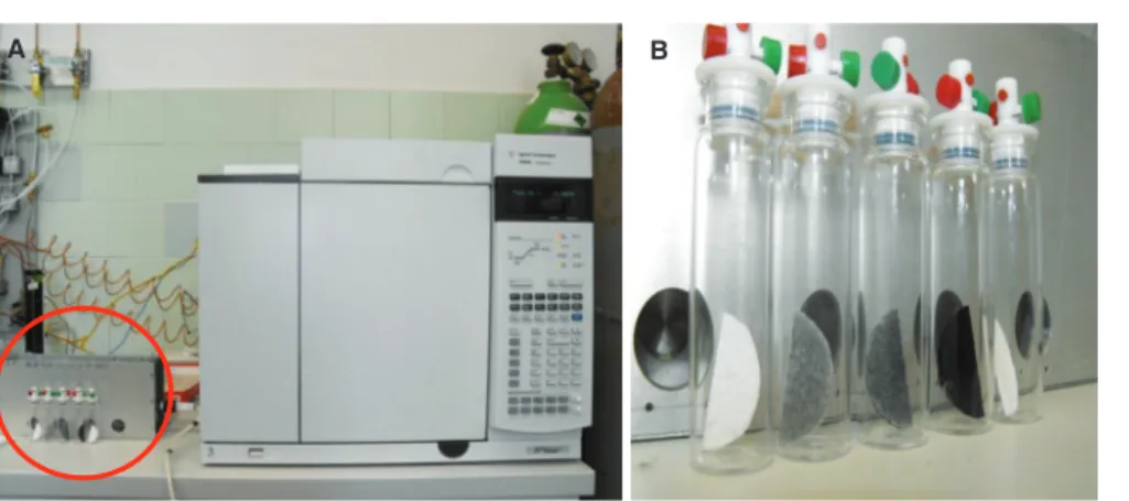
A B
Figure 1. UV photoreactor (left corner—A) with GC (A) and glass vials with ZnO/MWCNT nanocomposites, pristine ZnO, alumina paper and MWCNT (B).
materials of ZnO for comparative examinations were pre- pared exactly in the same way as the composites without the presence of MWCNT.
2.3. Sample Characterization
The formation of inorganic nanoparticles on the sur- face of MWCNT was verified by transmission electron microscopy (TEM, Philips CM10). For TEM investiga- tions, a small amount of the sample was sonicated in 1.25 mL of distilled water. Then, a few drops of this sus- pension were dribbled onto the surface of the grid (LC200- Cu TEM grid covered with lacey carbon film-Electron Microscopy Sciences-USA). The crystalline structure of the as-prepared membrane was determined by powder X-ray diffraction method (Rigaku Miniflex II Diffractome- ter) utilizing characteristic X-ray (CuK(=15405 Å)) radiation. Scanning was carried out over a 2 range of 10–80 with a step size of 0.0167. The specific surface areas of the samples were determined by the adsorption of nitrogen at 77 K according to the method of Brunauer- Emett-Teller.38 After the samples were pre-treated at 300 C for 15 min in helium atmosphere (50 mL/min), measurements were carried out by a single point BET instrument (BEL Japan Inc. BELCAT-A). Thermogravi- metric analysis (NETZSCH STA 409 PC connected to a Pfeiffer QMS 200 mass spectrometer system) was per- formed in air (measurement range: 25–800C, flow veloc- ity: 40 mL/min, heating rate 10 C/min) using 100 mg sample.
2.4. Determination of Photocatalytic Efficiency Photocatalytic experiments were carried out using the sys- tem which can be seen in Figure 1. The applied UV pho- toreactor (Fig. 1(A)—marked by red circle) was equipped with fluorescent lamp (Vilber-Lourmat T-6L UV-A, 6 W power, radiation maximum at 365 nm). The added amounts of the photocatalysts were 0.5 g/L, and AA, a harmful chemical material, (Spektrum3D, 99.0%) was used to char- acterize the photocatalytic activity of the specimen.
First, MWCNT composites were suspended in EtOH with a concentration of 0.5 mg/mL. In the next step 100 mL portions of these ZnO/MWCNT suspensions were deposited onto a high purity alumina based ceramic papers (COTRONICS Corporation-Ultra Temp 300)39with a diameter of 47 mm by simple filtration, enhanced with vacuum suction. Every suspension was used within a few hours to avoid MWCNT aggregation, which could alter the final performance of the membranes. As a final step, the as-prepared MWCNT composite membranes were dried on 100 C for 30 minutes in order to remove residual solvents. As-prepared alumina based ceramic membranes, with a load of 0.75 mg/cm2(50 mg/membrane), were cut into half to fit into the sample vial easily and placed into glass vials equipped with opening and locker plastic head as can be seen in Figure 1(B). Glass vials were rinsed with N2gas before starting the photocatalytic decomposi- tion of AA. Then, vials were filled with saturated vapour of AA (0,987 bar; 20 C; 0.9 mM) and wait until the adsorption equilibrium state (∼40 min). Vials were placed into a stationary reactor and irradiated the specimen in AA atmosphere with a wavelength of 365 nm at room tem- perature for 120 min. Changes in AA concentrations were followed with gas chromatograph (Agilent 6890 N) using a HP-PLOT Q column, equipped with thermal conductiv- ity (TC) and flame ionization (FI) detectors and Agilent 5975C VL MSD mass-spectrometer. The split ratio was 10:1 in all cases. Each nanocomposite sample was tested three times. As it was reported previously several types of intermediates can be generated during the decomposi- tion of AA (e.g., formaldehyde, acetic acid),40 however, the main product was CO2. In this report the determination of CO2 by gas chromatography was performed.
3. RESULTS AND DISCUSSION
3.1. Heat Treatment, Crystal Structure Analysis and Surface Area Measurement
In order to identify the ZnO nanoparticles and also to transform the amorphous phase into crystalline phase,
IP: 193.22.15.105 On: Sat, 08 Dec 2018 13:11:52 Copyright: American Scientific Publishers
Delivered by Ingenta
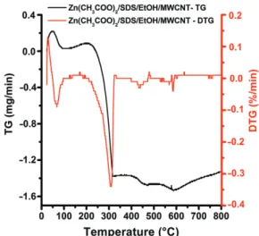
Figure 2. Thermal analysis of Zn(CH3COO)2 × 2H2O/SDS/
EtOH/MWCNT nanocomposite material.
the composite samples were heat treated. Before that the DTG gave us important information about the phase trans- formations which occurred because of the rise of the tem- perature (Fig. 2). The first thermal event was observed up to 100 C with a ∼14.9% weight loss. This weight loss can be attributed to the thermal dehydration of zinc acetate dihydrate and more specifically to the loss of the two water molecules. By further increasing the tempera- ture, the decomposition of anhydrous Zn(CH3COO)2 into ZnO occurs at ∼250 C, and is completed at ∼300 C with a∼28.8% weight loss. Beyond this temperature, and up to 400 C, the formation of stable ZnO crystal takes place. Based on these results, we decided to carry out the calcination at 300C for 3 h, since a stable ZnO phase is obtained. These observations are also in good agreement with previously reported result.41 Further thermal event can be noticed from 450 C to 550 C with a ∼4.8%
weight loss, which belongs to the burning of SDS modified MWCNT.
The degree of crystallization of composite samples was investigated by XRD. The results of analysis are presented in Figure 3. The diffraction peak at 2 =265 can be identified as the 002 reflection of MWCNT. The other diffraction peaks in the range of 20<2 <80 corre- spond to the (100), (002), (101), (102), (110), (103), (200), (112), (201), (004) reflections of ZnO. The average crys- talline size of inorganic particles can also be estimated from X-ray diffractograms by the Scherrer equation:42
D=K/ cos
WhereDis the diameter (in nanometer) of the grain or the layer, K is the shape factor (0.89), is the X-ray wave- length of Cu K (0.154 nm), is the experimental full- width half maximum of the respective diffraction peak(s), and is the Bragg angle. Furthermore, from the analysis of the TEM pictures, the average particle sizes were also
Figure 3. X-ray diffractograms of heat treated raw materials and ZnO/MWCNT nanocomposite sample prepared in EtOH.
calculated using iTEM software (Olympus Soft Imaging Solutions). The particle size distribution was determined by measuring the size of 100 particles in case of all sam- ples. We took into consideration that the TEM images only show a 2D projection of the 3D particles, thus the observed particle size distribution is actually a distribu- tion of the projected dimension of the particles. Particle size values obtained with the two different calculations showed good agreement. Table I shows the average par- ticle diameters (davin nanometers, calculated from TEM and XRD investigations. In case of pure MWCNT, TEM images were used only to determine the average diame- ter. As-prepared MWCNT-based filter materials were also characterized by N2adsorption technique to measure their specific surface area. Table I shows the measured specific surface area values.
3.2. TEM Analysis
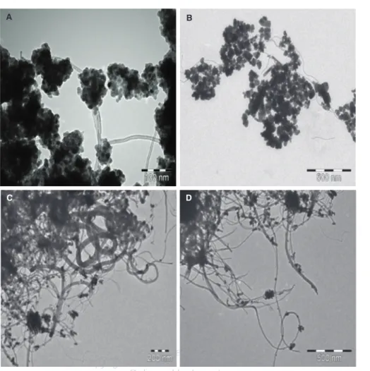
After the heat treatment MWCNT based composite sam- ples were investigated by TEM technique. Figure 4 shows TEM micrographs at various magnifications of the pre- pared ZnO/MWCNT nanocomposites. The fabrication of ZnO/MWCNT composites using Zn(CH3COO)2×2H2O as precursor and SDS modified MWCNT was success- ful using both of solvents, although different compos- ite structures were observed during TEM observations.
Figures 4(A)–(B) shows representative electron micro- graphs obtained from the investigation of composite mate- rials prepared in ethanol. TEM images revealed that the majority of MWCNT were covered by ZnO nanoparticles
Table I. Particle size and specific surface area of raw materials and MWCNT based composites.
Sample name daverage(nm) BET (m2/g)
MWCNT 35.8 (TEM) 1821
ZnO 15.1 (TEM and XRD) 512
ZnO/MWCNT/EtOH 20.2 (TEM and XRD) 643
ZnO/MWCNT/H2O 23.4 (TEM and XRD) 618
IP: 193.22.15.105 On: Sat, 08 Dec 2018 13:11:52 Copyright: American Scientific Publishers
Delivered by Ingenta
A
C D
B
Figure 4. TEM images of ZnO/MWCNT nanocomposites applying EtOH (A, B) and water (C, D) as solvent.
and segregated particles could not be observed during anal- ysis. Figures 4(C)–(D) present views of the nanocomposite sample prepared in water and these images clearly demon- strated that the surface of MWCNT was covered weakly with ZnO nanoparticles. Larger, segregated ZnO crystal- lites and uncovered MWCNT were also observed when water was used as solvent. Analysing as-prepared prod- ucts it can be concluded that EtOH provide more uniform ZnO/MWCNT nanocomposite samples. In previously pub- lished results, ZnO crystallites with different morphologies can be observed by using different solvents, such as water, ethanol and n-propanol.43 The surface tensions of these solvents are very different from each other, so the final composite morphology can be varied easily by changing the solvent.
3.3. Photocatalytic Efficiency
Before photocatalytic measurements, blank experiments were carried out to determine the decomposition of AA without any photocatalysts. The AA transformation was below 5% during 120 min long irradiation. The adsorption capacities of laboratory-prepared nanocomposites were also measured in dark experiences. Results pointed out that nanocomposites produced via the utilization of EtOH
solvent during the synthesis method resulted in higher adsorption ability. These materials adsorbed 10–15% of AA at applied concentration after 120 min. in dark, while nanocomposites produced in water solution adsorbed only 5–8% of AA. The estimated difference in adsorption capacities can not be connected to the specific surface areas, since these properties of the materials are very sim- ilar (see Table I). The difference probably due to some unclarified special surface property, resulted by the differ- ent solvents applied during synthesis methods. The adsorp- tion capacity of pristine alumina ceramic paper was also investigated under dark conditions. Pure alumina mem- brane adsorbed only 1–3% of AA (Fig. 5—brown curve).
The photocatalytic behaviors of the raw materials, the pure alumina ceramic paper, the simple mechanical mix- ture of MWCNT and ZnO, and ZnO/MWCNT compos- ites were examined as shown in Figure 5. In case of ZnO+MWCNT mechanical mixture the MWCNT con- tent was 10 wt% also. Comparing the decomposition efficiency of the modified MWCNT, the pristine ZnO, the mechanical mixture of MWCNT and ZnO with the as-prepared ZnO/MWCNT nanocomposites it was found that ZnO/MWCNT nanocomposites have comparatively higher photocatalytic activity as can be seen in Figure 5.
IP: 193.22.15.105 On: Sat, 08 Dec 2018 13:11:52 Copyright: American Scientific Publishers
Delivered by Ingenta
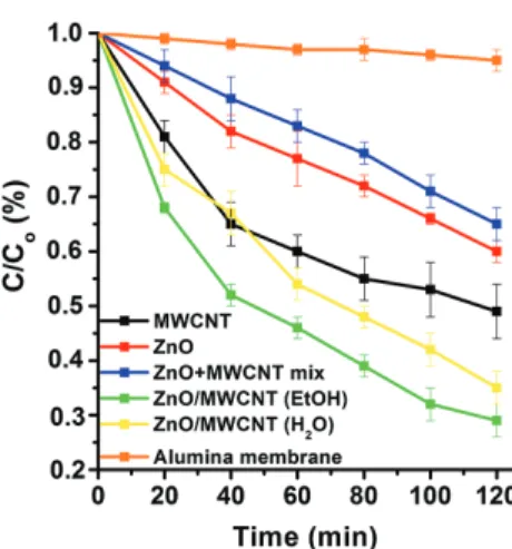
Figure 5. Photocatalytic decomposition of AA (cAA=0.9 mM;max
at 365 nm) by ZnO nanoparticles, MWCNT, pure alumina paper, the mechanic mixture of ZnO and MWCNT and ZnO/MWCNT nanocom- posites prepared in EtOH and H2O.
Furthermore, ZnO/MWNTs composite prepared in EtOH possesses the highest photocatalytic activity in the AA degradation reaction, which comes up to 71% in the AA photocatalysis processes. While by ZnO/MWCNT photo- catalyst, 71% (using EtOH as solvent—Fig. 5 green curve) and 65% (using H2O as solvent—Fig. 5 yellow curve) AA was decomposed after 120 minutes of irradiation, by ZnO-MWCNT mechanical mixture only 35% of AA was degraded after 120 minutes. Furthermore, it was found that the decomposition curve shape of pure MWCNT (Fig. 5—
black curve) is different from other curves, which is related to the great adsorption of AA by MWNTs because of high specific surface area (182.1 m2/g) and the tubular structure of MWNTs.17 Presumably, this can be a plausible expla- nation for higher photocatalytic activity of MWCNT com- pared to ZnO or the ZnO+MWCNT mechanical mixture.
4. CONCLUSION
ZnO nanoparticles were successfully coated on the surface of SDS modified MWCNT by a noncovalent impregnation method. It can be concluded that synthesis were successful in every case but the structure of the ZnO/MWCNT com- posites were different. Applying TEM technique it was verified that different layer construction and morphology can be obtained using EtOH and H2O as solvents. Products of impregnation method were ideal candidates as starting material in photocatalytic measurements due to the par- tially covered MWCNTs which are involved the adsorption process during photocatalysis.
As-prepared ZnO/MWCNT nanocomposites exhibit enhanced photocatalytic degradation property of AA, which is probably cause by electron transfer processes from the attached ZnO to MWCNT. It is known, carbon nanotubes are relatively good electron accep- tors,44 while semiconductor ZnO can be considered as good electron donor under UV illumination.9 Based on
ticles and the surface modified MWCNT in the as-prepared ZnO/MWCNT composites.
The synthesized ZnO/MWCNT nanocomposite prepared in EtOH showed the highest photocatalytic efficiency (71%) during the UV irradiated degradation of AA. The ZnO/MWCNT composites with good photoactivity would be promising for practical use in pollutant decomposition as an effective photocatalyst.
Acknowledgments: Special thanks to Professor László Forró and his research group in École Polytechnique Fédérale de Lausanne (EPFL) to provide us the multi- walled carbon nanotubes. This work was supported by grants from Switzerland through Swiss Contribution (SH/7/2/20). Zoltan Nemeth is very grateful for the finan- cial support by the ÚNKP-17-4-I-ME/12. New National Excellence Program of the Ministry of Human Capacities.
K. Hernadi acknowledges the financial support of GINOP- 2.3.2-15-2016-00013 project, too.
References and Notes
1. H. Chu, L. Wei, R. Cui, J. Wang, and Y. Li, Coord. Chem. Rev.
254, 1117(2010).
2. P. M. Ajayan and O. Z. Zhou,Appl. Phys. 80, 391(2001).
3. M. F. L. Volder, S. H. Tawfick, R. H. Baughman, and A. J. Hart, Science339, 535(2013).
4. C. W. Tan, K. H. Tan, Y. T. Ong, A. R. Mohamed, S. H. Zein, and S. H. Tan,Environ. Chem. Lett. 10, 265(2012).
5. Y. Sakata, M. A. Uddin, A. Muto, and M. Imaoka,Micropor. Mater.
9, 183(1997).
6. R. Das, S. B. A. Hamid, M. E. Ali, A. F. Ismail, M. S. M. Annuar, and S. Ramakrishna,Desalin.354, 160(2014).
7. T. A. Saleh and V. K. Gupta,Colloid. Interface Sci. 362, 337(2011).
8. J. E. Riggs, Z. Guo, D. L. Carroll, and Y.-P. Sun,J. Am. Chem. Soc.
122, 5897(2000).
9. V. Subramanian, E. E. Wolf, and P. V. Kamat,J. Am. Chem. Soc.
126, 4943(2004).
10. Q. Geng, Q. Guo, C. Cao, and L. Wang, Ind. Eng. Chem. Res.
47, 2561(2008).
11. B. Reti, K. Nemeth, Z. Nemeth, K. Mogyorosi, K. Marko, A. Erdohelyi, A. Dombi, and K. Hernadi, Phys. Stat. Sol. B 248, 2475(2011).
12. A. Jitinau, T. Cacciaguerra, R. Benoit, S. Delpeux, F. Béguin, and S. Bonnamy,Carbon42, 1147(2004).
13. V. M. Aroutiounian, V. M. Arakelyan, E. A. Khachaturyan, G. E.
Shahnararyan, M. S. Aleksanyan, L. Forro, A. Magrez, K. Hernadi, and Z. Nemeth,Sens. Act. B173, 890(2012).
IP: 193.22.15.105 On: Sat, 08 Dec 2018 13:11:52 Copyright: American Scientific Publishers
Delivered by Ingenta
14. J. Khanderi, C. Contiu, J. Engstler, R. C. Hoffmann, J. J. Schneider, A. Drochner, and H. Vogel,Nanoscale3, 1102(2011).
15. Y. Yu, L. Ma, W. Huang, F. Du, J. C. Yu, J. Yu, J. Wang, and P. K.
Wong,Carbon43, 670(2005).
16. L. P. Zhu, G. H. Liao, W. Y. Huang, L. L. Ma, Y. Yang, Y. Yu, and S. Y. Fu,Mat. Sci. Eng. B163, 194(2009).
17. L. Jiang and L. Gao,Mat. Chem. Phys.91, 313(2005).
18. X. Wang, B. Xia, X. Zhu, J. Chen, S. Qui, and J. Li,J. Sol. Stat.
Chem.181, 822(2008).
19. M. H. Huang, S. Mao, H. Feick, H. Q. Yan, Y. Y. Wu, H. Kind, E. Weber, R. Russo, and P. D. Yang,Science292, 1897(2001).
20. Z. L. Jiang, Z. X. Xie, X. H. Zhang, S. C. Lin, T. Xu, S. Y. Xie, R. B. Huang, and L. S. Zheng,Adv. Mater.16, 904(2004).
21. D. Yin, L. Zhang, B. Liu, and M. Wu,J. Nanosci. Nanotechol.
12, 937(2012).
22. S. A. Khayyat, M. Abaker, A. Umar, M. O. Alkattan, N. D. Alharbi, and S. Baskoutas,J. Nanosci. Nanotechnol.12, 8453(2012).
23. K. R. Lee, S. Park, K. W. Lee, and J. H. Lee,J. Mater. Sci. Lett.
22, 65(2003).
24. J. W. Liu, X. J. Li, and L. M. Dai,Adv. Mater.18, 1740(2006).
25. Y. W. Zhu, H. I. Elim, Y. L. Foo, T. Yu, Y. J. Liu, W. Ji, J. Y. Lee, Z. X. Shen, A. T. S. Wee, J. T. L. Thong, and C. H. Sow,Adv. Mater.
18, 587(2006).
26. M. Alaf, D. Gultekin, and H. Akbulut,Acta Phys. Pol. A125, 426 (2014).
27. Y. W. Koh, M. Lin, C. K. Tan, Y. L. Foo, and K. P. Loh,J. Phys.
Chem. B108, 11419(2004).
28. C. S. Chen, X. H. Chen, B. Yi, T. G. Liu, W. H. Li, L. S.
Xu, Z. Yang, H. Zhang, and Y. G. Wang,Acta Mater.54, 5401 (2006).
29. L. Fu, G. Lai, H. Zhang, and A. Yu, J. Nanosci. Nanotechnol.
15, 4325(2015).
30. E. A. Whitsitt and A. R. Barron,Nano Lett.3, 775(2002).
31. A. Di Crescenzo, V. Ettorre, and A. Fontana, Beilstein J. Nano- technol.5, 1675(2014).
32. L. Q. Jiang, L. Gao, and J. Sun,J. Colloid Interf. Sci.260, 89(2003).
33. P. Berki, Z. Nemeth, B. Reti, O. Berkesi, A. Magrez, V. Aroutiounian, L. Forro, and K. Hernadi,Carbon60, 266(2013).
34. Z. Nemeth, E. Horvath, A. Magrez, B. Reti, P. Berki, L. Forro, and K. Hernadi,Mat. Des.86, 198(2015).
35. E. Couteau, K. Hernadi, J. W. Seo, L. Thien-Nga, Cs. Miko, R. Gaal, and L. Forro,Chem. Phys. Lett.378, 9(2003).
36. A. Magrez, J. W. Seo, Cs. Miko, K. Hernadi, and L. Forro,J. Phys.
Chem. B109, 10087(2005).
37. R. Smajda, M. Mionic, M. Duchamo, J. C. Anderson, and L. Forro, Phys. Stat. Sol. C7, 1236(2010).
38. S. Brunauer, P. H. Emett, and E. Teller,J. Am. Chem. Soc.60, 309 (1938).
39. http://www.cotronics.com/vo/cotr/pdf/300.pdf.
40. C. L. Bianchi, S. Gatto, C. Pirola, A. Naldoni, A. Di Michele, G. Cerrato, V. Crocella, and V. Capucci,Appl. Catal. B: Environ.
146, 123(2014).
41. B. S. Ong, L. Chensha, L. Yuning, Y. Wu, and R. Loutfy,J. Am.
Chem. Soc.129, 2750(2007).
42. A. L. Patterson,Phys. Rev.56 978(1939).
43. J. Yang, B. Wei, X. Li, J. Wang, H. Zhai, X. Li, Y. Sui, Y. Liu, J. Wang, J. Lang, and Q. Zhang,Crystal Res. Tech.50, 840(2015).
44. Y. Sun, S. R. Wilson, and D. I. Schuster, J. Am. Chem. Soc.
123, 5348(2001).
45. J. Sun, L. Gao, and M. Iwasa,Chem. Commun.7, 832(2004).
Received: 26 September 2017. Accepted: 20 February 2018.