Article
Photocatalytic and Gas Sensitive Multiwalled Carbon Nanotube / TiO 2 -ZnO and ZnO-TiO 2 Composites
Prepared by Atomic Layer Deposition
LászlóPéter Bakos1,* , Nóra Justh1, Ulisses Carlo Moura da Silva Bezerra da Costa1, Krisztina László2 , János LászlóLábár3 , Tamás Igricz4, Katalin Varga-Josepovits5, Pawel Pasierb6, Elina Färm7, Mikko Ritala8, Markku Leskelä8 and Imre Miklós Szilágyi1
1 Department of Inorganic and Analytical Chemistry, Budapest University of Technology and Economics, Szent Gellért tér 4., H-1111 Budapest, Hungary; justh.nora@gmail.com (N.J.);
ulissesccosta@gmail.com (U.C.M.d.S.B.d.C.); imre.szilagyi@mail.bme.hu (I.M.S.)
2 Department of Physical Chemistry and Materials Science,
Budapest University of Technology and Economics, P.O. Box 92, H-1521 Budapest, Hungary;
klaszlo@mail.bme.hu
3 Institute for Technical Physics and Materials Science, Research Centre of Energy, Hungarian Academy of Sciences, Konkoly–Thegeút 29–33., H-1121 Budapest, Hungary;
labar.janos@energia.mta.hu
4 Department of Organic Chemistry and Technology, Budapest University of Technology and Economics, Budafokiút 8., H-1111 Budapest, Hungary; igricz.tamas@gmail.com
5 Department of Atomic Physics, Budapest University of Technology and Economics, Budafokiút 8., H-1111 Budapest, Hungary; flip@eik.bme.hu
6 Department of Inorganic Chemistry, AGH University of Science and Technology, Mickiewicza 30., 30-059 Kraków, Poland; ppasierb@agh.edu.pl
7 ASM Microchemistry Oy, Pietari Kalmin katu 1F2, FI-00560 Helsinki, Finland; elina.farm@helsinki.fi
8 Department of Chemistry, University of Helsinki, P.O. Box 55, FI-00014 Helsinki, Finland;
mikko.ritala@helsinki.fi (M.R.); markku.leskela@helsinki.fi (M.L.)
* Correspondence: laszlobakos@hotmail.com
Received: 5 December 2019; Accepted: 23 January 2020; Published: 31 January 2020
Abstract: TiO2 and ZnO single and multilayers were deposited on hydroxyl functionalized multi-walled carbon nanotubes using atomic layer deposition. The bare carbon nanotubes and the resulting heterostructures were characterized by TG/DTA, Raman, XRD, SEM-EDX, XPS, TEM-EELS-SAED and low temperature nitrogen adsorption techniques, and their photocatalytic and gas sensing activities were also studied. The carbon nanotubes (CNTs) were uniformly covered with anatase TiO2and wurtzite ZnO layers and with their combinations. In the photocatalytic degradation of methyl orange, the most beneficial structures are those where ZnO is the external layer, both in the case of single and double oxide layer covered CNTs (CNT-ZnO and CNT-TiO2-ZnO). The samples with multilayer oxides (CNT-ZnO-TiO2and CNT-TiO2-ZnO) have lower catalytic activity due to their larger average densities, and consequently lower surface areas, compared to single oxide layer coated CNTs (CNT-ZnO and CNT-TiO2). In contrast, in gas sensing it is advantageous to have TiO2as the outer layer. Since ZnO has higher conductivity, its gas sensing signals are lower when reacting with NH3gas. The double oxide layer samples have higher resistivity, and hence a larger gas sensing response than their single oxide layer counterparts.
Keywords: carbon nanotubes; titanium dioxide; zinc oxide; atomic layer deposition; photocatalysis;
gas sensing
Nanomaterials2020,10, 252; doi:10.3390/nano10020252 www.mdpi.com/journal/nanomaterials
Nanomaterials2020,10, 252 2 of 14
1. Introduction
Carbon nanotubes (CNTs) have attracted great interest for application in diverse fields owing to their unique chemical and physical properties. These fields include conductive and high-strength composites, energy storage and energy conversion devices, sensors, field emission displays and radiation sources, hydrogen storage media and heterogeneous catalysis [1–11]. TiO2and ZnO are widely researched materials in various areas, including photocatalytic wastewater treatment and hydrogen production, solar cells and gas sensing [12–21]. CNTs have been successfully used as catalyst support materials. As photocatalyst carriers they can increase the separation and migration of photogenerated electrons and holes [22–24]. Carbon nanotubes and semiconducting metal oxides have been studied in gas sensing applications, because adsorption and desorption of gas molecules on the surface results in charge transfer, which leads to change in electric resistance. The detection sensitivity to gases depends on many factors; e.g., grain size, surface composition and morphology and the target gas [25–31].
CNT-TiO2and CNT-ZnO composites can be prepared by various methods; e.g., hydrothermal synthesis, sputtering, chemical vapor deposition (CVD) and atomic layer deposition (ALD) [32–34].
Among them, ALD has the advantage that it allows the coating of nanostructures in a conformal and homogenous way, with a precise control of the thickness of the deposited film at the nanoscale by successive, self-terminating, gas–surface half-reactions [35–41].
Different metal oxides were already deposited on CNTs by ALD, e.g., Al2O3, SnO2, V2O4, HfO2, Fe2O3, TiO2and ZnO, and in some cases they were studied in gas sensing or photocatalysis applications [42–47]. Previously, it was also studied how changing the core and shell materials influence the photocatalytic activity and gas sensing properties of TiO2-ZnO and ZnO-TiO2core-shell nanofibers prepared by electrospinning and ALD [48,49]. However, to the best of our knowledge, multilayer oxide coatings have not been grown on CNTs to obtain photocatalytic and gas sensitive core-shell nanocomposites.
In our research, ALD TiO2and ZnO metal oxide layers were grown on multi-walled CNTs, which were functionalized with hydroxyl groups (CNT-OH) serving as ALD nucleation sites. Both single and double oxide layer coated CNT composites, i.e., CNT-TiO2and CNT-ZnO, and CNT-TiO2-ZnO and CNT-ZnO-TiO2samples, were obtained. The name indicates the sequence of the oxide ALD processes.
The carbon nanotubes and the resulting CNT-metal oxide composite materials were characterized using TG/DTA, Raman spectroscopy, XRD, XPS, SEM-EDX, TEM-EELS-SAED and low temperature N2
adsorption. Finally, the activities of the as-prepared samples as photocatalysts and NH3gas sensors were studied.
2. Materials and Methods
2.1. Sample Preparation
Hydroxyl functionalized multi-walled carbon nanotubes with external diameters of 30–50 nm were used as obtained (Cheap Tubes, Cambridgeport, VT, USA).
Atomic layer deposition of TiO2and ZnO was performed in an ASM F-120 ALD reactor by the reaction of TiCl4and (C2H5)2Zn with H2O, respectively. The reactor was operated at a pressure of about 5 mbar using nitrogen as the carrier and purge gas. For one batch, 50 mg substrate powder was placed in a folded steel mesh into the reactor. The parameters of the ALD processes are summarized in Table1. Each time, 12 nm thick films were grown. The thicknesses were approximated by X-ray reflectometry (Bruker D8 Advance) on Si reference wafers that were coated together with CNTs.
Table 1.ALD process parameters.
Deposited
Oxide Temperature/◦C Number of Cycles
Pulse Times/s
Metallic Precursor N2Purge Water N2Purge
TiO2 250 250 1.5 30 3 30
ZnO 200 120 3 30 3 30
2.2. Characterization
The details of the instruments and characterization methods used can be found in the Supplementary Materials. TG/DTA curves were measured in inert (N2) and oxidizing (air) conditions with a linear temperature program (10◦C min−1). To get structure data, Raman, XRD and SAED studies were done. To see the morphologies of the samples, SEM and TEM images were taken. The elemental compositions and bonding states and were investigated with XPS, EDX and EELS. Nitrogen adsorption was utilized to measure the specific surface area. The photocatalytic activity was investigated by decomposing an aqueous solution of methyl orange under UV light irradiation (spectrum: Figure S1), and P25 Degussa TiO2was used for reference material. NH3gas sensing properties were tested at different concentrations and temperatures (setup: Figures S27–S28).
3. Results and Discussion
3.1. TG/DTA
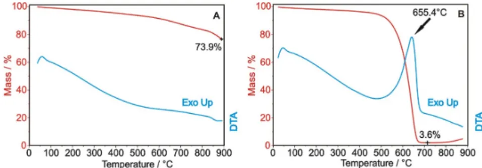
From the thermal analysis in nitrogen (Figure1A), it can be seen that the bare OH-functionalized carbon nanotubes lose 26.1% of the initial mass, accompanied by an endothermic process. The decomposition is not significant at the early stages; thus, the ALD process can be safely performed at 200◦C for ZnO and at 250◦C for TiO2without damaging the carbon nanotube substrates. In Figure1B, the thermal analysis in air shows that the exothermic combustion of the carbon nanotubes starts around 500◦C, leaving only 3.6% residual mass at 700◦C. The residue is the catalyst used for CNT preparation, which upon further annealing in air at 900◦C gets oxidized.
Nanomaterials 2020, 10, x FOR PEER REVIEW 3 of 15
2.2. Characterization
The details of the instruments and characterization methods used can be found in the Supplementary Materials. TG/DTA curves were measured in inert (N2) and oxidizing (air) conditions with a linear temperature program (10 °C min−1). To get structure data, Raman, XRD and SAED studies were done. To see the morphologies of the samples, SEM and TEM images were taken. The elemental compositions and bonding states and were investigated with XPS, EDX and EELS.
Nitrogen adsorption was utilized to measure the specific surface area. The photocatalytic activity was investigated by decomposing an aqueous solution of methyl orange under UV light irradiation (spectrum: Figure S1), and P25 Degussa TiO2 was used for reference material. NH3 gas sensing properties were tested at different concentrations and temperatures (setup: Figures S27–S28).
3. Results and Discussion
3.1. TG/DTA
From the thermal analysis in nitrogen (Figure 1A), it can be seen that the bare OH-functionalized carbon nanotubes lose 26.1% of the initial mass, accompanied by an endothermic process. The decomposition is not significant at the early stages; thus, the ALD process can be safely performed at 200 °C for ZnO and at 250 °C for TiO2 without damaging the carbon nanotube substrates. In Figure 1B, the thermal analysis in air shows that the exothermic combustion of the carbon nanotubes starts around 500 °C, leaving only 3.6% residual mass at 700 °C. The residue is the catalyst used for CNT preparation, which upon further annealing in air at 900 °C gets oxidized.
Figure 1. TG/DTA measurements of the OH-functionalized carbon nanotubes in nitrogen (A) and air atmospheres (B).
3.2. Raman Spectroscopy
The D and G peaks of the carbon are present in all samples (Figure 2). In the TiO2 containing samples, the most intensive additional band is the TiO2 (anatase) at 141 cm−1. The further characteristic peaks of TiO2 at 400, 516 and 637 cm−1 are the most obvious in the CNT-TiO2 sample [50]. The bands of the ZnO are also detectable at 320, 428 and 569 cm−1, but they are much weaker compared to the TiO2 signals. The presence of both TiO2 and ZnO was also verified later by XRD. In the CNT-double oxide samples both oxide signals show a reduced intensity compared with the CNTs coated by any of the single oxide layers.
Figure 1.TG/DTA measurements of the OH-functionalized carbon nanotubes in nitrogen (A) and air atmospheres (B).
3.2. Raman Spectroscopy
The D and G peaks of the carbon are present in all samples (Figure2). In the TiO2containing samples, the most intensive additional band is the TiO2(anatase) at 141 cm−1. The further characteristic peaks of TiO2at 400, 516 and 637 cm−1are the most obvious in the CNT-TiO2sample [50]. The bands of the ZnO are also detectable at 320, 428 and 569 cm−1, but they are much weaker compared to the TiO2signals. The presence of both TiO2and ZnO was also verified later by XRD. In the CNT-double oxide samples both oxide signals show a reduced intensity compared with the CNTs coated by any of the single oxide layers.
Nanomaterials2020,10, 252 4 of 14
Nanomaterials 2020, 10, x FOR PEER REVIEW 4 of 15
Figure 2. Raman spectra of the samples.
3.3. Powder XRD
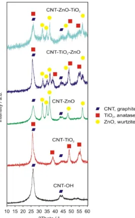
XRD diffractograms (Figure 3) confirm the presence of the semiconductor oxides deposited on the carbon nanotubes. In the case of the bare carbon nanotubes, the peaks are characteristic of the rolled graphite layers in the multiwalled CNTs (ICDD 01-71-4630). The as-grown oxide materials are crystalline; i.e., TiO2 is present as the anatase (ICDD 01-075-2546), and ZnO as the wurtzite (ICDD 01- 080-4199), corroborating Raman spectra. Similarly to the Raman results, the oxide signals are weaker in the case of the double oxide layer coatings, than in the single oxide layer coated samples. This might imply an interaction, e.g., interdiffusion between the oxide layers, which may occur during the ALD growth of the second oxide layer. This could reduce the crystalline order of the layers, and thus, the XRD and Raman peak intensities.
Figure 2.Raman spectra of the samples.
3.3. Powder XRD
XRD diffractograms (Figure3) confirm the presence of the semiconductor oxides deposited on the carbon nanotubes. In the case of the bare carbon nanotubes, the peaks are characteristic of the rolled graphite layers in the multiwalled CNTs (ICDD 01-71-4630). The as-grown oxide materials are crystalline; i.e., TiO2is present as the anatase (ICDD 01-075-2546), and ZnO as the wurtzite (ICDD 01-080-4199), corroborating Raman spectra. Similarly to the Raman results, the oxide signals are weaker in the case of the double oxide layer coatings, than in the single oxide layer coated samples. This might imply an interaction, e.g., interdiffusion between the oxide layers, which may occur during the ALD growth of the second oxide layer. This could reduce the crystalline order of the layers, and thus, the XRD and Raman peak intensities.
Nanomaterials 2020, 10, x FOR PEER REVIEW 5 of 15
Figure 3. XRD diffractograms of the samples and the assignation of the peaks.
3.4. SEM and TEM
Figure 4 portraits SEM images of the samples after the ALD processes. The as-grown oxide layers are clearly visible on the surface of the CNTs. In the ALD reactions, both ZnO and TiO2 nucleate as grains, and then coalesce to form a continuous layer. Since ZnO crystallizes easier than TiO2 during the ALD depositions, it seems to form larger grains than TiO2. In the case of the double oxide layers, the oxide coating on the CNTs becomes thicker and smoother. Based on the resolution of the SEM images, the smoothest surface was obtained in the CNT-ZnO-TiO2 sample. The approximate diameters for the samples were around 35 nm for the CNT-OH, 50 nm for the CNT-TiO2 and 70 nm for all the other composites.
Figure 3.XRD diffractograms of the samples and the assignation of the peaks.
3.4. SEM and TEM
Figure4portraits SEM images of the samples after the ALD processes. The as-grown oxide layers are clearly visible on the surface of the CNTs. In the ALD reactions, both ZnO and TiO2nucleate as grains, and then coalesce to form a continuous layer. Since ZnO crystallizes easier than TiO2during the ALD depositions, it seems to form larger grains than TiO2. In the case of the double oxide layers, the oxide coating on the CNTs becomes thicker and smoother. Based on the resolution of the SEM images, the smoothest surface was obtained in the CNT-ZnO-TiO2sample. The approximate diameters for the samples were around 35 nm for the CNT-OH, 50 nm for the CNT-TiO2and 70 nm for all the other composites.
Nanomaterials 2020, 10, x FOR PEER REVIEW 6 of 15
Figure 4. SEM images of the samples. In the white frame, the SEM picture of an uncoated CNT-OH is shown at the same magnification for reference.
The TEM images of the CNT-TiO2 and the CNT-ZnO samples (Figure 5A and Figure 5C, respectively) reveal the metal oxide layers composed of oxide nanoparticles on the carbon nanotubes.
The electron diffraction patterns of the CNT-TiO2 (Figure 5B) and CNT-ZnO (Figure 5D) samples corroborate the XRD and Raman measurements, revealing that the oxides are present as anatase and wurtzite, respectively. The TEM images of the double oxide layer coated samples (Figure 5E–I) show again that the CNTs have thicker oxide shells. The EELS maps of the C, Ti and Zn of the CNT-TiO2- ZnO and CNT-ZnO-TiO2 samples present the carbon core morphology surrounded by the Ti and Zn oxide layers. It is shown that the oxide layers cover the CNTs uniformly.
Figure 4.SEM images of the samples. In the white frame, the SEM picture of an uncoated CNT-OH is shown at the same magnification for reference.
The TEM images of the CNT-TiO2and the CNT-ZnO samples (Figures5A and5C, respectively) reveal the metal oxide layers composed of oxide nanoparticles on the carbon nanotubes. The electron diffraction patterns of the CNT-TiO2 (Figure5B) and CNT-ZnO (Figure5D) samples corroborate the XRD and Raman measurements, revealing that the oxides are present as anatase and wurtzite, respectively. The TEM images of the double oxide layer coated samples (Figure5E–I) show again that the CNTs have thicker oxide shells. The EELS maps of the C, Ti and Zn of the CNT-TiO2-ZnO and CNT-ZnO-TiO2samples present the carbon core morphology surrounded by the Ti and Zn oxide layers. It is shown that the oxide layers cover the CNTs uniformly.
Nanomaterials2020,10, 252 6 of 14
Nanomaterials 2020, 10, x FOR PEER REVIEW 7 of 15
Figure 5.TEM (A) and FFT (B) of images of the CNT-TiO2sample; TEM (C) and FFT (D) of images of the CNT-ZnO sample; TEM (E) image and C (F), Ti (G) and Zn (H) EELS maps of the CNT-TiO2-ZnO sample; TEM (I) image and C (J), Ti (K) and Zn (L) EELS maps of the CNT-ZnO-TiO2sample.The FFT of a TEM image has the same informational content as a SAED pattern (and is similar in appearance) from the same area.
3.5. EDX and XPS
EDX and XPS measurements also confirm that the deposition of semiconductor oxide layers was successful in the case of all samples (Table2and Figures S2–S27). The XPS energies of 2p3/2peaks in all samples at 459.4 eV and at 1024.0 eV for the Ti and Zn, respectively, indicate that they are present as TiO2and ZnO [51,52].
Table 2.Elemental composition from EDX and XPS measurements.
Sample
EDX XPS
Atomic %
C O Ti Zn C O Ti Zn
CNT-OH 96.0 4.0 96.3 3.7
CNT-TiO2 82.0 16.2 1.8 74.7 18.8 6.5
CNT-ZnO 92.2 7.0 0.7 82.4 8.6 9.0
CNT-TiO2-ZnO 73.5 21.1 4.8 0.5 71.1 16.7 5.0 7.2
CNT-ZnO-TiO2 58.2 34.3 6.6 0.9 60.0 26.2 8.4 5.4
These two methods complement each other, as XPS provides information mainly about the top 5–10 nm layer, while the information depth of EDX is ca. 0.5–1µm. That is, XPS provides data about the very surface of the composites, and EDX, rather, about the bulk average. Accordingly, XPS measures 5−10 times higher concentration for Ti and Zn present on the surface of the CNT-oxide composite samples than EDX.
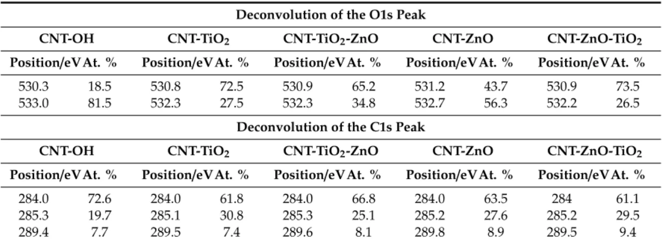
Based on the peak deconvolution (Table3), the O1s peak of the bare CNT-OH sample contains the oxygen in two different states; i.e., the peak at 530.3 eV corresponds to the oxygen in physically adsorbed water and possible surface carbonate/carboxyl groups, while the peak at 533.0 eV is the oxygen in the OH group and chemisorbed water. The O1s peak of the coated samples at 530.8−531.2 eV comes mostly from the oxygen in the metal oxides. Compared to the bare CNT-OH, the intensity of this peak increases gradually when single and double oxide layers are grown, and simultaneously, the intensity of the OH peak between 532.2 and 532.7 decreases because the ALD reactions use up a significant amount of the OH groups [48].
Table 3.Deconvolutions of the O1s and the C1s peaks from XPS measurements.
Deconvolution of the O1s Peak
CNT-OH CNT-TiO2 CNT-TiO2-ZnO CNT-ZnO CNT-ZnO-TiO2
Position/eVAt. % Position/eVAt. % Position/eVAt. % Position/eVAt. % Position/eVAt. %
530.3 18.5 530.8 72.5 530.9 65.2 531.2 43.7 530.9 73.5
533.0 81.5 532.3 27.5 532.3 34.8 532.7 56.3 532.2 26.5
Deconvolution of the C1s Peak
CNT-OH CNT-TiO2 CNT-TiO2-ZnO CNT-ZnO CNT-ZnO-TiO2
Position/eVAt. % Position/eVAt. % Position/eVAt. % Position/eVAt. % Position/eVAt. %
284.0 72.6 284.0 61.8 284.0 66.8 284.0 63.5 284 61.1
285.3 19.7 285.1 30.8 285.3 25.1 285.2 27.6 285.2 29.5
289.4 7.7 289.5 7.4 289.6 8.1 289.8 8.9 289.5 9.4
Carbon is present in three different forms. The peak at 284.0 eV corresponds to the C–C bond, while the peak between 285.1 and 285.3 eV is related to structural defects, attributed to C atoms no longer in the regular tubular structure. The ratio of the defect related carbon increases after the ALD reactions, while the intensity of the C–C peak decreases. The signal in the 289.4−289.8 eV range is
Nanomaterials2020,10, 252 8 of 14
related to the bond between C and O. Its intensity does not change significantly after the ALD processes, since most of the C–OH moieties are replaced by C–O–metal bonds [53].
3.6. Nitrogen Adsorption
The surface areas from the nitrogen adsorption measurements are shown in Table4. The bare CNT-OH has the largest apparent surface area. After coating with a single metal oxide layer, its value decreases, and by applying a second layer, it decreases further. As the densities of the deposited oxides are significantly greater than that of the carbon nanotubes, after the ALD film growth, the average density of each sample increases. This is partly responsible for the decreasing specific surface area.
Table 4.The measurements of the specific surface areas of the samples.
Sample CNT-OH CNT-TiO2 CNT-ZnO CNT-TiO2-ZnO CNT-ZnO-TiO2
SBET/m2g−1 94 54 75 43 31
3.7. Photocatalysis
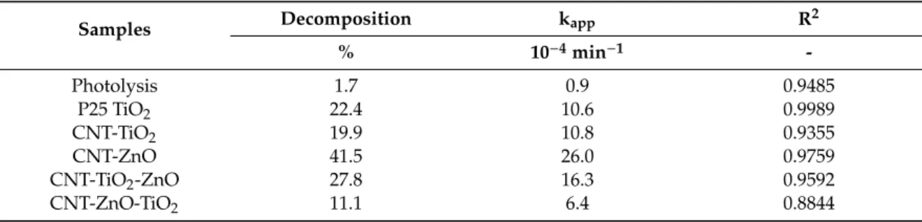
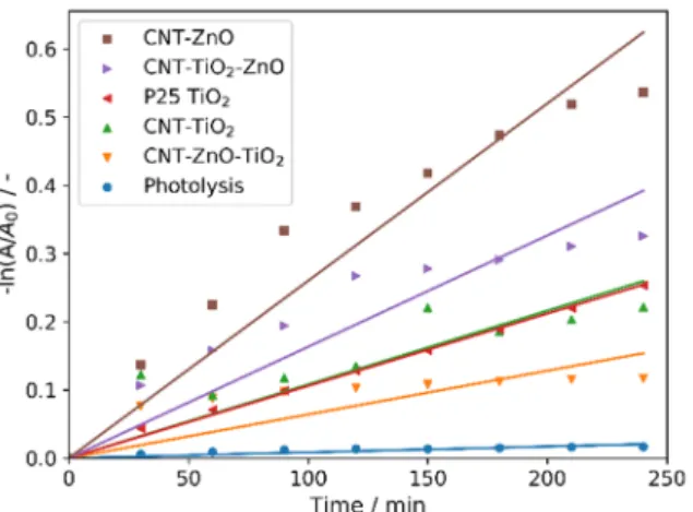
All CNT-metal oxide composites possess photocatalytic activity—decomposing methyl orange (Figures6and7). The CNT-ZnO sample has the best photocatalytic performance, also confirmed by the apparent reaction rate constants of the photocatalysis (Table5) [46]. Compared to this, a significantly lower activity was observed when CNTs were coated with a TiO2layer. When the second oxide layers are grown onto the CNT-single oxide layer composites, the photocatalytic activity decreases in the case of both CNT-ZnO and CNT-TiO2substrates. The reason for this is that when the amount of heavier oxides increases compared to the lighter carbon core, the average density increases, and the surface area introduced by the 1 mg catalyst sample into the photocatalytic tests is decreased. In the case of the double layered samples, the photocatalytic results are better when ZnO is the outer layer. This is in line with the observation that the CNT-ZnO is a better photocatalyst than CNT-TiO2. In fact, even the CNT-TiO2-ZnO sample has higher activity than the CNT-TiO2sample.
Nanomaterials 2020, 10, x FOR PEER REVIEW 9 of 15
Table 3. Deconvolutions of the O1s and the C1s peaks from XPS measurements.
Deconvolution of the O1s Peak
CNT-OH CNT-TiO2 CNT-TiO2-ZnO CNT-ZnO CNT-ZnO-TiO2
Position/eV At. % Position/eV At. % Position/eV At. % Position/eV At. % Position/eV At. % 530.3 18.5 530.8 72.5 530.9 65.2 531.2 43.7 530.9 73.5 533.0 81.5 532.3 27.5 532.3 34.8 532.7 56.3 532.2 26.5
Deconvolution of the C1s Peak
CNT-OH CNT-TiO2 CNT-TiO2-ZnO CNT-ZnO CNT-ZnO-TiO2
Position/eV At. % Position/eV At. % Position/eV At. % Position/eV At. % Position/eV At. % 284.0 72.6 284.0 61.8 284.0 66.8 284.0 63.5 284 61.1 285.3 19.7 285.1 30.8 285.3 25.1 285.2 27.6 285.2 29.5 289.4 7.7 289.5 7.4 289.6 8.1 289.8 8.9 289.5 9.4
3.6. Nitrogen Adsorption
The surface areas from the nitrogen adsorption measurements are shown in Table 4. The bare CNT-OH has the largest apparent surface area. After coating with a single metal oxide layer, its value decreases, and by applying a second layer, it decreases further. As the densities of the deposited oxides are significantly greater than that of the carbon nanotubes, after the ALD film growth, the average density of each sample increases. This is partly responsible for the decreasing specific surface area.
Table 4. The measurements of the specific surface areas of the samples.
Sample CNT-OH CNT-TiO2 CNT-ZnO CNT-TiO2-ZnO CNT-ZnO-TiO2
SBET/m2 g−1 94 54 75 43 31
3.7. Photocatalysis
All CNT-metal oxide composites possess photocatalytic activity—decomposing methyl orange (Figure 6-7). The CNT-ZnO sample has the best photocatalytic performance, also confirmed by the apparent reaction rate constants of the photocatalysis (Table 5) [46]. Compared to this, a significantly lower activity was observed when CNTs were coated with a TiO2 layer. When the second oxide layers are grown onto the CNT-single oxide layer composites, the photocatalytic activity decreases in the case of both CNT-ZnO and CNT-TiO2 substrates. The reason for this is that when the amount of heavier oxides increases compared to the lighter carbon core, the average density increases, and the surface area introduced by the 1 mg catalyst sample into the photocatalytic tests is decreased. In the case of the double layered samples, the photocatalytic results are better when ZnO is the outer layer.
This is in line with the observation that the CNT-ZnO is a better photocatalyst than CNT-TiO2. In fact, even the CNT-TiO2-ZnO sample has higher activity than the CNT-TiO2 sample.
Figure 6. Photocatalytic activities of the samples.
Figure 6.Photocatalytic activities of the samples.
Table 5.Results of the photocatalytic experiments.
Samples Decomposition kapp R2
% 10−4min−1 -
Photolysis 1.7 0.9 0.9485
P25 TiO2 22.4 10.6 0.9989
CNT-TiO2 19.9 10.8 0.9355
CNT-ZnO 41.5 26.0 0.9759
CNT-TiO2-ZnO 27.8 16.3 0.9592
CNT-ZnO-TiO2 11.1 6.4 0.8844
Figure 7. Pseudo first order linear fitting of the photocatalysis.
Table 5. Results of the photocatalytic experiments.
Samples Decomposition kapp R2
% 10−4 min−1 -
Photolysis 1.7 0.9 0.9485
P25 TiO2 22.4 10.6 0.9989
CNT-TiO2 19.9 10.8 0.9355
CNT-ZnO 41.5 26.0 0.9759
CNT-TiO2-ZnO 27.8 16.3 0.9592
CNT-ZnO-TiO2 11.1 6.4 0.8844
In case of the monolayer coated samples, the CNT core as an electron acceptor serves as a sink for the photogenerated electrons, while the holes stay in the metal oxides. This process slows the electron-hole recombination rate, thereby increasing the photocatalytic activity, as the holes can initialize the radical formation more efficiently compared to the bare metal oxides. Moreover, the metal–oxygen–carbon bonds act as sensitizers by narrowing the band gap [54,55]. Despite these effects, CNT-TiO2 still performed worse than the reference P25 TiO2, while CNT-ZnO was by far the most effective photocatalyst. For the double-layer coated composites, the obtained results correspond to former studies on ZnO-TiO2 and TiO2-ZnO core/shell nanofibers prepared by electrospinning and ALD [48,56]. The electron-hole pairs are generated mainly in the shell layers under illumination; the holes prefer the ZnO while the electrons migrate to the TiO2. For photocatalysis the outer layer is more important, since it is in physical contact with the material to be decomposed. Therefore, photogenerated electrons are mostly responsible for the photocatalytic activity in the case of the CNT- ZnO-TiO2 composite, while the photocatalysis in the presence of the CNT-TiO2-ZnO composite is controlled by the holes. To generate reactive species, the electrons have to react with oxygen, which is not abundant in the solution, while the holes react with water to produce OH radicals; thus, the ZnO outer layer is preferred. Based on previous results and our present results, higher photocatalytic activity is observed when ZnO is the outer layer than with TiO2 being the outer one, and it is even higher than with the conventional P25 reference TiO2. This can be explained by the surface chemistry and the intrinsic characteristics of the photogenerated charge carriers. The amount of the chemisorbed oxygen at the lattice defect sites (532.3 eV peak on XPS, Table 3) for CNT-TiO2-ZnO is 1.3 times higher than for the CNT-ZnO-TiO2. ZnO may enhance the hole capture process through O defects, resulting in a lower binding energy for adsorbates, and a comparatively lower mobility of the holes in its valence band.
3.8. Gas Sensing
The gas sensing results are shown in Figure 8. An n-type NH3 gas response is visible in all cases.
The gas sensing activity is better with all samples at 25 °C than at 150 °C, because the conductivity of the semiconductors layers increases with temperature, and hence the gas responses are lower. There
Figure 7.Pseudo first order linear fitting of the photocatalysis.
In case of the monolayer coated samples, the CNT core as an electron acceptor serves as a sink for the photogenerated electrons, while the holes stay in the metal oxides. This process slows the electron-hole recombination rate, thereby increasing the photocatalytic activity, as the holes can initialize the radical formation more efficiently compared to the bare metal oxides. Moreover, the metal–oxygen–carbon bonds act as sensitizers by narrowing the band gap [54,55]. Despite these effects, CNT-TiO2still performed worse than the reference P25 TiO2, while CNT-ZnO was by far the most effective photocatalyst. For the double-layer coated composites, the obtained results correspond to former studies on ZnO-TiO2and TiO2-ZnO core/shell nanofibers prepared by electrospinning and ALD [48,56]. The electron-hole pairs are generated mainly in the shell layers under illumination;
the holes prefer the ZnO while the electrons migrate to the TiO2. For photocatalysis the outer layer is more important, since it is in physical contact with the material to be decomposed. Therefore, photogenerated electrons are mostly responsible for the photocatalytic activity in the case of the CNT-ZnO-TiO2composite, while the photocatalysis in the presence of the CNT-TiO2-ZnO composite is controlled by the holes. To generate reactive species, the electrons have to react with oxygen, which is not abundant in the solution, while the holes react with water to produce OH radicals; thus, the ZnO outer layer is preferred. Based on previous results and our present results, higher photocatalytic activity is observed when ZnO is the outer layer than with TiO2being the outer one, and it is even higher than with the conventional P25 reference TiO2. This can be explained by the surface chemistry and the intrinsic characteristics of the photogenerated charge carriers. The amount of the chemisorbed oxygen at the lattice defect sites (532.3 eV peak on XPS, Table3) for CNT-TiO2-ZnO is 1.3 times higher than for the CNT-ZnO-TiO2. ZnO may enhance the hole capture process through O defects, resulting in a lower binding energy for adsorbates, and a comparatively lower mobility of the holes in its valence band.
3.8. Gas Sensing
The gas sensing results are shown in Figure8. An n-type NH3gas response is visible in all cases.
The gas sensing activity is better with all samples at 25◦C than at 150◦C, because the conductivity of the semiconductors layers increases with temperature, and hence the gas responses are lower. There are small delays in the responses and recoveries for all samples at all detected gas concentrations due to the gas sensing setup volume.
Nanomaterials2020,10, 252 10 of 14
Nanomaterials 2020, 10, x FOR PEER REVIEW 11 of 15
are small delays in the responses and recoveries for all samples at all detected gas concentrations due to the gas sensing setup volume.
Figure 8.NH3gas sensing measurements of the various samples.
Figure 8.NH3gas sensing measurements of the various samples.
The CNT-OH sample shows a small sensitivity at room temperature, which becomes even lower at 150◦C. When ZnO is deposited on the CNTs, the surface conductivity seems to increase, which is
reflected by the decreased base resistivity, and also by the fact that that hardly any gas sensing signal is observed for this sample, even at 25◦C. When CNTs are covered with a single layer of TiO2by ALD, the room temperature response increases compared to that with CNT-OH, and the gas sensing property is also more pronounced at 150◦C. The resistivity of the ALD TiO2is often low [57,58]. Unlike the single layer oxide coatings, the CNT-multilayer oxide composites have a considerably better gas sensing performance, due to the increased resistivity of the thicker oxide shells. Because of the two layers, there is contact resistance between them, the coverage is smoother and there are less holes in the coating. In the case of these samples, it is also obvious that the order of the layers has a significant impact on the gas sensing properties. When TiO2is the outer layer, the response is around forty times greater at both temperatures, compared to when ZnO is the outer layer. This is explained by the lower conductivity of TiO2compared to ZnO. The interaction with the NH3gas results in a larger change in its surface resistance [59]. Therefore, in contrast to photocatalysis, for which a ZnO outer layer is more beneficial, in the case of gas sensing, it is preferable to have TiO2as the outer layer.
4. Conclusions
TiO2and ZnO single and multilayers have been successfully deposited on hydroxyl functionalized multi-walled carbon nanotubes. CNT-TiO2, CNT-ZnO, CNT-TiO2-ZnO and CNT-ZnO-TiO2core/shell nanocomposites are obtained. TG/DTA curves reveal that CNT-OH is thermally stable at the ALD temperatures; i.e., at 250◦C and 200 for TiO2and ZnO, respectively. EDX, XPS and Raman spectroscopy confirm the presence of the deposited oxides on the CNTs. The as-grown metal oxide layers are crystalline; i.e., TiO2is present as anatase and ZnO as wurtzite. SEM and TEM images show that the TiO2and ZnO nucleate as particles on CNTs, which merge to form uniform and continuous layers.
Due to the presence of heavier oxide coating on the lighter carbon cores, the specific surface area of the nanocomposites decreases compared to the bare CNT-OH sample. The composites possess significant photocatalytic activity in decomposing methyl orange dye under UV light irradiation. The most beneficial structure is when ZnO is the outer layer, both in the case of single and double oxide layer covered CNTs. The samples with multilayer oxides have lower activity due to their larger average density and lower specific surface area. In contrast to photocatalysis, in gas sensing the advantageous structure is the one where TiO2is the outer layer, since ZnO has higher conductivity, and thus, its gas-sensing signals are lower than those of TiO2when interacting with NH3gas. Both the resistivity and the gas sensing signals are higher in multilayer oxide coated CNTs than either in CNT-TiO2 or CNT-ZnO.
Supplementary Materials: The following are available online athttp://www.mdpi.com/2079-4991/10/2/252/s1:
Instruments used for the characterization; UV–Vis spectrum of the lamps used; EDX and XPS spectra of the samples; setup used for the gas sensing experiments.
Author Contributions: Conceptualization, M.R., M.L. and I.M.S.; funding acquisition, M.L. and I.M.S.;
investigation, N.J., U.C.M.d.S.B.d.C., K.L., J.L.L., T.I., K.V.-J., P.P. and E.F.; methodology, E.F., M.L. and I.M.S.;
project administration, M.R. and M.L.; resources, M.R., M.L. and I.M.S.; supervision, I.M.S.; visualization, L.P.B.;
writing—original draft, L.P.B.; writing—review and editing, N.J., U.C.M.d.S.B.d.C., K.L., J.L.L., T.I., K.V.-J., P.P., E.F., M.R., M.L. and I.M.S. All authors have read and agreed to the published version of the manuscript.
Funding:I. M. Szilágyi is appreciative for a János Bolyai Research Fellowship of the Hungarian Academy of Sciences and anÚNKP-18-4-BME-238 New National Excellence Program of the Ministry of Human Capacities, Hungary. An NRDI K 124212 and an NRDI TNN_16 123631 grant are acknowledged. The research within projects VEKOP-2.3.2-16-2017-00013 and GINOP-2.2.1-15-2017-00084 were supported by the European Union and the State of Hungary, co-financed by the European Regional Development Fund. The research reported in this paper was supported by the Higher Education Excellence Program of the Ministry of Human Capacities in the framework of the Nanotechnology and Materials Science research area of Budapest University of Technology (BME FIKP-NAT).
A Marie Curie Intra-European Fellowship (PIEF-GA-2009-235655) is acknowledged. The research was supported also by the Finnish Centre of Excellence in Atomic Layer Deposition, funded by the Academy of Finland.
Conflicts of Interest:The authors declare no conflict of interest.
Nanomaterials2020,10, 252 12 of 14
References
1. Ahmmad, B.; Kusumoto, Y.; Somekawa, S.; Ikeda, M. Carbon nanotubes synergistically enhance photocatalytic activity of TiO2.Catal. Commun.2008,9, 1410–1413. [CrossRef]
2. Baughman, R.H. Carbon Nanotubes–the Route Toward Applications.Science2002,297, 787–792. [CrossRef]
[PubMed]
3. Tóth, A.; Voitko, K.V.; Bakalinska, O.; Prykhod’ko, G.P.; Bertóti, I.; Martínez-Alonso, A.; Tascón, J.M.D.;
Gun’ko, V.M.; László, K. Morphology and adsorption properties of chemically modified MWCNT probed by nitrogen, n-propane and water vapor.Carbon N. Y.2012,50, 577–585. [CrossRef]
4. Wang, H.; Jia, G.; Guo, Y.; Zhang, Y.; Geng, H.; Xu, J.; Mai, W.; Yan, Q.; Fan, H.J. Atomic Layer Deposition of Amorphous TiO2on Carbon Nanotube Networks and Their Superior Li and Na Ion Storage Properties.
Adv. Mater. Interfaces2016,3, 1600375. [CrossRef]
5. Arash, B.; Wang, Q.; Varadan, V.K. Mechanical properties of carbon nanotube/polymer composites.Sci. Rep.
2015,4, 6479. [CrossRef]
6. Zaporotskova, I.V.; Boroznina, N.P.; Parkhomenko, Y.N.; Kozhitov, L.V. Carbon nanotubes: Sensor properties.
A review.Mod. Electron. Mater.2016,2, 95–105. [CrossRef]
7. Uemura, S. Carbon nanotube field emission display. InPerspectives of Fullerene Nanotechnology; Kluwer Academic Publishers: Dordrecht, The Netherlands, 2002; pp. 57–65.
8. Parmee, R.J.; Collins, C.M.; Milne, W.I.; Cole, M.T. X-ray generation using carbon nanotubes.Nano Converg.
2015,2, 1. [CrossRef]
9. Cheng, H.M.; Yang, Q.H.; Liu, C. Hydrogen storage in carbon nanotubes.Carbon N. Y.2001,39, 1447–1454.
[CrossRef]
10. Yan, Y.; Miao, J.; Yang, Z.; Xiao, F.-X.; Yang, H.B.; Liu, B.; Yang, Y. Carbon nanotube catalysts: recent advances in synthesis, characterization and applications.Chem. Soc. Rev.2015,44, 3295–3346. [CrossRef]
11. Voitko, K.; Tóth, A.; Demianenko, E.; Dobos, G.; Berke, B.; Bakalinska, O.; Grebenyuk, A.; Tombácz, E.; Kuts, V.;
Tarasenko, Y.; et al. Catalytic performance of carbon nanotubes in H2O2decomposition: Experimental and quantum chemical study.J. Colloid Interface Sci.2015,437, 283–290. [CrossRef]
12. Mohammadi, M.; Sabbaghi, S. Environmental Nanotechnology, Monitoring & Management Photo-catalytic degradation of 2, 4-DCP wastewater using MWCNT/TiO2nano-composite activated by UV and solar light.
Environ. Nanotechnology, Monit. Manag.2014,1–2, 24–29.
13. Kondo, Y.; Yoshikawa, H.; Awaga, K.; Murayama, M.; Mori, T.; Sunada, K.; Bandow, S.; Iijima, S. Preparation, photocatalytic activities, and dye-sensitized solar-cell performance of submicron-scale TiO2hollow spheres.
Langmuir2008,24, 547–550. [CrossRef] [PubMed]
14. Gönüllü, Y.; Rodríguez, G.C.M.; Saruhan, B.; Ürgen, M. Improvement of gas sensing performance of TiO2
towards NO2by nano-tubular structuring.Sensors Actuators B Chem.2012,169, 151–160. [CrossRef]
15. Kumar, R.; Al-Dossary, O.; Kumar, G.; Umar, A. Zinc oxide nanostructures for NO2gas–sensor applications:
A review.Nano-Micro Lett.2015,7, 97–120. [CrossRef] [PubMed]
16. Zhou, W.; Li, W.; Wang, J.Q.; Qu, Y.; Yang, Y.; Xie, Y.; Zhang, K.; Wang, L.; Fu, H.; Zhao, D. Ordered mesoporous black TiO2as highly efficient hydrogen evolution photocatalyst.J. Am. Chem. Soc.2014,136, 9280–9283. [CrossRef] [PubMed]
17. Harinipriya, S.; Usmani, B.; Rogers, D.J.; Sandana, V.E.; Teherani, F.H.; Lusson, A.; Bove, P.; Drouhin, H.-J.;
Razeghi, M. ZnO nanorod electrodes for hydrogen evolution and storage.Proc. SPIE2012,8263, 82631Y.
18. Boyadjiev, S.I.; Georgieva, V.; Yordanov, R.; Raicheva, Z.; Szilágyi, I.M. Preparation and characterization of ALD deposited ZnO thin films studied for gas sensors.Appl. Surf. Sci.2016,387, 1230–1235. [CrossRef]
19. Sajó, I.E.; Bakos, L.P.; Szilágyi, I.M.; Lendvay, G.; Magyari, J.; Mohai, M.; Szegedi, Á.; Farkas, A.;
Jánosity, A.; Klébert, S.; et al. Unexpected Sequential NH3/H2O Solid/Gas Phase Ligand Exchange and Quasi-Intramolecular Self-Protonation Yield [NH4Cu(OH)MoO4], a Photocatalyst Misidentified before as (NH4)2Cu(MoO4)2.Inorg. Chem.2018,57, 13679–13692. [CrossRef]
20. Justh, N.; Bakos, L.P.; Hernádi, K.; Kiss, G.; Réti, B.; Erdélyi, Z.; Parditka, B.; Szilágyi, I.M. Photocatalytic hollow TiO2and ZnO nanospheres prepared by atomic layer deposition.Sci. Rep.2017,7, 4337. [CrossRef]
21. Justh, N.; Firkala, T.; László, K.; Lábár, J.; Szilágyi, I.M. Photocatalytic C60-amorphous TiO2composites prepared by atomic layer deposition.Appl. Surf. Sci.2017,419, 497–502. [CrossRef]
22. Coq, B.; Marc Planeix, J.; Brotons, V. Fullerene-based materials as new support media in heterogeneous catalysis by metals.Appl. Catal. A Gen.1998,173, 175–183. [CrossRef]
23. Djoki, V.R.; Marinkovi, A.D.; Ersen, O.; Uskokovi, P.S.; Petrovi, R.D.; Radmilovi, V.R.; Jana, D.T. The dependence of the photocatalytic activity of TiO2/carbon nanotubes nanocomposites on the modification of the carbon nanotubes.Ceram. Int.2014,40, 4009–4018. [CrossRef]
24. Yu, Y.; Yu, J.C.; Yu, J.-G.; Kwok, Y.-C.; Che, Y.-K.; Zhao, J.-C.; Ding, L.; Ge, W.-K.; Wong, P.-K. Enhancement of photocatalytic activity of mesoporous TiO2by using carbon nanotubes.Appl. Catal. A Gen. 2005,289, 186–196. [CrossRef]
25. Seiyama, T.; Kato, A.; Fujiishi, K.; Nagatani, M. A New Detector for Gaseous Components Using Semiconductive Thin Films.Anal. Chem.1962,34, 1502–1503. [CrossRef]
26. Wei, A.; Wang, Z.; Pan, L.-H.; Li, W.-W.; Xiong, L.; Dong, X.-C.; Huang, W. Room-Temperature NH3Gas Sensor Based on Hydrothermally Grown ZnO Nanorods.Chinese Phys. Lett.2011,28, 080702. [CrossRef]
27. Gong, J.; Li, Y.; Hu, Z.; Zhou, Z.; Deng, Y. Ultrasensitive NH3gas sensor from polyaniline nanograin enchased TiO2fibers.J. Phys. Chem. C2010,114, 9970–9974. [CrossRef]
28. Li, J.; Lu, Y.; Ye, Q.; Cinke, M.; Han, J.; Meyyappan, M. Carbon nanotube sensors for gas and organic vapor detection.Nano Lett.2003,3, 929–933. [CrossRef]
29. Szilágyi, I.M.; Saukko, S.; Mizsei, J.; Tóth, A.L.; Madarász, J.; Pokol, G. Gas sensing selectivity of hexagonal and monoclinic WO3to H2S.Solid State Sci.2010,12, 1857–1860. [CrossRef]
30. Szilágyi, I.M.; Wang, L.; Gouma, P.I.; Balázsi, C.; Madarász, J.; Pokol, G. Preparation of hexagonal WO3from hexagonal ammonium tungsten bronze for sensing NH3.Mater. Res. Bull.2009,44, 505–508. [CrossRef]
31. Szilágyi, I.M.; Saukko, S.; Mizsei, J.; Király, P.; Tárkányi, G.; Tóth, A.L.; Szabó, A.; Varga-Josepovits, K.;
Madarász, J.; Pokol, G. Controlling the Composition of Nanosize Hexagonal WO3for Gas Sensing.Mater.
Sci. Forum2008,589, 161–166. [CrossRef]
32. Bai, H.; Zan, X.; Zhang, L.; Sun, D.D. Multi-functional CNT/ZnO/TiO2 nanocomposite membrane for concurrent filtration and photocatalytic degradation.Sep. Purif. Technol.2015,156, 922–930. [CrossRef]
33. Dong, Y.; Tang, D.; Li, C. Photocatalytic oxidation of methyl orange in water phase by immobilized TiO2-carbon nanotube nanocomposite photocatalyst.Appl. Surf. Sci.2014,296, 1–7. [CrossRef]
34. Liu, J.; Li, X.; Dai, L. Water-assisted growth of aligned carbon nanotube-ZnO heterojunction arrays.Adv. Mater.
2006,18, 1740–1744. [CrossRef]
35. Knez, M.; Nielsch, K.; Niinistö, L. Synthesis and Surface Engineering of Complex Nanostructures by Atomic Layer Deposition.Adv. Mater.2007,19, 3425–3438. [CrossRef]
36. Kim, H.; Lee, H.-B.-R.; Maeng, W.-J. Applications of atomic layer deposition to nanofabrication and emerging nanodevices.Thin Solid Films2009,517, 2563–2580. [CrossRef]
37. Parsons, G.N.; George, S.M.; Knez, M. Progress and future directions for atomic layer deposition and ALD-based chemistry.MRS Bull.2011,36, 865–871. [CrossRef]
38. Marichy, C.; Pinna, N. Carbon-nanostructures coated/decorated by atomic layer deposition: Growth and applications.Coord. Chem. Rev.2013,257, 3232–3253. [CrossRef]
39. Justh, N.; Berke, B.; László, K.; Bakos, L.P.; Szabó, A.; Hernádi, K.; Szilágyi, I.M. Preparation of graphene oxide/semiconductor oxide composites by using atomic layer deposition.Appl. Surf. Sci.2018,453, 245–251.
[CrossRef]
40. Justh, N.; Mikula, G.J.; Bakos, L.P.; Nagy, B.; László, K.; Parditka, B.; Erdélyi, Z.; Takáts, V.; Mizsei, J.;
Szilágyi, I.M. Photocatalytic properties of TiO2@polymer and TiO2@carbon aerogel composites prepared by atomic layer deposition.Carbon N. Y.2019,147, 476–482. [CrossRef]
41. Kéri, O.; Kocsis, E.; Nagy, Z.K.; Parditka, B.; Erdélyi, Z.; Szilágyi, I.M. Preparation of AL2O3coated PVA and PVP nanofibers and AL2O3nanotubes by electrospinning and atomic layer deposition.Rev. Roum. Chim.
2018,63, 401–406.
42. Lee, J.S.; Min, B.; Cho, K.; Kim, S.; Park, J.; Lee, Y.T.; Kim, N.S.; Lee, M.S.; Park, S.O.; Moon, J.T. Al2O3 nanotubes and nanorods fabricated by coating and filling of carbon nanotubes with atomic-layer deposition.
J. Cryst. Growth2003,254, 443–448. [CrossRef]
43. Willinger, M.-G.; Neri, G.; Bonavita, A.; Micali, G.; Rauwel, E.; Herntrich, T.; Pinna, N. The controlled deposition of metal oxides onto carbon nanotubes by atomic layer deposition: examples and a case study on the application of V2O4coated nanotubes in gas sensing.Phys. Chem. Chem. Phys.2009,11, 3615. [CrossRef]
[PubMed]
Nanomaterials2020,10, 252 14 of 14
44. Meng, X.; Ionescu, M.; Banis, M.N.; Zhong, Y.; Liu, H.; Zhang, Y.; Sun, S.; Li, R.; Sun, X. Heterostructural coaxial nanotubes of CNT@Fe2O3 via atomic layer deposition: Effects of surface functionalization and nitrogen-doping.J. Nanoparticle Res.2011,13, 1207–1218. [CrossRef]
45. Meng, X.; Zhong, Y.; Sun, Y.; Banis, M.N.; Li, R.; Sun, X. Nitrogen-doped carbon nanotubes coated by atomic layer deposited SnO2with controlled morphology and phase.Carbon N. Y.2011,49, 1133–1144. [CrossRef]
46. Huang, S.; Liao, S.-Y.; Wang, C.-C.; Kei, C.-C.; Gan, J.-Y.; Perng, T.-P. Direct formation of anatase TiO2nanoparticles on carbon nanotubes by atomic layer deposition and their photocatalytic properties.
Nanotechnology2016,27, 405702. [CrossRef]
47. Li, X.L.; Li, C.; Zhang, Y.; Chu, D.P.; Milne, W.I.; Fan, H.J. Atomic layer deposition of ZnO on multi-walled carbon nanotubes and its Use for synthesis of CNT-ZnO heterostructures. Nanoscale Res. Lett. 2010, 5, 1836–1840. [CrossRef]
48. Kayaci, F.; Vempati, S.; Ozgit-Akgun, C.; Donmez, I.; Biyikli, N.; Uyar, T. Selective isolation of the electron or hole in photocatalysis: ZnO-TiO2 and TiO2-ZnO core-shell structured heterojunction nanofibers via electrospinning and atomic layer deposition.Nanoscale2014,6, 5557–6188. [CrossRef]
49. Boyadjiev, S.I.; Kéri, O.; Bárdos, P.; Firkala, T.; Gáber, F.; Nagy, Z.K.; Baji, Z.; Takács, M.; Szilágyi, I.M. Applied Surface Science TiO2/ZnO and ZnO/TiO2core/shell nanofibers prepared by electrospinning and atomic layer deposition for photocatalysis and gas sensing.Appl. Surf. Sci.2017,424, 190–197. [CrossRef]
50. Š´cepanovi´c, M.J.; Gruji´c-Brojˇcin, M.; Dohˇcevi´c-Mitrovi´c, Z.D.; Popovi´c, Z. V Characterization of anatase TiO2 nanopowder by variable-temperature Raman spectroscopy.Sci. Sinter.2009,41, 67–73. [CrossRef]
51. Diebold, U. TiO2by XPS.Surf. Sci. Spectra1996,4, 227. [CrossRef]
52. Islam, M.N.; Ghosh, T.B.; Chopra, K.L.; Acharya, H.N. XPS and X-ray diffraction studies of aluminum-doped zinc oxide transparent conducting films.Thin Solid Films1996,280, 20–25. [CrossRef]
53. Datsyuk, V.; Kalyva, M.; Papagelis, K.; Parthenios, J.; Tasis, D.; Siokou, A.; Kallitsis, I.; Galiotis, C. Chemical oxidation of multiwalled carbon nanotubes.Carbon N. Y.2008,46, 833–840. [CrossRef]
54. Woan, K.; Pyrgiotakis, G.; Sigmund, W. Photocatalytic Carbon-Nanotube-TiO2Composites. Adv. Mater.
2009,21, 2233–2239. [CrossRef]
55. Jiang, L.; Gao, L. Fabrication and characterization of ZnO-coated multi-walled carbon nanotubes with enhanced photocatalytic activity.Mater. Chem. Phys. 2005,91, 313–316. [CrossRef]
56. Sakthivel, S.; Neppolian, B.; Shankar, M.V.; Arabindoo, B.; Palanichamy, M.; Murugesan, V. Solar photocatalytic degradation of azo dye: comparison of photocatalytic efficiency of ZnO and TiO2. Sol.
Energy Mater. Sol. Cells2003,77, 65–82. [CrossRef]
57. Pore, V.; Ritala, M.; Leskelä, M.; Areva, S.; Järn, M.; Järnström, J. H2S modified atomic layer deposition process for photocatalytic TiO2thin films.J. Mater. Chem.2007,17, 1361–1371. [CrossRef]
58. Pore, V.; Rahtu, A.; Leskelä, M.; Ritala, M.; Sajavaara, T.; Keinonen, J. Atomic Layer Deposition of Photocatalytic TiO2Thin Films from Titanium Tetramethoxide and Water. Chem. Vap. Depos. 2004,10, 143–148. [CrossRef]
59. Park, J.Y.; Choi, S.W.; Lee, J.W.; Lee, C.; Kim, S.S. Synthesis and gas sensing properties of TiO2-ZnO core-shell nanofibers.J. Am. Ceram. Soc.2009,92, 2551–2554. [CrossRef]
©2020 by the authors. Licensee MDPI, Basel, Switzerland. This article is an open access article distributed under the terms and conditions of the Creative Commons Attribution (CC BY) license (http://creativecommons.org/licenses/by/4.0/).