Full Terms & Conditions of access and use can be found at
http://www.tandfonline.com/action/journalInformation?journalCode=lfnn20
Fullerenes, Nanotubes and Carbon Nanostructures
ISSN: 1536-383X (Print) 1536-4046 (Online) Journal homepage: http://www.tandfonline.com/loi/lfnn20
Effect of sonication time on the synthesis of the CdS nanoparticle based multiwall carbon nanotube – maleic anhydride – 1-octene
nanocomposites
Elvin Y. Malikov, Melek C. Altay, Oktay H. Akperov, Mustafa B. Muradov, Goncha M. Eyvazova, Ákos Kukovecz & Zoltán Kónya
To cite this article: Elvin Y. Malikov, Melek C. Altay, Oktay H. Akperov, Mustafa B. Muradov, Goncha M. Eyvazova, Ákos Kukovecz & Zoltán Kónya (2018) Effect of sonication time on the synthesis of the CdS nanoparticle based multiwall carbon nanotube – maleic anhydride – 1- octene nanocomposites, Fullerenes, Nanotubes and Carbon Nanostructures, 26:5, 255-262, DOI:
10.1080/1536383X.2018.1432602
To link to this article: https://doi.org/10.1080/1536383X.2018.1432602
Published online: 05 Apr 2018.
Submit your article to this journal
Article views: 3
View related articles
View Crossmark data
Effect of sonication time on the synthesis of the CdS nanoparticle based multiwall carbon nanotube – maleic anhydride – 1-octene nanocomposites
Elvin Y. Malikova, Melek C. Altayb, Oktay H. Akperova, Mustafa B. Muradovc, Goncha M. Eyvazovac,Akos Kukovecz d, and Zoltan Konyad,e
aBaku State University, Chemistry faculty, High Molecular Compounds chemistry department, Z.Khalilov str., 23, Baku, Azerbaijan AZ;bIstanbul University, Faculty of Engineering, Department of Metallurgical and Materials Engineering, Avcilar, Istanbul, Turkey;cBaku State University, Physical faculty, Department of Chemical Physics of Nanomaterials, Z.Khalilov str., 23, Baku, Azerbaijan;dUniversity of Szeged, Faculty of Science and Informatics, Department of Applied and Environmental Chemistry, Rerrich Bela ter 1. Szeged, Hungary;eMTA-SZTE Reaction Kinetics and Surface Chemistry Research Group, Rerrich Bela ter 1, Szeged, Hungary
ARTICLE HISTORY Received 19 January 2018 Accepted 22 January 2018 ABSTRACT
Effect of sonication time on the synthesis of the CdS nanoparticles within the matrix obtained through the covalent functionalization of multiwall carbon nanotube (MWCNT) with maleic anhydride (MA)–1-octene copolymer was investigated. Cadmium chloride and thiourea were used as the raw materials. MWCNTs used for the matrix were synthesized by Catalytic Chemical Vapor Deposition using Fe-Co/Al2O3as the catalyst. The obtained nanostructures were characterized by FTIR, XRD, Raman spectroscopy, TEM, SEM, TG and UV-Vis spectroscopy. Electrophysical properties of the polymer nanocomposites obtained using different periods of time for sonication were comparably investigated. The average CdS particle diameter was between 3.9–7.9 nm as confirmed independently by TEM and XRD. UV-Vis spectroscopy revealed that the obtained nanostructures are appropriate base materials for making optical devices.
KEYWORDS
Carbon nanotubes; polymer nanocomposites; metal chalcogenides; sonication;
electrical properties
1. Introduction
In the past few decades semiconductor nanoparticles have received considerable attention from the scientific community because they exhibit interesting size effects and feature a wide range of potential applications.[1,2]CdS is a semiconductor with a band gap of 2.4 eV and itfinds applications in the production of phosphors,[3,4]solar cells,[5]sensors,[6]light emitting diodes,[7]photocatalyst materials[8]
and lasers.[9,10] The most productive CdS nanoparticle synthesis methods are: sol-gel process,[11] gamma-irradiation method,[12]
electrochemical method,[13] hydrothermal or solvothermal method,[14–16]microemulsion,[17]microwave,[18]thermal evapora- tion[19]and the ultrasonic method.[20]
In comparison to other methods, the preparation of nano- particles with ultrasound is easy and more effective under mild conditions.[21–24] Extreme and transient local conditions are caused by acoustic cavitation during the irradiation of solutions with ultrasound,[25]Temperatures of thousands of Kelvin and pressures of several GPa can occur and this results in the for- mation of nanosized inorganic seeds[26–28]and enables the sub- sequent crystallization of the particles.[29,30]
Polymer grafted multiwall carbon nanotubes (MWCNTs) are the most appropriate matrix for CdS nanocrystal synthesis.[31–33]
The MWCNTs used as reinforcement consist of layers of hexago- nal graphene sheets rolled into seamless cylinders forming coaxial layers.[34]There are several synthesis methods of MWCNTs like Catalytic Chemical Vapor Deposition (CCVD),[35–37] laser ablation[36,38–40]and arc discharge[36,39–41]methods.
Their tendency to form entangled stacks generally makes MWCNTs unsuitable for manufacturing advanced plastic materials. However, grafting MWCNTs with maleic anhydride –1-octene copolymer via the“grafting from”approach gives us the opportunity to overcome this problem and to develop a new matrix for nanofabrication. Therefore, the“grafting from”
approach was used as the functionalization method in this work. The polymer is bound to the MWCNT surface either by the in situ polymerization of monomers or the continuation of polymerization in the presence of reactive MWCNTs or MWCNT-supported initiators. Polymer-CNT nanocomposites can be prepared with high grafting density[42]by this process.
CdS nanoparticles are formed in a subsequent step when the nanocomposite matrix containing the CdS precursors is exposed to ultrasonic irradiation.
The novelty of this work is the use of the MWCNT–MA– 1-octene matrix obtained via the“grafting from”approach for the synthesis of CdS nanocrystals during ultrasonic cavitation to prepare a polymer nanocomposite and to investigate the effect of sonication time on the synthesis of the nanocompo- sites. The resulting polymer nanocomposite was characterized by FTIR, XRD, Raman and UV-vis spectroscopy, TEM, SEM and TG. Moreover, the electrophysical properties of the poly- mer nanocomposites were comparably investigated. These techniques proved the completion of the synthesis and pro- vided insight on certain mechanistic details of the method. The obtained advanced nanocomposite material can be used e.g. as
CONTACT Elvin Y. Malikov bsuc@hotmail.com Chemistry Faculty, High Molecular Compounds Chemistry Department, Baku State University, Z. Khalilov str., 23, Baku, AZ1148, Azerbaijan.
© 2018 Taylor & Francis Group, LLC
https://doi.org/10.1080/1536383X.2018.1432602
a precursor in the manufacturing of advanced plastic composite materials with electrical properties.
2. Materials and methods
2.1. Synthesis, purification and oxidation of MWCNTs MWCNTs were synthesized by the CCVD method. The experimental set-up used for this process consists of a Len- ton LTF 14/75/610 type horizontal furnace, a fixed bed quartz tube reactor (diameter: 6 cm, length: 95 cm) and a gas delivery system. The catalyst precursor was prepared by mixing Al(OH)3 (8.92 £ 10¡3 mol), Fe(NO3)3 x 9 H2O (4.48 £ 10¡4 mol) and Co(NO3)2 x 6 H2O (4.24 £ 10¡4 mol) and ethanol as solvent under ultrasonic agitation and then drying the powder in vacuum. The active form of the catalyst was formed in situ in the high temperature reduc- ing atmosphere of the reactor. All chemicals used in this work were of analytical reagent grade.
MWCNTs were grown on 1 g alumina supported Fe-Co cat- alyst from acetylene (purity: 3.0 [> D 99.9%], flow rate D 30 ml/min). Nitrogen (flow rateD300 ml/min) was used as the inert make up gas. The process lasted for 2 hours at 650 C.
The carbon nanotube yield contained approximately 2.8 wt%
catalyst according to elemental analysis results. Remnant cata- lyst particles were removed by a combined acid-base purifica- tion protocol. The as-synthesized MWCNTs were mixed with concentrated HCl (36%) solution and the mixture was boiled under reflux and continuous stirring for 16 hours. Then the nanotubes werefiltered, washed to pH 7 with deionized water, boiled under reflux and stirring again for 16 hours in 10 M NaOH solution andfinally washed to pH 7 and dried in air.
In order to decorate the surface of the MWCNTs with -COOH functional groups they were subjected to 0.01 M aque- ous KMnO4 solution at 80C for 3 hours while stirring on a magnetic stirrer. Oxigen bubble formation observed through- out the process confirmed the progress of the reaction. The end product of the oxidation was a mixture of MWCNTs exhibiting different oxygen-containing functionalities (carboxyl, hydroxyl, aldehyde, anhydride) dominated by -COOH.
2.2. Synthesis of the maleic anhydride–1-octene copolymer
The maleic anhydride –1-octene copolymer was synthesized via free radical terpolymerization in butyl acetate solution in the presence of AIBN as an initiator. The maleic anhydride (MA) was purified before use by recrystallization from benzene and by sublimation under vacuum. 1-octene (OC) (b.p. 122C) and butyl acetate (BA) (b.p. 127C) were distilled freshly before use. Azobisisobutyronitrile (AIBN) was purified by recrystalli- zation from ethanol.
9.8 g of MA (0.1 mol), 7.85 ml of OC (0.05 mol), and 0.2 g of AIBN were thoroughly dissolved in 50 ml of BA, poured into an ampule and sealed off. This ampule was immersed in a glyc- erin bath and the temperature was raised to 80C. Heating was maintained for 4 hours, then the copolymer was precipitated from the solution with isopropyl alcohol, washed several times and dried in vacuum.
2.3. Grafting of the maleic anhydride–1-octene copolymer from oxidized MWCNT
1 g maleic anhydride – 1 octene copolymer was dissolved in 25 ml N,N–dimethylformamide (DMF) to form a polymer solution at room temperature. 0.35 g AIBN and 1.75 g oxidized MWCNTs were added to this polymer solution in a beaker and the mixture was diluted with DMF to 50 ml. The mixture was then sonicated at 23 kHz using a sonics vibro cell equipment operating at 80C. The sonication process was allowed to run for 3 hours. A black disperse mixture was obtained as a result of this“grafting from”process.
2.4. Synthesis of CdS nanoparticles within the MWCNT– MA–1-octene matrix
0.48 g of CdCl2x 2.5 H2O (2.1£10¡3mol) and 0.76 g of thio- urea (0.01 mol) were added to the MWCNT–MA–1-octene nanostructure and sonicated under the same conditions for three different time periods like 2 hours, 4 hours and 6 hours to obtain three different mixture. The resulting mixtures was precipitated, washed with deionized water, filtered with 0.2 mkm polycarbonate membrane and dried.
2.5. Characterization
Transmission Electron Microscopy (TEM) images were taken on a FEI TECNAI G2 20 X–TWIN Transmission Electron Microscope at 200 kV. TEM specimens were prepared by drip- ping the droplets of sonicated sample solutions onto carbon coated copper grids. Scanning Electron Microscopy (SEM) images were taken on a Hitachi S-4700 SEM device at 10 kV accelerating voltage. Powder XRD patterns were recorded on a Rigaku MiniFlex Desktop X–ray diffractometer using CuKa radiation (1.5418 A). FTIR spectra of the samples ground in KBr pellet were recorded on a BRUKER Vertex 70 IR spec- trometer. Raman investigations were done using a Thermo Sci- entific DXR Raman Microscope operating with 532 nm, 10 mW laser excitation. Liquid phase UV-vis spectra were mea- sured on a SPECORD 250 PLUS UV-vis spectrometer. Thermal characterization was carried out by Derivatograph Netzsch STA449F3 device at a heating rate of 10C/min, in the tempera- ture interval 30C–800C, under an Argonflow of 50 ml/min, using Corundum crucibles.
3. Results and discussion
FTIR spectra of pristine-MWCNT (a), oxidized-MWCNT (b), MWCNT –MA – 1-octene (c), MWCNT –MA –1-octene/
CdS(2 h) (d), MWCNT – MA – 1-octene/CdS(4 h) (e) and MWCNT–MA–1-octene/CdS(6 h) (f) samples are shown in Figure 1. The aromatic CDC stretching peaks at 1539 cm¡1, 1541 cm¡1 and 1558 cm¡1 as well as C-C vibrations at 1456 cm¡1 and 1506 cm¡1 characterize the pristine MWCNTs.[43–45]The same peaks can be observed in the spec- trum of oxidized MWCNT (Figure 1b) sample, however, the decreased intensities of the CDC peaks at 1539 cm¡1, 1541 cm¡1and 1558 cm¡1indicate defect formation via oxida- tion. Oxidation is also confirmed by the appearance of the
256 E. Y. MALIKOV ET AL.
CDO (at 1635 cm¡1and 1697 cm¡1) and C-O (at 1163 cm¡1 and 1295 cm¡1) bands. The broad band with a maximum at 3381 cm¡1 can be assigned as the O-H stretching peak of the carboxylic group formed by the oxidative treatment.[46] The spectrum changes considerably upon polymer addition.
As the polymer is added to the system, the spectrum changes (Figure 1c) and the C-H stretching region becomes dominated by contributions from the polymer at 2851 cm¡1, 2919 cm¡1 and 2939 cm¡1. The double peaks of maleic anhydride at 1649 cm¡1and 1712 cm¡1(Figure 1c) shift to 1641 cm¡1and 1706 cm¡1, respectively (Figure 1d), upon the formation of CdS nanoparticles. Moreover, peaks at 1433 cm¡1 and 1446 cm¡1 assigned to maleic acid also appear after the CdS synthesis (Figure 1d) as a result of maleic anhydride transfor- mation. The intensity of the carboxylic -OH stretching peak (3440 cm¡1) increases as this transformation generates excess carboxylic groups.[47]The same peaks can be seen in the other spectra of CdS (Figure 1e,f). The peaks for Cd-S deformation are observed at 661 cm¡1 and 719 cm¡1(Figure 1d-f).[48]All this evidence indicates that the maleic anhydride to maleic acid transformation plays a key role in the formation and immobili- zation of the CdS nanoparticles in the matrix.
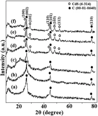
Figure 2shows the X-ray diffraction patterns of the pristine- MWCNT (a), oxidized-MWCNT (b), MWCNT-MA-Octene1 (c), MWCNT–MA–1-octene/CdS(2 h) (d), MWCNT–MA –1-octene/CdS(4 h) (e) and MWCNT–MA –1-octene/CdS (6 h) (f) samples. The peaks at 26.34, 44.82and 77.58can be assigned to reflections from the (002), (101) and (110) crystal- lographic planes of multiwall carbon nanotubes, respectively (PDF no.: 00-001-0640). The interplanar d spacing for these planes was calculated as 0.338(3), 0.202(21) and 0.123(05) respectively which is in good agreement with the standart d spacings (0.338, 0.202 and 0.123) of carbon in PDF no.: 00- 001-0640 powder diffractionfile. These peaks are observable in
the patterns of the other samples as well. However, slight differ- ences in peak widths and intensities indicate that the oxidation and functionalization processes have affected the ordering of the graphitic layers to some extent. Peaks at 24.70, 26.48, 28.02, 43.54, 47.78and 51.78inFigure 2d-fcan be assigned to the (100), (002), (101), (110), (103) and (112) reflections of hexagonal CdS (JPDS no.: 6–314).
The average coherence length (Lc) or mean crystallite size along the c-axis (the crystallographic c-axis is the one perpen- dicular to the long axis of the MWCNTs) was estimated with Scherrer’s formula using (002) Bragg peak[49]:
LhklDð0:9£λÞ6 ðb£cosuÞ
whereλis the X-ray wavelength,uis the scattering angle andb is the peak full width at half maximum in radians. The values for Lcgive the average stacking height of graphitic planes in the MWCNT walls. The results were 10.5 nm (MWCNT), 6.2 nm (oxidized-MWCNT) and 8.3 nm (MWCNT–MA–1-octene).
It can be seen from the results that the value of Lc decreases from pristine MWCNT to oxidized MWCNT. The reason behind this is that oxidation by KMnO4 results in the partial loss of the outermost graphitic layers and the introduction of defects, which reduce the symmetry of the plane. Binding the MA–1-octene copolymer to the defected regions increases the Lc value. This happens because the polymer layers cover the surface of the MWCNTs and restore the smoothness and orderliness on the surface to some extent by securing exfoliated wall parts back to their previous positions. The formation of the CdS nanocrystals reduces the order and therefore, the Lc
value decreases again. The mean diameters of CdS nanopar- ticles obtained with 2 hours, 4 hours and 6 hours of cavitation
Figure 1.FTIR spectra for pristine-MWCNT (a), oxidized-MWCNT (b), MWCNT–MA –1-octene (c), MWCNT–MA–1-octene/CdS(2 h) (d), MWCNT–MA–1-octene/
CdS(4 h) (e) and MWCNT–MA–1-octene/CdS(6 h) (f) samples. Figure 2.XRD patterns of the pristine-MWCNT (a), oxidized-MWCNT (b), MWCNT– MA–1-octene (c), MWCNT–MA –1-octene/CdS(2 h) (d), MWCNT–MA–1- octene/CdS(4 h) (e) and MWCNT–MA–1-octene/CdS(6 h) (f) samples.
were calculated with Scherrer’s formula using (100) and (101) peaks and the results were as 7.9 nm, 4.2 nm and 3.9 nm, respectively. The sonication time affects the size of the obtained CdS nanoparticles. Thus, with increasing of the time period we can easily reduce the size of the nanoparticles to some extent.
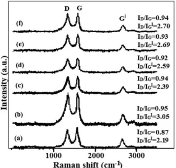
Raman spectra of pristine MWCNT (a), oxidized-MWCNT (b), MWCNT–MA–1-octene (c) MWCNT–MA–1-octene/
CdS(2 h) (d), MWCNT – MA – 1-octene/CdS(4 h) (e) and MWCNT–MA –1-octene/CdS(6 h) (f) samples are depicted inFigure 3. The Raman spectrum of MWCNTs features three major peaks: the D band, G band and G’band.[50]The D band is a disorder induced peak at »1342 cm¡1 corresponding to phonon scattering from sp3defects in the nanotubes as well as in amorphous carbon. The G band (»1574 cm¡1) is the result of the ordered high-frequency in-plane stretching of the C-C bonds. The G’band (»2684 cm¡1) is the result of a double res- onance process. This band does not require an elastic defect- related scattering process and is observable for defect-free sp2 carbons as well. The ratio between the intensities of D and G bands (ID/IG) is proportional to the extent of defect concentra- tion. Therefore, it can be used to quantify the extent of oxida- tion and functionalization. ID/IGratios for pristine MWCNT, oxidized MWCNT, MWCNT – MA – 1-octene, MWCNT – MA – 1-octene /CdS(2 h), MWCNT – MA –1-octene /CdS (4 h) and MWCNT–MA–1-octene /CdS(6 h) are 0.87, 0.95, 0.94, 0.92, 0.93 and 0.94 respectively. These values suggest that while oxidation has increased the number of sidewall defects in the MWCNTs to some extent, the subsequent grafting and CdS deposition steps did not alter the sp3/sp2 carbon ratio of the oxidized nanotube wall structure any further.
Figure 4shows the TEM images of pristine MWCNT (a), oxi- dized-MWCNT (b), MWCNT–MA–1-octene (c), MWCNT– MA–1-octene /CdS(2 h) (d), MWCNT–MA–1-octene /CdS (4 h) (e) and MWCNT–MA–1-octene /CdS(6 h) (f) samples. It can be seen from theFigure 4athat, the average diameter of the pristine nanotubes is 16.5§2.5 nm. After the purification and
oxidation processes (Figure 4b) the exfoliation of the outer layers of the MWCNTs changes the apparent diameter of the tubes to 19.8§1.7 nm.Figure 4coffers a view of the grafted polymer as shadows covering the intertubular space and the same phenome- non is also visible inFigure 4d-f. The average thickness of the copolymer cover layer is 22.3§2.9 nm. Moreover, inFigure 4d CdS nanocrystals of 8.17§0.3 nm average diameter can be seen embedded in the polymer cover. These nanocrystals feature a very narrow size distribution and they are uniformly dispersed in the polymer layer. This uniformity confirms that the CdS nanocrystals are mostly formed at the functionalities offered by the polymer macromolecules, whereas the functional groups of the carbon nanotubes play only a minor (if any) role in the nanocrystal synthe- sis. The embedded CdS nanoparticles with a narrow size distribu- tion can also be observed in the TEM images for the other nanocomposites (Figure 4e,f). As it can be seen from the images, the average diameters of CdS nanoparticles in the MWCNT–MA –1-octene /CdS(2 h), MWCNT–MA–1-octene /CdS(4 h) and MWCNT–MA–1-octene /CdS(6 h) nanocomposites are 8.17§ 0.3 nm, 4.93 § 0.4 nm and 4.17 § 0.3 nm, respectively. The decrease in average diameters is the result of the sonication process.
With increasing of the sonication time we achieve rather smaller nanoparticles.
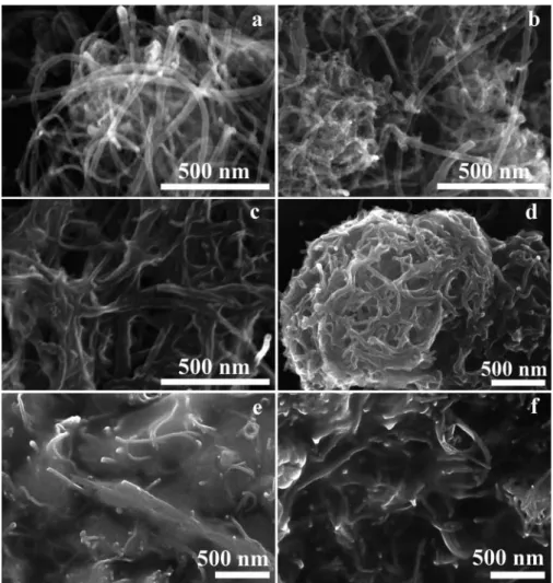
Characteristic SEM micrographs of pristine MWCNT (a), oxidized-MWCNT (b), MWCNT – MA – 1-octene (c), MWCNT–MA–1-octene /CdS(2 h) (d), MWCNT–MA–1-
Figure 3.Raman spectra of the pristine MWCNT (a), oxidized-MWCNT (b), MWCNT –MA–1-octene (c), MWCNT–MA–1-octene /CdS(2 h) (d), MWCNT–MA–1- octene/CdS(4 h) (e) and MWCNT–MA–1-octene/CdS(6 h) (f) samples.
Figure 4.TEM images of the pristine MWCNT (a), oxidized-MWCNT (b), MWCNT– MA–1-octene (c), MWCNT–MA–1-octene /CdS(2 h) (d), MWCNT–MA–1- octene /CdS(4 h) (e) and MWCNT–MA–1-octene /CdS(6 h) (f) samples.
258 E. Y. MALIKOV ET AL.
octene /CdS(4 h) (e) and MWCNT–MA–1-octene /CdS(6 h) (f) samples are depicted inFigure 5. The unmodified, smooth surface of pristine MWCNTs visible inFigure 5a confirms the TEM-derived diameter estimation. In contrast, the surface of the oxidized MWCNTs looks rough because of the defected regions created by oxidation (Figure 5b). The polymer coating of the tubes can be observed inFigures 5c-f. The MA–1-octene copolymer macromolecules were attached to the defect-acti- vated regions of the MWCNTs by the“grafting from”method
and cover the whole nanotube surface. This surface polymer layer prevents MWCNT entanglement and makes the material soluble in hydrophilic solvents. The CdS-containing nanocom- posites exhibit the same morphologies as the polymer-grafted nanotubes. SEM imaging does not allow the direct observation of the CdS nanoparticles inFigure 5d-feven though their pres- ence was confirmed by TEM (Figure 4d-f).
The optical properties and the band gap of the synthesized materials were characterized by UV-vis spectroscopy.Figure 6
Figure 5.SEM images of the pristine MWCNT (a), oxidized-MWCNT (b), MWCNT–MA–1-octene (c), MWCNT–MA–1-octene /CdS(2 h) (d), MWCNT–MA–1-octene /CdS(4 h) (e) and MWCNT–MA–1-octene /CdS(6 h) (f) samples.
Figure 6.UV-vis absorbance spectra (A) and dependence of [F(R)hn]1/2on hn(B) for pristine MWCNT (1), oxidized MWCNT (2), MWCNT–MA–1-octene/CdS(2 h) (3), MWCNT–MA–1-octene/CdS(4 h) (4) and MWCNT–MA–1-octene/CdS(6 h) (5) samples.
shows the absorbance spectra (A) and dependence of [F(R) hn]1/2on hn(B) for pristine MWCNT (1), oxidized MWCNT (2), MWCNT–MA–1-octene/CdS(2 h) (3), MWCNT–MA –1-octene/CdS(4 h) (4) and MWCNT–MA–1-octene/CdS (6 h) (5) samples. The absorbance intensities of the samples uniformly decrease with increasing of the wavelength. The peak observed at the 273 nm in the absorbance spectrum of the oxidized MWCNT in the result of the plasmonic effect.[51,52]
The Kubelka-Munk approach is applied in order to charac- terize the optical properties using the result from optical reflec- tance. The Kubelka-Munk equation is expressed as follows[53]:
F Rð ÞDð1¡RÞ26 2RDk6 s
where R is the absolute reflectance, k is the molar absorption coefficient and s is the scattering coefficient. The band gap energies (Eg) of the samples can be calculated with plotting the dependence of [F(R)hn]1/2 on hnand extrapolating the linear parts of the curves to the abscissa energy axis.
UV-vis spectra were recorded in the 190–1100 nm range and the band gap for MWCNT – MA – 1-octene/CdS(2 h), MWCNT–MA–1-octene/CdS(4 h) and MWCNT–MA–1- octene/CdS(6 h) samples obtained from the dependence of the [F(R)hn]1/2 on hnwere 3.94 eV, 4.1 eV and 4.35 eV, respec- tively. These results are higher than that of bulk CdS (2.42 eV) and show the blue shifting due to the crystalline size.[54,55]
These rather broad band gap values suggest that the nanocom- posites couldfind applications in optical devices such as optical insulators and optical harvesting parts of photovoltaic devices.
The average diameters of the CdS nanocrystals in MWCNT –MA –1-octene/CdS(2 h), MWCNT – MA –1-octene/CdS (4 h) and MWCNT–MA–1-octene/CdS(6 h) nanocomposites were calculated as 6.2 nm, 5.9 nm and 5.5 nm respectively.
These results show that the sonication time affects the size of the obtained CdS nanoparticles. Thus, with increasing of the sonication time we can easily reduce the size of the nanopar- ticles. These results correspond with the results obtained from the other methods.
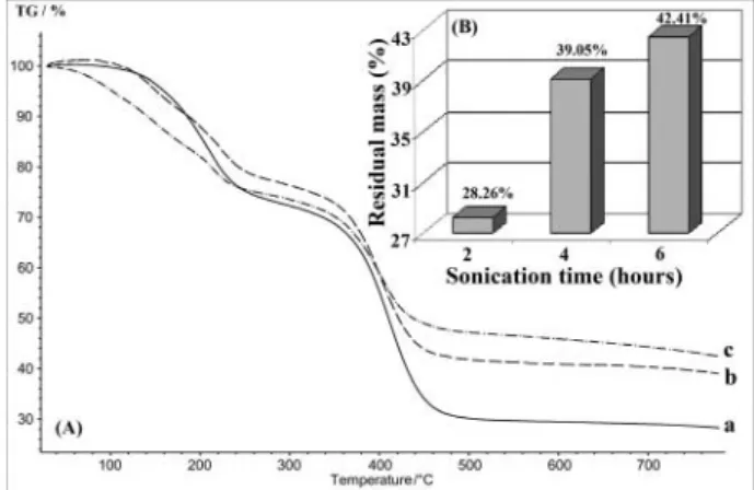
Figure 7shows the TG curves (A) and dependence of residual mass on the sonication time (B) for MWCNT–MA–1-octene/
CdS(2 h) (a), MWCNT – MA – 1-octene/CdS(4 h) (b) and MWCNT–MA –1-octene/CdS(6 h) (c) samples. The residual masses for MWCNT– MA –1-octene/CdS(2 h), MWCNT –
MA –1-octene/CdS(4 h) and MWCNT–MA–1-octene/CdS (6 h) samples defined from the TG curves were 28.26%, 39.05%
and 42.41%, respectively. It is clear that the residual mass increases with increasing of the sonication time. The reason is that, the amount of the CdS nanoparticles increases with the increasing of the sonication time. Since the increasing of the son- ication time reduces the size of nanoparticles, the spatial hin- drances in formation of excess amount of nanoparticles are removed. Thus, the high amount of the lower size nanoparticles is formed during the process. Moreover, the macromolecules of the copolymer grafted to the surface of the MWCNTs are destroyed with increasing of the sonication time and the polymer content in the MWCNT–MA–1-octene/CdS nanocomposite decreases which results in high residual mass. There are 2–3 clear mass losses in the TG curves of the samples which are the result of desorption of atmospheric components and degradation of the grafted copolymer macromolecules in the nanocomposite.
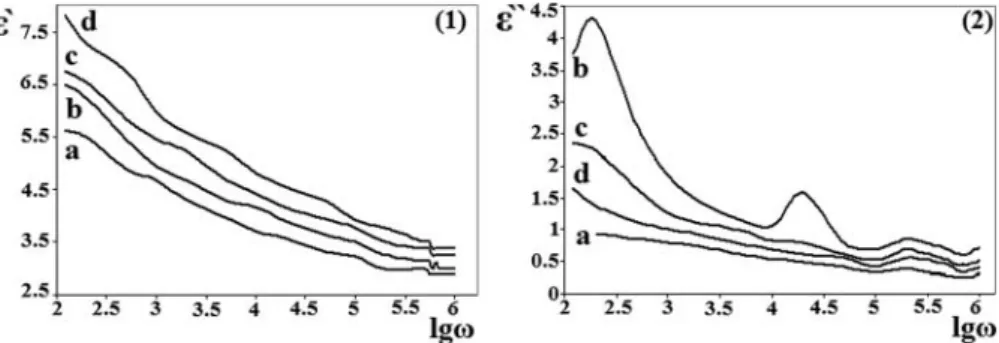
The electrical properties of the obtained nanocomposites were investigated by Immittance meter MNIPI E7-20 device under alternating electric field, in 200 Hz-1 MHz frequency diapason. The specimens were prepared by mixing of MWCNT based nanocomposites with the aqueous polyvinyl alcohol solu- tion and formation of thinfilms of this mixture at room tem- peratures. The specimens were placed between two electrodes in “sandwich”manner. The both sides of the thin films were provided by adhesive copper tape contact materials to ensure proper contact between electrodes and thin film. The thick- nesses of the thin films were defined by the mechanical micrometer. The electrical capacitances and resistances of the specimens were measured under different frequencies. The fol- lowing equations were used to characterize the real and imagi- nary parts of permittivity[56]:
e0DCd6 eS e00Dd6 ReSv
where,e’is the real part of the permittivity,e”is the imaginary part of the permittivity,e0is the dielectric constant in vacuum (8.854£10¡12F/m), d is the thickness of the thinfilm, S is the area of the electrodes, C is the parallel plate capacitance, R is resistance,vis frequency.
Figure 8andFigure 9show that the embedded semiconduc- tor nanoparticles within the polymer matrix change the electri- cal properties of the system. The reason is the change of the concentration of polymer macromolecules in the polymer
Figure 7.TG curves (A) and dependence of residual mass on the sonication time (B) for MWCNT–MA–1-octene/CdS(2 h) (a), MWCNT–MA–1-octene/CdS(4 h) (b) and MWCNT–MA–1-octene/CdS(6 h) (c) samples.
Figure 8.Dependence of resistance of the pristine-PVA (a), PVA/MWCNT–MA–1- octene/CdS(2h) (b), PVA/MWCNT–MA–1-octene/CdS(4h) (c) and PVA/MWCNT– MA–1-octene/CdS(6h) (d) samples on the logarithmic frequency.
260 E. Y. MALIKOV ET AL.
nanocomposite system due to the insertion of the nanoparticles into the polymer matrix. Moreover, since the nanocomposites are the two-phase systems, an interaction between nanopar- ticles and polymer matrix can increase the polarization of the system under the external electricalfield and that can increase the dielectrical permittivity.
It was defined that, in all investigated specimens the electri- cal capacitances and resistances are inversely proportional to frequency. Thus, the electrical conductivity increases with increasing of the frequency. Since, the addition of the obtained nanostructures to the non-conductive polymer makes them conductive or semiconductive nanocomposites, the obtained nanostructures can be used as the additives for preparation of various conductive or semiconductive nanocomposites.
4. Conclusion
Different periods of time for sonication were applied in order to synthesize CdS nanoparticles within the matrix obtained by the functionalization of the multiwall carbon nanotubes with maleic anhydride – 1-octene copolymer through “grafting from”
approach. The used MWCNTs were synthesized by CCVD from acetylene over an Fe,Co/Al2O3catalyst and oxidized in KMnO4
solution to create oxygen-containing surface functional groups and defected regions on the nanotube walls to make them avail- able for grafting with polymer. The synthesized nanocomposites were characterized by FTIR, Raman and UV-vis spectroscopy as well as by XRD, TEM, SEM and TG. The results confirmed the success of the functionalization and grafting reactions and revealed a highly uniform CdS nanoparticle distribution both in terms of particle diameter and in spatial distribution within the polymer coating. Futhermore, the effect of the sonication time on the efficiency of the synthesis process, size distribution and properties of the CdS nanoparticles was defined. Also the electri- cal properties of the obtained nanocomposites were investigated.
It was revealed that, the obtained nanocomposites feature a band gap well in the UV region even when CdS nanoparticles are present. Potential applications for these nanocomposite materials are likely to be found in the optical device industry or in the manufacturing of smart semiconductors.
Funding
This work was supported by the EC FP7 program (NAPEP Grant agree- ment number: 266600). The financial support from the Hungarian
GINOP-2.3.2-15-2016-00013 “Intelligent materials based on functional surfaces¡from syntheses to applications” project as well as from the NKFIH (OTKA) K120115 (Z.K.) and K126065 (A.K.) projects is acknowledged.
References
[1] Kamat, P. V. Quantum Dot Solar Cells. Semiconductor Nanocrystals as Light Harvesters.J. Phys. Chem. C2008,112, 18737–18753.
[2] Guijarro, N.; Lana-Villarreal, T.; Mora-Sero’, I.; Bisquert, J.; Gomez, R. CdSe Quantum Dot-Sensitized TiO2Electrodes: Effect of Quan- tum Dot Coverage and Mode of Attachment.J. Phys. Chem. C2009, 113(10), 4208–4214.
[3] Yue, Y.; Ge, M. Y.; Liu, Y.; Wu, J.; Chem, P.; Lin, L.; Liu, Y. F.; Sun, Y.; Chen, X.; Dai, N. Highly Stable CdSe/CdS/ZnS Fluorophores in Acidic Environment: Acile Preparation and Modification of Core/
shell/shell Nanocrystals. Chem. Res. Chin Universities2010,26(6), 871–875.
[4] Akperov, O. H.; Muradov, M. B.; Malikov, E. Y.; Akperov, E. O.;
Mammadova, R. E.; Eyvazova, G. M.; Kukovecz,A.; K onya, Z. Syn- thesis and Characterization of CdS Nanocrystals in Maleic Anhy- dride–Octene-1–Vinylbutyl Ether Terpolymer Matrix. Physica E 2016,81, 150–155.
[5] Ibrahim, A. A. Electrical proPerties of the CdS/InP Solar Cell for Photovoltaic Applications.J. Mater. Sci.: Mater. Electron.2010,21 (5), 491–495.
[6] Barrelet, C. J.; Wu, Y.; Bell, D. C.; Lieber, C. M. Synthesis of CdS and ZnS Nanowires Using Single-Source Molecular Precursors. J. Am.
Chem. Soc.2003,125(38), 11498–11499.
[7] Schlamp, M. C.; Peng, X. G.; Alivisatos, A. P. IMPROVED Efficiencies in light Emitting Diodes made with CdSe(CdS) core/shell type Nanocrystals and a Semiconducting Polymer.J. Appl. Phys.1997,82, 5837–5842.
[8] Yu, H. G.; Huang, X.; Wang, P.; Yu, J. G. Enhanced Photoinduced- Stability and Photocatalytic Activity of CdS by Dual Amorphous Cocatalysts: Synergistic Effect of Ti(IV)-Hole Cocatalyst and Ni(II)- Electron Cocatalyst.J. Phys. Chem. C2016,120(7), 3722–3730.
[9] Barrelet, C. J.; Greytak, A. B.; Lieber, C. M. Nanowire Photonic Cir- cuit Elements.Nano Lett.2004,4(10), 1981–1985.
[10] Yu, C. L.; Zhou, W. Q.; Yu, J. M.; Yang, J. G.; Fan, Q. Z. Rapid Fabri- cation of CdS Nanocrystals with well Mesoporous Structure under Ultrasound Irradiation at Room Temperature. Chem. Res. Chin.
Univ.2012,28(1), 124–128.
[11] Stanic, V.; Etsell, T. H.; Pierre, A. C.; Mikula, R. J. Sol-Gel Processing of ZnS.Mater. Lett.1997,31(1–2), 35–38.
[12] Chen, J.; Wang, X.; Zhang, Z. In Situ Fabrication of Mesoporous CdS Nanoparticles in Microemulsion by Gamma Ray Irradiation.Mater.
Lett.2008,62(4–5), 787–790.
[13] Liang, Y.; Zhen, C.; Zou, D.; Xu, D. Preparation of Free-Standing Nanowire Arrays on Conductive Substrates.J. Am. Chem. Soc.2004, 126(50), 16338–16339.
[14] Sun, S. Q.; Li, T. Synthesis and Characterization of CdS Nanopar- ticles and Nanorods via Solvo-Hydrothermal Route.Cryst. Growth Des.2007,7(11), 2367–2371.
Figure 9.Dependences of the real part (1) and the imaginary part (2) of permittivity of the pristine-PVA (a), PVA/MWCNT–MA–1-octene/CdS(2h) (b), PVA/MWCNT–MA –1-octene/CdS(4h) (c) and PVA/MWCNT–MA–1-octene/CdS(6h) (d) samples on the logarithmic frequency.
[15] Yu, S. H.; Qian, Y. T.; Shu, L.; Xie, Y.; Yang, L.; Wang, C. S. Solvent Thermal Synthesis and Characterization of Ultrafine Powder of Bis- muth Sulfide.Mater. Lett.1998,35(1–2), 116–119.
[16] Gautam, U. K.; Seshadri, R.; Rao, C. N. R. A Solvothermal Route to CdS Nanocrystals.Chem. Phys. Lett.2003,375(5–6), 560–564.
[17] Ethayaraja, M.; Dutta, K.; Muthukumaran, D.; Bandyopadhyaya, R.
Nanoparticle Formation in Water-in-Oil Microemulsions: Experi- ments, Mechanism, and Monte Carlo Simulation.Langmuir2007,23 (6), 3418–3423.
[18] Kundu, S.; Lee, H.; Liang, H. Synthesis and Application of DNA¡CdS Nanowires within a Minute using Microwave Irradia- tion.Inorg. Chem.2009,48(1), 121–128.
[19] Shen, G. Z.; Cho, J. H.; Yoo, J. K.; Yi, G. C.; Lee, C. J. Synthesis of Sin- gle-Crystal CdS Microbelts using a Modified Thermal Evaporation method and their Photoluminescence.J. Phys. Chem. B 2005,109 (19), 9294–9298.
[20] Thiruvengadathan, R.; Levi-Kalisman, Y.; Regev, O. Synergetic Effect of Ultrasound and Sodium Dodecyl Sulphate in the Formation of CdS Nanostructures in Aqueous Solution.Ultrason. Sonochem.2007, 14(3), 398–404.
[21] Wingkei, H. O.; Yu, J. C. Sonochemical Synthesis and Visible light Photocatalytic Behavior of CdSe and CdSe/TiO2 Nanoparticles. J.
Mol. Catal. A: Chem.2006,247(1–2), 268–274.
[22] Tiehm, A.; Krabnitzer, S.; Koltypin, Y.; Gedanken, A. Chloroethene Dehalogenation with Ultrasonically Produced Air-Stable Nano Iron.
Ultrason. Sonochem.2009,16(5), 617–621.
[23] Vijayakumar, R.; Koltypin, Y.; Felner, I.; Gedanken, A. Sonochemical Synthesis and Characterization of Pure Nanometer-Sized Fe3O4Par- ticles.Mater. Sci. Eng. A2000,286(1), 101–105.
[24] Bang, J. H.; Suh, W. H.; Suslick, K. S. Quantum Dots from Chemical Aerosolflow Synthesis: Preparation, Characterization, and Cellular Imaging.Chem. Mater.2008,20(12), 4033–4038.
[25] Flannigan, D. J.; Suslick, K. S. Plasma Formation and Temperature Measurement during Single-Bubble Cavitation.Nat2005,434, 52– 55.
[26] Suslick, K. S.; Price, G. J. Applications of Ultrasound to Materials Chemistry.Annu. Rev. Mater. Sci.1999,29, 295–326.
[27] Mdleleni, M. M.; Hyeon, T.; Suslick, K. S. Sonochemical Synthesis of Nanostructured Molybdenum Sulfide.J. Am. Chem. Soc.1998,120, 6189–6190.
[28] Suslick, K. S.; Doktycz, S. J. The Effects of Ultrasound on solids. In Advances in Sonochemistry, Mason, T. J. Ed.; JAI Press: New York, 1990; Vol. 1, pp. 197–230.
[29] Avivi (Levi), S.; Palchik, O.; Palchik, V.; Slifkin, M. A.; Weiss, A. M.;
Gedanken, A. Sonochemical Synthesis of Nanophase Indium Sulfide.
Chem. Mater.2001,13(6), 2195–2200.
[30] Guo, W.; Lin, Z.; Wang, X.; Song, G. Sonochemical Synthesis of Nanocrystalline TiO2by Hydrolysis of Titanium Alkoxides.Micro- electron. Eng.2003,66(1–4), 95–101.
[31] Malikov, E. Y.; Muradov, M. B.; Akperov, O. H.; Eyvazova, G. M.;
Puskas, R.; Madarasz, D.; Nagy, L.; Kukovecz,A.; K onya, Z. Synthesis and Characterization of Polyvinyl Alcohol based Multiwalled Carbon Nanotube Nanocomposites.Physica E2014,61, 129–134.
[32] Altay, M. C.; Malikov, E. Y.; Eyvazova, G. M.; Muradov, M. B.;
Akperov, O. H.; Puskas, R.; Madarasz, D.; Konya, Z.; Kukovecz,A.
Facile Synthesis of Cus Nanoparticles Deposited on Polymer Nano- composite foam and Their Effects on Microstructural and Optical Properties.Eur. Polym. J.2015,68, 47–56.
[33] Malikov, E. Y.; Altay, M. C.; Muradov, M. B.; Akperov, O. H.;
Eyvazova, G. M.; Puskas, R.; Madarasz, D.; Kukovecz,A.; K onya, Z.
Synthesis and Characterization of Cds Nanoparticle Based Multiwall Carbon Nanotube–Maleic Anhydride–1-Octene Nanocomposites.
Physica E2015,69, 212–218.
[34] Wang, Z. W.; Shirley, M. D.; Meikle, S. T.; Whitby, R. L. D.;
Michalovsky, S. V. The Surface Acidity of Acid Oxidised Multi- Walled Carbon Nanotubes and the Influence of in-Situ Generated Fulvic Acids on Their Stability in Aqueous Dispersions. Carbon 2009,47(1), 73–79.
[35] Altay, M. C.; Eroglu, S. Synthesis of Multi-Walled C Nanotubes by Fe–Ni (70 wt.%) Catalyzed Chemical Vapor Deposition From Pre- Heated CH4.Mater. Lett.2012,67(1), 124–127.
[36] Paradise, M.; Goswami, T. Carbon Nanotubes – Production and Industrial Applications.Mater. Des.2007,28, 1477–1489.
[37] Gulas, M.; Cojocaru, C. S.; Fleaca, C. T.; Farhat, S.; Veis, P.;
Normand, F. L. Synthesis of Carbon Nanbotubes by Plasma- Enhanced Cvd Process: Gas Phase Study of Synthesis Conditions.
Eur. Phys. J. Appl. Phys.2008,43, 353–356.
[38] Scott, C. D.; Arepalli, S.; Nikolaev, P.; Smalley, R. E. Growth Mecha- nisms for Single-Wall Carbon Nanotubes in a Laser Ablation Pro- cess.Appl. Phys. A2002,74(11), 573–580.
[39] Rafique, M. M. A.; Iqbal, J. Production of Carbon Nanotubes by Dif- ferent Routes—; A Review. J. Encapsulation Adsorpt. Sci. 2011, 1, 29–34.
[40] Thostenson, E. T.; Ren, Z. F.; Chou, T.-W. Advances in the Science and Technology of Carbon Nanotubes and their Composites: A Review.Compos. Sci. Technol.2001,61(13), 1899–1912.
[41] Hosseini, A. A.; Allahyari, M.; Besheli, S. D. Synthesis of Carbon Nanotubes, Nano Fibers and Nano Union by Electric Arc Discharge Method Using Nacl accuse as Solution and Fe and Ni Particles and Catalysts.Int. J. Sci. Environ. Tech.2012,1(3), 217–229.
[42] Sahoo, N. G.; Rana, S.; Cho, J. W.; Li, L.; Chan, S. H. Polymer Nano- composites Based on Functionalized Carbon Nanotubes. Prog.
Polym. Sci.2010,35(7), 837–867.
[43] Malikov, E. Y.; Akperov, O. H.; Muradov, M. B.; Eyvazova, G. M.;
Kukovecz,A.; K onya, Z. Fuller.Nanotub. Car. N.2017,25(9), 540– 544.
[44] Rike, Y.; Holia Sudirman, O.; Yukie, S.; Tadahisa, I.; Jun-ichi, A.
Analysis of Functional Group Sited on Multi-Wall Carbon Nanotube Surface.Open Mater. Sci. J.2011,5, 242–247.
[45] Vesali Naseh, M.; Khodadadi, A. A.; Mortazavi, Y.; Alizadeh Sahraei, O.; Pourfayaz, F.; Mosadegh Sedghi, S. Functionalization of carbon nanotubes using nitric acid oxidation and DBD plasma.Int. J. Chem.
Biol. Eng.2009,2(2), 66–68.
[46] Abuilaiwi, F. A.; Laoui, T.; Al-Harthi, M.; Atieh, M. A. Modification and Functionalization of Multiwalled Carbon Nanotube (MWCNT) via Fischer Esterification.Arab. J. Sci. Eng.2010,35(1C), 37–48.
[47] Barra, G. M. O.; Crespo, J. S.; Bertolino, J. R.; Soldi, V.; Pires, A. T. N.
Maleic Anhydride Grafting on EPDM: Qualitative and Quantitative Determination.J. Braz. Chem. Soc.1999,10(1), 31–34.
[48] Barman, J.; Borah, J. P.; Sarma, K. C. Synthesis and Characterization of CdS Nanoparticles by Chemical Growth Technique.Optoelectron.
Adv. Mat.2008,2(12), 770–774.
[49] Maurin, G.; Stepanek, I.; Bernier, P.; Colomer, J. F.; Nagy, J. B.; Henn, F. Segmented and Opened Multi-Walled Carbon Nanotubes.Carbon 2001,39, 1273–1278.
[50] Dresselhaus, M. S.; Ado, J.; Hofman, M.; Dresselhaus, G.; Saito, R.
Perspectives on Carbon Nanotubes and Graphene Raman Spectros- copy.Nano. Lett.2010,10(3), 751–758.
[51] Swain, S. K.; Pradhan, A. K.; Sahu, H. S. Synthesis of Gas Barrier Starch by Dispersion of Functionalized Multiwalled Carbon Nano- tubes.Carbohyd. Polym.2013,94(1), 663–668.
[52] Giuliani, A.; Placidi, M.; Di Francesco, F.; Pucci, A. A New Polysty- rene-Based Ionomer/MWCNT Nanocomposite for Wearable skin Temperature Sensors.React. Funct. Polym.2014,76, 57–62.
[53] Kamil, A. M.; Hussein, F. H.; Halbus, A. F.; Bahnemann, D. W. Prep- aration, Characterization and Photocatalytic Applications of MWCNTs/TiO2Composite.Int. J. Photoenergy2014,2014, 1–8.
[54] Kalandaragh, Y. A.; Muradov, M. B.; Mamedov, R. K.; Behboudnia, M.; Khodayari, A. Structural, Compositional and Optical Characteri- zation of Water Soluble CdS Nanoparticles Synthesized by Ultrasonic Irradiation.Optoelectron. Adv. Mat.2008,2(1), 42–45.
[55] Manickathai, K.; Viswanathan, S. K.; Alagar, M. Synthesis and Char- acterization of CdO and CdS Nanoparticles.Indian J. Pure Ap. Phys.
2008,46, 561–564.
[56] Simonyi, K. Theoretische Elektrotechnik, Barth Verlagsgessellschaft:
Deutschland,1993, 973 p. ISBN: 3335003756.
262 E. Y. MALIKOV ET AL.