CHAPTER Κ )
Microdetermination of Unsaturation (Double Bonds)—Hydrogen Number
The determination of the amount of unsaturation (double bonds) in an organic compound is accomplished by catalytic hydrogénation carried out at approxi
mately atmospheric pressure using platinic or palladous oxide as the catalyst.
The results may be expressed in various ways, e.g., mois of hydrogen consumed per 100 grams of sample, grams of hydrogen consumed per 100 grams of sample or grams of sample reacting with one mol of hydrogen (hydrogen number).
The theoretical hydrogen number is equal to the molecular weight divided by the number of double bonds per molecule (compare Chapter 1 5 ) . The reaction may be represented by the following:
\ / \ /
C = C * C H C H
/ \ H2 / \
This procedure, obviously, is applicable only to those compounds which can be hydrogenated at atmospheric pressure and, therefore, the reader is strongly advised to refer to the literature
2 , 1 2on the subject of hydrogénation before attempting a determination on a specific compound.
Quantitative hydrogénation as a means of determining the amount of unsaturation has advantages over the halogenation methods (addition of bromine or iodine to the double bond) which are seldom used because of errors.
3 2It is not subject to the errors resulting from the presence of two or more con
jugated double bonds or from complex molecular structure.
3 2The high ratio of catalyst to sample aids in obtaining complete hydrogénation and in over
coming the effects of poisoning of the catalyst by small amounts of impurities in the sample being analyzed.
Reagents
GLACIAL ACETIC ACID
Reagent grade of glacial acetic acid is used as the solvent, of course, provided that the sample is soluble in it. Otherwise, some other suitable pure solvent must be used, such as ethanol, methanol, etc. With glacial acetic acid, there is less fire hazard than with ethanol and of the above-mentioned three, methanol presents the greatest hazard.
4 9 5
19. Unsaturation (Double Bonds) 496
CATALYSTS
Platinic oxide,
1-
9palladous oxide,
4 7or palladium on carbon ( 1 0 % ) ,
3 2may be used as the catalyst depending upon the nature of the sample. The author strongly advises these being purchased, since they are commercially available,*
in preference to being prepared by the analyst. At all times, the catalyst should be handled with care due to the fire hazard.
Apparatus
Note: Wherever interchangeable ground joints are not used, connections should be made with plastic tubing—not rubber.
HYDROGEN CYLINDER AND REDUCING VALVE
Prepurified hydrogen is required.
NITROGEN CYLINDER AND REDUCING VALVE
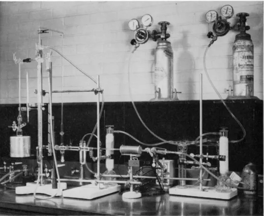
Prepurified nitrogen is desirable, but not necessary. It is good practice to sweep the apparatus with nitrogen, following the determination, before opening the reaction flask containing catalyst and solvent to the air to reduce fire hazard (see photograph of author's setup, Fig. 1 9 8 ) .
FRIEDRICH BOTTLES51
These are used as pressure regulators (see Fig. 1 9 8 ) . They are the same as described in Chapter 14 (see Fig. 1 7 4 ) . The overflow tubes should be vented to an exhaust hood or to the outdoors.
SCRUBBING TOWERS
Scrubbing towers filled with both Ascarite
5 1and Anhydrone
5 1are used in the purification train (see Fig. 1 9 8 ) .
PREHEATER TYPE MICROCOMBUSTION FURNACE-1
A preheater type of microcombustion furnace (see Fig. 173, Chapter 1 4 ) is used in the purification train (see Figs. 198 and 1 9 9 ) .
PURIFICATION TUBE
A section of combustion tube with ground joints attached and containing either platinized asbestos (Chapter 9 ) or platinum contact stars (Fig. 152, Chapter 1 0 ) heated to 650° C. in the preheater type of microcombustion furnace is used as part of the purification train.
* American Platinum Works, Newark, New Jersey.
497 Apparatus
BUBBLE COUNTER-U-TUBE
This is identical with that used for the carbon-hydrogen determination (Chap
ter 9, Fig. 1 2 0 ) . It should, however, have interchangeable ground joints at
tached to both side arms as shown in Fig. 199. The filling (Ascarite, An
hydrone, sulfuric acid) is identical to that described in Chapter 9.
HYDROGENATION APPARATUS*251
The apparatus used is shown in Figs. 198 and 199. The purification train is attached to a tube, F, for saturating the hydrogen with the solvent, the gas
FIG. 198. Microhydrogenation apparatus. Photograph showing units of purification train and attachment of nitrogen source for sweeping purposes to reduce fire hazard.
passing through a sintered glass plate immersed to a depth of about 2.5 cm.
in the solvent. This tube is connected by means of an interchangeable ground
joint to the burette-manometer combination, at the top of which are two three-
way stopcocks, one above the other, 1 and 2, respectively. All connections, other
than by means of interchangeable ground joints are affected by means of
plastic tubing. The burette, G, and the manometer, H, have parallel and co-
499 Procedure
inciding graduations, with 0.02-ml. intervals from 0 to 7 ml. The mercury in the burette, G, and the manometer, H, is leveled by raising or lowering the leveling bulb, 1, attached to a rack and pinion device, as shown in Fig. 198 (also compare Fig. 202, Chapter 2 0 ) . The reaction unit (flask and connecting tube-stopcock) and burette, G, are connected by means of ball and socket joint ( g> 1 2 / 2 ) , ] , held by a suitable clamp. The reaction flask ( 2 0 ml. capacity), K, and connecting tube-stopcock, 3, are connected by means of an interchange
able ground joint ( f 1 4 / 2 0 ) , L. The side arm and stopper, M, are prepared from members of an interchangeable ground joint (!* 1 0 / 1 2 ) . The stopper, which extends into the neck of the flask, has a groove near the tip and per
pendicular to its long axis. [As an optional attachment, the flask may be equipped with a No. 2 stopcock attached to the neck (Fig. 1 9 9 ) , so that tubing may be connected to carry off hydrogen used during the sweep out period]. The sample cup, N, is hung on the stopper, M, and is dropped to the bottom of the flask by turning the stopper. The sample cup is prepared from aluminum rod and is 8 mm. in length and 6 mm. in diameter with a volume of approximately 0.1 ml. A nichrome handle is attached to the cup through two holes drilled on opposite sides. A glass covered magnetic stirring bar, O, is used in the reaction flask. The cup attached to the stopcock, 3, facilitates cleaning the tube leading to the reaction flask. All ground joints should be thoroughly greased with Sisco No. 300 stopcock grease (see Chap
ter 7 ) .
[Note: I f nitrogen is used for sweeping purposes at the end of the de
termination, the stopcock, 1, is attached to the source of purified nitrogen (see Fig. 1 9 8 ) ; otherwise, this stopcock is used for venting hydrogen to the at
mosphere during initial sweep outs.]
THERMOMETER
Anschiitz, room temperature range.
Procedure
32Four milliliters of glacial acetic acid (or other suitable solvent), about 20 mg.
of the catalyst, and the stirring bar are placed in the reaction flask, Κ (Fig.
1 9 9 ) . (Note: Whatever solvent is used must also be placed in the vessel which saturates the hydrogen with the solvent.) The purification train is purged by allowing the hydrogen to vent through the side arm of the stopcock, 1.
(Venting should be through a plastic tube either into an exhaust hood or to the outdoors.) Then the stopcock, 1, is turned so to be open to both the purifi
cation train and the stopcock, 2, but closed to the atmosphere. Enough sample
is weighed in the cup, N, to absorb 3 - 5 ml. of hydrogen in the reaction. T h e
19. Unsaturation (Double Bonds) 500
cup is then suspended in the flask by means of the groove in the stopper, M.
The reaction flask is then attached to the apparatus and held in place by means of springs. The position of the stopcock, 3, should be such that it is open to both the stopcock, 2, and the reaction flask, K, but closed to the cup above the stopcock, 3. The burette, G, is filled with mercury by raising the leveling bulb, 1, and by manipulation, if necessary, of the stopcock, 2. (The burette should be filled up to the bore of the stopcock, but no mercury should pass into the bore.) The stopcock, 2, is then closed to the burette and opened to both the reaction flask (through the stopcock, 3 ) and the stopcock, 1. The stopper, M, is loosened and hydrogen allowed to sweep through the flask at the rate of 2 5 - 3 5 ml. per minute for about 15 minutes. (If the reaction flask is provided with a stopcock, such as shown in Figs. 198 and 199, the stopper, M, is kept in place and the sweeping is done through this stopcock instead. The presence of this stopcock makes it possible to sweep out into an exhaust.) The stopper, M (or stopcock on the reaction flask) is closed making certain that the sample does not drop into the flask. The stopcock, 2, is turned to connect the burette, G, and the reaction flask to the purification train and the burette is filled with hydrogen by lowering the leveling bulb, /. The stopcock, 1, is then turned slightly (about one-eight turn) to close all of its openings, and the stopcock, 2, is turned so that the burette, G, is connected only to the reaction flask unit (the stopcock, 2, is open to the burette and reaction flask, but closed to the stopcock, 2 ) . The hydrogen in the burette-reaction flask unit is placed under a few millimeters of positive pressure by slightly raising the leveling bulb, /, and then the excess pressure is released by momentarily turning the stopcock, 3, so that it connects the burette-reaction flask unit with the atmosphere (the stopcock, 3, open to the stopcock, 2, the reaction flask and the cup above the stopcock, 3 ) . The stopcock, 3, is returned to its original position—open to both the reaction flask and the burette, but closed to the cup above the stopcock, 3. The magnetic stirrer is placed under the reaction flask and the acetic acid and catalyst stirred until there is no more diminution of the gas volume in the burette and then stirred for 5 minutes longer to make certain that the absorption of hydrogen by the catalyst is complete.
(If palladium on carbon is used as the catalyst, the diminution is practically
nothing, but if either oxide, platinic or palladous, is used, this must first be
reduced to the metal, and the uptake of hydrogen will depend upon the
amount of catalyst in the flask. The diminution might be so great that it is
necessary to again fill the burette with hydrogen from the purification train
as described above, before proceeding with the analysis.) The magnetic stirrer
then is removed from under the reaction flask and the apparatus allowed to
stand undisturbed for 15 minutes. (The stirrer must be removed since this
becomes warm during operation.) After the 15-minute period has expired,
the levels of the mercury in the burette, G, and in the manometer, H, are
501 Procedure
made equal (by manipulation of the leveling bulb, / ) , bringing the hydrogen in the closed system to atmospheric pressure. The volume in the burette, the temperature adjacent to the apparatus, and the atmospheric pressure are recorded.
The sample cup, N , is then dropped into the reaction mixture by turning the stopper, M. The stirrer is replaced under the flask and the contents stirred vigorously until the absorption of hydrogen seems to be complete, and then the stirring is continued for another 15 minutes. During the entire procedure, the mercury levels in the burette and in the manometer should not differ by more than one cm. This is accomplished by manipulation of the leveling bulb.
After the reaction is complete, the magnetic stirrer is again removed and the apparatus allowed to equilibrate for 15 minutes. The levels of the mercury in the burette and in the manometer are again made equal (gas at atmospheric pressure) and the volume in the burette, temperature, and atmospheric pres
sure recorded. (See below for determination of total volume of flask and parts.)
Calculation:
Several corrections must be made. The barometer reading should be cor
rected as dicussed in Chapter 7 (subtracting 3 m m . ) . Since a solvent (acetic acetic) is in the closed system, its vapor pressure at the recorded temperature must also be subtracted from the barometric reading because the pressure exerted by the hydrogen is the difference. Since the volume of the reaction flask, connecting parts, and portion of the burette above the zero mark are also affected by changes in temperature and pressure, this combined volume must be considered // a change of temperature and/or atmospheric pressure occur(s) during the analysis. (For obvious reasons, a well air-conditioned room is the best environment for the apparatus.) This volume is determined in the following manner. After the final readings of the temperature, at
mospheric pressure, and burette have been made, the leveling bulb is raised (or lowered, if desired) so as to cause a difference in the levels of the mercury in the burette and the manometer of 2 0 - 3 0 mm. (Note: The graduations on the burette and manometer coincide with each other, but these graduations are milliliters on the burette and only by coincidence would be in millimeters.
Therefore, a millimeter rule must be used to obtain the difference in levels.) The new burette reading is recorded. Where
Vi = burette reading, before reaction of sample (mercury in burette and manometer at same level)
Tj — temperature, before reaction of sample
Pi = barometer reading minus 3 mm., before reaction of sample Psi — vapor pressure of solvent at temperature Ti (see below)
Vt = burette reading, after reaction of sample (mercury in burette and manometer at same level)
19. Unsôturation (Double Bonds) 502
Tf = temperature after reaction of sample
Pt = barometer reading minus 3 mm., after reaction of sample Ρ t = vapor pressure of solvent at temperature Tf (see below)
V1 — burette reading, after reaction of sample with mercury in the burette and manometer at different levels
p1 = difference in mercury levels of the burette and manometer to obtain V1
Vt = total gas volume of the reaction flask unit plus the volume of the burette above the zero mark
J / j0 = volume of H2 at 0 ° C , 760 mm. before reaction of sample Vf° — volume of H2 at 0 ° C , 760 mm. after reaction of sample Then
Pt (Vt
+
Vt) (Pf + P1) (Vt + W)and
and
v
t°
( ft - Psi) X (Vj + Vt) X 273.16 Tj X 760
(Pt - Pst) X (Vt + Vt) X 273.16 and
Tf X 760
.*. Vt° — Vj° = volume of H2 at 0 ° C , 760 mm., absorbed by the sample The amount of hydrogen required per molecule of a substance having one double bond is given by:
M . W . of substance : M . W . of H2 : : W t . of sample in grams : W t . of H2 used in grams
or M . W . of substance : 2.016 : : W t . of sample in grams : W t . of H2 used in grams
or M . W . of substance : 22415 : : W t . of sample in grams : Vol. of H2 used in ml.
W t . of substance in grams X 22415 M.W. of substance =
Vol. H2 used in ml.
Wt. of substance in mg. χ 22.415 or* Hydrogen number = Vo l . H2 used in ml.
where Hydrogen number = W t . of sample that will react with 1 mol of H2 Wt. sample in mg. X 22.415
Hydrogen number = -
* See first paragraph of this chapter.
503 Procedure
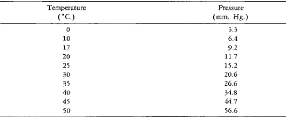
T A B L E 33
V A P O R PRESSURE O F GLACIAL A C E T I C A c i Da>4 2
Temperature Pressure
( ° C ) (mm. Hg.)
0 3.3
10 6.4
17 9.2
20 11.7
25 15.2
30 20.6
35 26.6
40 34.8
45 44.7
50 56.6
a For obtaining intermediate points, a plot of temperature vs. pressure should be made and the correct value taken from the curve, such as Fig. 200.
X Ε Ε 6 0
Ο 1 0 2 0 3 0 4 0 5 0 ° C
FIG. 200. Curve showing vapor pressure of acetic acid at various room temperatures.
Example:
11.981 mg. of sample in acetic acid was used. The following conditions existed:
= burette reading (mercury levels in burette and manometer equal) before re
action of sample = 5.54 ml.
Ti = temperature before reaction of sample = 24.1° C. or 297.26° Κ
P. = barometric reading before reaction of sample = 766.0 mm. uncorrected or 763.0 mm. corrected
Pg. = vapor pressure of the solvent at 24.1° C. = ^ 15 mm. (from Table 3 3 ) (also from Fig. 2 0 0 )
J /f = burette reading (mercury levels in the burette and manometer equal) after reaction of sample = 3.00 ml.
19. Unsaturation (Double Bonds) 504
Tt = temperature after reaction of sample = 24.1° C. or 297.26° Κ
Pf =z barometric reading after reaction of sample = 766.0 mm. uncorrected or 763.0 mm. corrected
Pg f = vapor pressure of the solvent at 24.1° C. = ^ 15 mm. (from Table 3 3 ) (also from Fig. 2 0 0 )
V1 = burette reading, after reaction of sample with mercury in the burette and manometer at different levels = 2.00 ml.
P1 = difference in mercury levels of the burette and manometer to obtain V1 = 29.0 mm.
_ 7 6 3 , 0 X 3.00 — 763.0 X 2.00 — 29.0 X 2.00 29.0
= 24.31 ml.
(763.0 — 1 5 ) X ( 5 . 5 4 + 24.31) X 273.16 297.26 X 760.0
748.0 X 29.85 X 273.16
= 27.00 ml.
and 297.26 χ 760.0
(763.0 — 1 5 ) X ( 3 . 0 0 + 24.31) X 273.16 297.26 X 760.0
748.0 X 27.31 X 273.16 297.26 χ 760.0 Vf° — V? = 2.30 ml.
= 24.70 ml.
and
. τ* j , 11-981 X 22.415
. . Hydrogen number = = 116.8 2.30
T A B L E 34
ADDITIONAL INFORMATION ON R E F E R E N C E S * R E L A T E D TO C H A P T E R 19
In addition to the procedure presented in the preceding pages of this chapter, the author wishes to call to the attention of the reader the references listed in Table 34. (See statement at top of Table 4 of Chapter 1, regarding completeness of this material.) Books Ultramicro-, submicro- methods
Adkins, 2 Grunbaum and Kirk, 20 Ellis, 12
Fritz and Hammond, 16 General, miscellaneous Grant, 18, 19
Milton and Waters, 29, 30 Chaphekar and Gore, 10 Roth, 3 8 - 4 1 E l l i s> 1 2
Siggia, 48 Polgâr and Jungnickel, 35 Steyermark, 50 Steyermark, 50
* The numbers which appear after each entry in this table refer to the literature citations in the reference list at the end of the chapter.
505 Table of References
T A B L E 34 Apparatus
Budesinsky, 7 Colson, 11 Erdos, 14
Flaschka and Hochenegger, 15 Johns and Seiferle, 21 Kuhn and Moller, 23 Mead and Howton, 26 Miller and DeFord, 28 Noller and Barusch, 31 Parrette, 33
Prater and Haagen-Smit, 36 Savacool and Ullyot, 44 Schôniger, 45
Seaman, 46 Vandenheuvel, 53 Weygand and Werner, 57 Zaugg and Lauer, 59
Use of Barcroft-Warburg apparatus Barcroft, 3
Barcroft and Haldane, 4 Milton and Waters, 29 Warburg, 56
Volatile compounds Engelbrecht, 13
(Continued)
Spectrophotometric end point Miller and DeFord, 27 Karl Fischer end point
Seaman, 46
Bromination, halogenation, iodometric methods (iodine value)
Brignoni, 6
Budesinsky, and Vanickova, 8 Giraut-Erler and Grimberg, 17 Grunbaum and Kirk, 20 Komori, 22
Kuhn and Roth, 24 Miller and DeFord, 27 Phillips and Wake, 34 Rossmann, 37 Ruziczka, 43 Smits, 49 Unger, 52 Viollier, 54
Coulometric methods Leisey and Grutsch, 25 Walisch and Ashworth, 5 5 REFERENCES
1. Adams, R., and Shriner, R. L., / . Am. Chem. Soc, 45, 2171 ( 1 9 2 3 ) .
2. Adkins, H., "Reactions of Hydrogen with Organic Compounds over Copper-Chro
mium Oxide and Nickel Catalysts," Univ. Wisconsin Press, Madison, Wisconsin, 1937.
3. Barcroft, J . , / . Physiol. (London), 37, 12 ( 1 9 0 8 ) .
4. Barcroft, J . , and Haldane, J . S., / . Physiol. (London), 28, 232 ( 1 9 0 2 ) . 5. Brancone, L. M., Personal communication, 1947.
6. Brignoni, J . M., Quim. ind. (Montevideo), 1, 13 ( 1 9 4 6 ) .
7. Budesinsky, B . , Collection Czechoslov. Chem. Communs., 24, 2948 ( 1 9 5 9 ) . 8. Budesinsky, B . , and Vanickovâ, E., Ceskoslov. farm., 6, 305 ( 1 9 5 7 ) . 9. Carothers, W . H., and Adams, R., / . Am. Chem. Soc, 45, 1071 ( 1 9 2 3 ) . 10. Chaphekar, M. R., and Gore, T . S., Mikrochim. Acta, p. 664 ( 1 9 5 9 ) . 11. Colson, A. F., Analyst, 79, 298 ( 1 9 5 4 ) .
12. Ellis, C , "Hydrogénation of Organic Substances, Including Fats and Fuels," 3rd ed., Van Nostrand, New York, 1930.
13. Engelbrecht, R. M., Anal. Chem., 29, 1556 ( 1 9 5 7 ) .
14. Erdos, J . , Mikroche?nie ver. Mikrochim. Acta, 35, 236 ( 1 9 5 0 ) . 15. Flaschka, H., and Hochenegger, M., Mikrochim. Acta, p. 586 ( 1 9 5 7 ) .
16. Fritz, J . S., and Hammond, G. S., "Qualitative Organic Analysis," Wiley, New York,
19. Unsaturation (Double Bonds) 506
and Chapman & Hall, London, 1957.
17. Giraut-Erler, L., and Grimberg, J . , Ann. biol. clin. (Paris), 7, 127 ( 1 9 4 9 ) .
18. Grant, J . , "Quantitative Organic Microanalysis, Based on the Methods of Fritz Pregl," 4th ed., Blakiston, Philadelphia, Pennsylvania, 1946.
19. Grant, J . , "Quantitative Organic Microanalysis," 5th ed., Blakiston, Philadelphia, Pennsylvania, 1951.
20. Grunbaum, B . W., and Kirk, P. L., Mikrochemie ver. Mikrochim. Acta, 39, 268 ( 1 9 5 2 ) .
21. Johns, I. B . , and Seiferle, E. J . , Ind. Eng. Chem., Anal. Ed., 13, 841 ( 1 9 4 1 ) . 22. Komori, S., Kôgyô Kagaku Zasshi, 51, 120 ( 1 9 4 8 ) .
23. Kuhn, R., and Môller, E. F., Angew. Chem., 47, 145 ( 1 9 3 4 ) . 24. Kuhn, R., and Roth, H., Ber., 65, 1285 ( 1 9 3 2 ) .
25. Leisey, F. Α., and Grutsch, J . F., Anal. Chem., 28, 1553 ( 1 9 5 6 ) . 26. Mead, J . F., and Howton, D . R., Anal. Chem., 22, 1204 ( 1 9 5 0 ) . 27. Miller, J . W., and DeFord, D . D., Anal. Chem., 29, 475 ( 1 9 5 7 ) . 28. Miller, J . W., and DeFord, D. D., Anal. Chem., 30, 295 ( 1 9 5 8 ) .
29. Milton, R. F., and Waters, W . Α., "Methods of Quantitative Microanalysis," Long
mans, Green, New York, and Arnold, London, 1949.
30. Milton, R. F., and Waters, W . Α., "Methods of Quantitative Microanalysis," 2nd ed., Arnold, London, 1955.
31. Noller, C. R., and Barusch, M. R., Ind. Eng. Chem., Anal. Ed., 14, 907 ( 1 9 4 2 ) . 32. Ogg, C. L., and Cooper, F. J . , Anal. Chem., 21, 1400 ( 1 9 4 9 ) .
33. Parrette, R. L., Anal. Chem., 26, 237 ( 1 9 5 4 ) .
34. Phillips, W . M., and Wake, W . C , Analyst, 74, 306 ( 1 9 4 9 ) .
35. Polgâr, Α., and Jungnickel, J . L., in "Organic Analysis" ( J . Mitchell, Jr., I. M.
Kolthoff, E. S. Proskauer, and A. Weissberger, eds.), Vol. I l l , p. 203, Inter- science, 1956.
36. Prater, A. N., and Haagen-Smit, A. J . , Ind. Eng. Chem., Anal. Ed., 12, 705 ( 1 9 4 0 ) . 37. Rossmann, E., Ber., 65B, 1847 ( 1 9 3 2 ) .
38. Roth, H., "Die quantitative organische Mikroanalyse von Fritz Pregl," 4th ed., Springer, Berlin, 1935.
39. Roth, H., " F . Pregl quantitative organische Mikroanalyse," 5th ed., Springer, Wien, 1947.
40. Roth, H., "Pregl-Roth quantitative organische Mikroanalyse," 7th ed., Springer, Wien, 1958.
4 1 . Roth, H., "Quantitative Organic Microanalysis of Fritz Pregl," 3rd éd., ( Ε . B . Daw, trans. 4th German ed.), Blakiston, Philadelphia, Pennsylvania, 1937.
42. Roth, W . Α., and Scheel, K., "Landolt-Bôrnstein, Physikalisch-Chemische Tabellen,"
5th ed., p. 1365, Springer, Berlin, 1923.
43. Ruziczka, W., Mikrochemie ver. Mikrochim. Acta, 36/37, 924 ( 1 9 5 1 ) . 44. Savacool, R. V., and Ullyot, G. E., Anal. Chem., 24, 714 ( 1 9 5 2 ) . 45. Schôniger, W., Mikrochemie ver. Mikrochim. Acta, 38, 132 ( 1 9 5 1 ) . 46. Seaman, W . , Anal. Chem., 30, 1840 ( 1 9 5 8 ) .
47. Shriner, R. L. and Adams, R., / . Am. Chem. Soc, 46, 1683 ( 1 9 2 4 ) .
48. Siggia, S., "Quantitative Organic Analysis via Functional Groups," 2nd ed., Wiley, New York, and Chapman & Hall, London, 1954.
49. Smits, R., Rec trav. chim., 78, 713 ( 1 9 5 9 ) .
50. Steyermark, Al, "Quantitative Organic Microanalysis," Blakiston, Philadelphia, Penn
sylvania, 1951.
51. Thomas, Arthur H., Company, Philadelphia, Pennsylvania.
507 References
52. Unger, Ε. H., Anal. Chem., 30, 375 ( 1 9 5 8 ) . 53. Vandenheuvel, F. Α., Anal. Chem., 24, 847 ( 1 9 5 2 ) .
54. Viollier, G., Help. Physiol, et Pharmacol. Acta, 7, C26 ( 1 9 4 9 ) . 55. Walisch, W . , and Ashworth, M. R. F., Mikrochim. Acta, p. 497 ( 1 9 5 9 ) . 56. Warburg, O., Biochem. Z., 142, 317 ( 1 9 2 3 ) .
57. Weygand, C , and Werner, Α., / . prakt. Chem., 149, 330 ( 1 9 3 7 ) . 58. Willits, C. O., and Ogg, C. L., Personal communication, 1949.
59. Zaugg, Η. E., and Lauer, W . M., Anal. Chem., 20, 1022 ( 1 9 4 8 ) .