Microdeterminations Carried Out on the Van Slyke Manometric Apparatus
I. MANOMETRIC CARBON DETERMINATION
II. MANOMETRIC DETERMINATION OF PRIMARY A M I N O NITROGEN IN ALIPHATIC a-AMINO ACIDS
III. OTHER DETERMINATIONS USING THIS APPARATUS The Van Slyke manometric blood gas apparatus shown in Figs. 184 and 185 was first used, as the name implies, for the determination of the gases in b l o o d .3'2 4'9 7 Since that time it has been applied to a number of microchemical determinations as shown in the following pages of this chapter.
/. MANOMETRIC CARBON DETERMINATION92
The manometric carbon determination is based on the oxidation of the organic compound to carbon dioxide and the measuring of the pressure exerted by this gas at a constant volume and at room temperature.
The oxidation is effected by a wet combustion mixture consisting of fuming sulfuric, chromic, phosphoric and iodic acids. The resulting carbon dioxide and halogens, if present, are absorbed in alkaline hydrazine solution (the hydrazine being present to reduce the halogens—see Chapter 1 1 ) and the unabsorbed gases (oxygen and nitrogen) are ejected. The absorbed carbon dioxide is liberated by means of lactic acid and the pressure exerted by it is measured. ( T h e other acidic components being stronger acids than lactic remain as salts in the alkaline solution.) The liberated carbon dioxide is reabsorbed and the residual pressure in the apparatus noted. The difference between these readings is the pressure due to the carbon dioxide obtained by combustion of the sample. Elements which interfere with, or require modifica
tion of, the dry combustion (Chapter 9 ) have no effect on the manometric method. The reactions are represented by the following:
Oxidation
( a ) Organic compounds » C 02 + H20 + Halogens - f etc.
(C, H, O, Halogen, etc.)
454
NaOH
( b ) C 02 - f Halogens > N a2C Os + N a X
N H2. N H2 " ( X = Halogens) Lactic
( c ) N a2C 03 > C 02 acid NaOH
( d ) C 02 > N a2C 03
This method, using the same manometric apparatus, is applicable for samples containing anywhere from 0 . 3 - 1 5 mg. of carbon. However, for handling the larger amounts some of the accessory pieces are modified as are the technique and the quantities of reagents used. This chapter deals with the analysis of samples containing carbon in the amounts of from 0.3-0.7 mg. and from 2 - 3 . 5 mg., which Van Slyke termed for the sake of convenience,
"submicroanalysis" and "microanalysis," respectively. All of the pieces of apparatus for these ranges are the same and there are practically no differences in either the amounts of reagents used or the technique. For the analysis of the amounts of carbon in the range of 8 - 1 5 mg. which the above author termed "macroanalysis," the reader is referred to the original publication.9 2
The procedure outlined below appears to be given in great detail. However, this is necessary since it is one in which the right stopcock must be turned to its correct position at the right time or the determination is ruined. In spite of this, the average person is able to do precision work after one or two days' practice and most chemists find the technique to be a fascinating one. The determination has the advantages ( a ) that it may be completed in about 2 0 minutes; ( b ) that there appear to be no interfering elements and ( c ) that
"submicro" quantities may be determined. On the other hand, it gives only the carbon values instead of both carbon and hydrogen as does the dry com
bustion method (Chapter 9 ) .
Reagents
POTASSIUM IODATE
Reagent grade of potassium iodate powder is used in the combustion tube to furnish the iodic acid.
COMBUSTION FLUID (Caution: Highly Corrosive)
In a 1-liter Pyrex1 5 Erlenmeyer ground glass-stoppered flask are placed 25 grams of anhydrous chromic acid ( C r 03) and 5 grams of potassium iodate, both reagent grade, followed by 167 ml. of pure syrupy phosphoric acid (sp. gr., 1.7), and 333 ml. of fuming sulfuric acid ( 2 0 % excess S 03) . The stopper is left off and the contents of the flask heated slowly to 1 5 0 ° C , with occa-
sional rotation to dissolve the chromic acid and to aid the escape of the carbon dioxide formed by the oxidation of traces of organic material present.
The flask is covered by an inverted beaker to prevent contamination and allowed to cool to room temperature. Then the stopper of the flask is inserted and covered by the beaker as an added means of protection from dust. This flask should be used for storage purposes and should be opened to the atmos
phere only when used to fill a small bottle from which the mixture is poured during the course of the determination. This small bottle should be of the type shown in Fig. 186, C. It is equipped with both a ground stopper and a stopper cover, the latter being joined to the bottle below the neck by means of ground surfaces. In this manner the combustion fluid is allowed to absorb a minimum of moisture from the atmosphere. The fluid in this small bottle should be replaced quite frequently, discarding the mixture after several days' use. This is done as a precaution, since absorbed water vapor leads to low carbon values.*
ALKALINE HYDRAZINE
A 0 . 5 N sodium hydroxide plus 03M hydrazine solution, approximately carbon dioxide free, is prepared as follows: A concentrated solution of sodium hy-
* In personal communications (June 14, 1949 and November 10, 1 9 5 0 ) , Doctor Van Slyke advised the author that he is now replacing the combustion fluid by the following:
A. F o r Carbohydrate and Polyhydroxl Alcohols: SOLID REAGENT. One part of potassium dichromate to ten parts by weight of potassium iodate. These are ground together. (See below.)
LIQUID REAGENT. Fifty ml. reagent grade of concentrated sulfuric acid (sp. gr. 1.84), 50 ml. of reagent grade of syrupy phosphoric acid (sp. gr. 1.70-1.72) and 1.5 grams of potassium iodate are heated at 1 6 0 ° - 1 9 0 ° C. until the solid is dissolved (the mixture is saturated with potassium iodate). The heating destroys any organic material which might be present as a contaminant.
B. Combustion Reagents for General Use (Substances Other than Carbohydrates and Polyhydroxyl Alcohols) : SOLID REAGENT. One part of potassium dichromate to two parts of potassium iodate by weight. The two substances are ground together. (See below.)
LIQUID REAGENT. Sixty-seven ml. reagent grade of fuming sulfuric acid ( 2 0 % excess SOg), 33 ml. of reagent grade of syrupy phosphoric acid (sp. gr. 1.70-1.72), and one gram of potassium iodate. The mixture is heated at 1 6 0 ° - 1 9 0 ° C. until the solid is dis
solved. (See above.)
(Note: Since so-called fuming grades of sulfuric acid may vary considerably in the excess S 03 content, Van Slyke advocates standardization by titration with alkali of fuming acids of 10 and 3 0 % excess S 03 and then mixing them in the proper propor
tion to obtain 2 0 % . )
For the procedure, either of the potassium dichromate-potassium iodate mixtures is added to the dry sample in the following proportions:
0.15 gram for the "submicro" combustions (0.1-0.7 mg. of carbon).
0.30 gram for "micro" combustions (0.7-3.5 mg. of carbon). The liquid reagent is added in the same volume and manner described under Procedure.
droxide ( 1 8 - 2 0 N ) is prepared, stoppered, and then stored until the carbonate has been allowed to settle out.* A little over a liter of distilled water is acidified with a few drops of dilute acid and boiled for a few minutes to expel any dissolved carbon dioxide. The water is allowed to cool under the protection of an Ascarite tube to prevent the reabsorption of the gas. Enough concen
trated, carbonate-free, sodium hydroxide ( 1 8 - 2 0 N ) is decanted into a portion of the boiled-out distilled water to make a solution of slightly greater con
centration than 0.815N. An aliquot portion of this is titrated with standard acid to determine the true normality. Then the bulk of the solution is diluted with whatever amount of boiled-out distilled water that may be necessary to bring the concentration to 0.815 ± 0.005N. This solution is then stored in a paraffin-lined aspirator bottle protected by a stopper into which is inserted an Ascarite8 3 drying tube. (Note: Standard 0.815N sodium hydroxide solu
tion, approximately carbon dioxide free, is now commercially available.2 6) Five grams of hydrazine sulfate crystals are placed into a 250-ml. volumetric flask (or if it is desirable to prepare some other volume of solution, 2 grams of hydrazine sulfate is added for each 100-ml. capacity of the flask used). The aspirator tip of the paraffin-lined bottle containing the 0.815N sodium hy
droxide is washed with distilled water and then a few milliliters of the alkali is run out and discarded as precautions against collecting carbonate. The aspirator tip is inserted down into the neck of the 250-ml. volumetric flask and 0.815N alkali added, while the flask is whirled to dissolve the crystals.
The tip is kept in place until the liquid is added up to the 250-ml. mark and is then removed. The resulting 0.5N sodium hydroxide plus 03M hy
drazine solution is stoppered and mixed well. The stopper is removed from the 250-ml. volumetric flask and the solution sucked up immediately into a rubber-tipped stopcock cylinder of the type shown in Fig. 186, D, pro
tected by an Ascaritef tube (see description below). For this purpose, an extra length of clean rubber tubing is attached over the rubber tip on the stopcock cylinder and the free end is inserted to the bottom of the flask so that solution is withdrawn at this point. Since the top layers of the alkali might have absorbed carbon dioxide again during the manipulation, about one-fifth of the solution is left in the volumetric flask and discarded. After removal of the tubing, the rubber tip of the stopcock cylinder is immersed in mercury, covered by normal sulfuric acid, as shown in Fig. 186, D. The alkaline hydrazine solution should be dated and used for a maximum of one month, after which it should be discarded. The solution in the stopcock cylinder is always kept alongside the manometric apparatus so that the temperature of the solution is the same as that of the water-jacketed extraction chamber—
see below.
* This solution is now commercially available.1-2 6 t Or soda-lime.
LACTIC ACID, 2N
One volume of reagent grade concentrated lactic acid, sp. gr. 1.20, is diluted with four volumes of water. An aliquot portion of this is titrated with standard alkali using phenolphthalein as the indicator, after which either more water or lactic acid is added to the bulk of the solution to make it 2N. (Note: 2N lactic acid solution is now commercially available.2 6)
SODIUM HYDROXIDE SOLUTION, APPROXIMATELY 5N
A sodium hydroxide solution, approximately 5N, is used to reabsorb the liberated carbon dioxide. This need not be carbonate free. It may be stored in a stopcock cylinder of the type shown in Fig. 186, D but minus the rubber tip on the delivery tube.
SYRUPY PHOSPHORIC ACID, SP. GR., 1.7
This material is used for lubricating the stopcock on the dropping funnel (Figs. 187 and 188, F), and the ground joint between the dropping funnel and the combustion tube (Figs. 187 and 188, T ) .
MERCURY
About 20 pounds of triple distilled mercury is needed for filling the mano
metric system. Note: A trace of glycerol or diethylene glycol should be added through the stopcock at the top of the manometer to absorb water.
STOPCOCK GREASE
A special stopcock grease for lubricating all of the stopcocks on the mano
metric apparatus (three on the manometer, one on the chamber) and on the dropping cylinder is commercially available.1 8'8 3 In addition, the author has found Sisco No. 300 stopcock grease7 1-8 2 to be equally good for this purpose.
A , 1 8 , 5 1 , 7 0 , 7 1 , 8 0 , 8 3 , 9 2
Apparatus
The manometric apparatus used is shown in Figs. 184, 185, 187, and 188, while the accessory apparatus are shown in Figs. 186 and 189.
MANOMETRIC APPARATUS
The manometric apparatus consists of a water-jacketed extraction chamber, C, manometer and leveling bulb, L (Figs. 187 and 1 8 8 ) .
The extraction chamber is water-jacketed as a means of maintaining more constant temperature. Sealed to the upper portion of the chamber is an inlet cup, E. Between the chamber and the cup is a three-way stopcock, b. One lead of the three-way stopcock connects the chamber to the cup and the other
joins the chamber when desired to the combustion tube by means of the connecting tube, Q. The chamber proper is composed of three connected bulbs, graduated in size, the smallest at the top and the largest at the bottom.
Graduations appear above the smallest bulb, between the first and second, and the second and third bulbs, and below the third, being marked respectively 0.5, 2.0, 10.0, and 50.0 ml. An electric shaking (or magnetic stirring) device
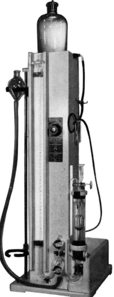
FIG. 184. Sargent model of Van Slyke manometric blood gas apparatus, shaker type.
is attached. By this means, the contents of the chamber may be shaken (or stirred) violently. A heavy-walled rubber tube, approximately 25 mm. O.D., 5 mm. I.D., (or ball and socket joint) connects the extraction chamber to the manometer.
The manometer is equipped with three stopcocks, two of which are used to fill it with mercury and the third, a (Figs. 187 and 1 8 8 ) is used to control the flow of mercury which, in turn, controls the volume of gas in the chamber.
Below the stopcock, a, is attached a section of heavy-walled rubber tubing whose opposite end is connected to the leveling bulb, L, which is used as a reservoir for the mercury.
The assembled manometric apparatus nlled with mercury should not be allowed to stand indefinitely with all of the stopcocks closed, or breakage
FIG. 1 8 5 . Thomas model of Van Slyke manometric blood gas apparatus, magnetic stirring.
is apt to occur due to expansion of the mercury if the temperature in the room rises. The stopcock, a, should be left open to prevent this.
STAND FOR MANOMETRIC APPARATUS
The extraction chamber, C, manometer, and leveling bulb, L, are mounted on a stand, made either of wood, plastic, or metal. At the top is a small platform (or other means) for mounting the distilled water reservoir used
for washing the extraction chamber between analyses. On the left side of the stand are mounted two cut-away rings for holding the leveling bulb, L.
The upper ring holds the bulb above the top of the cup, E, attached to the extraction chamber, and the lower ring holds the bulb so that the mercury surface in it stands at about the level of the 50-ml. mark on the extraction chamber. The stand is provided with an illuminated background for that
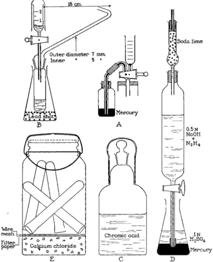
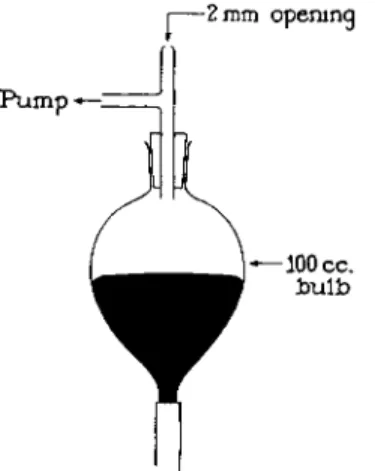
FIG. 186. Accessory parts to manometric apparatus. (A) Bottle of mercury arranged for sealing capillary of stopcock, b, on extraction chamber ( F i g . 1 8 7 ) . (B) 100-ml. flask weighted with lead shot serving as a stand for combustion tube after analysis. (C) 100- ml. bottle for storage of combustion fluid, provided with cover and ground joint to prevent access of moisture. ( D ) Stopcock cylinder containing alkaline hydrazine solution with tip protected from atmospheric carbon dioxide by sulfuric acid and mercury. (E) Fruit jar for storing clean combustion tubes.
portion of the manometer which is graduated. The illumination should be on for just long enough to make a reading or the mercury will expand from the heat. For this reason, only fluorescent (or internal reflection) lighting should be used. With some models (Fig. 1 8 4 ) the water jacket surrounding the extraction chamber is held in a clamp which in turn is attached to an electric motor-driven eccentric. This provides the means of shaking the chamber
Soda lime
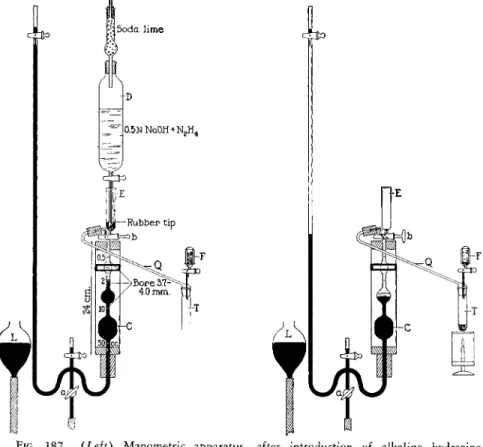
FIG. 1 8 7 . {Left) Manometric apparatus—after introduction of alkaline hydrazine into chamber and before start of combustion.
FIG. 1 8 8 . {Right) Manometric apparatus—at start of combustion but before evolu
tion of carbon dioxide and oxygen has begun.
vigorously to and fro at a tempo of 250 to 300 times per minute. With other models (Fig. 1 8 5 ) the same rate of stirring is accomplished by means of a magnetic stirrer with concealed magnetic stirring apparatus.
CONNECTING TUBE AND CUP
The connecting tube, Q (Figs. 187 and 1 8 8 ) , and 2-ml. graduated cup, F (plus stopcock) (also see B, Fig. 1 8 6 ) , are sealed together through an inter-
changeable ground joint which in turn fits the top of the combustion tube.
The tube, Q, connects via heavy-walled rubber tubing, approximately 25 mm.
O.D., 4 mm. I.D. (or, if desired, an interchangeable ground joint) the com
bustion tube to the extraction chamber, while the cup, F, is used for the addition of combustion fluid, via the stopcock to the sample. The cup is provided with a cover made from the bottom section of a test tube. A 100-
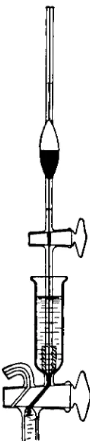
FIG. 189. Stopcock pipette, showing attached rubber tip and method of introducing liquid into extraction chamber.
ml. Pyrex1 5 flask, weighted with lead shot, serves as a stand for the com
bination when not in use (see B, Fig. 1 8 6 ) .
COMBUSTION TUBE
The combustion tube is made of Pyrex1 5 glass and is equipped with an inter
changeable ground joint at the top which fits the corresponding member of the connecting tube and cup (see Figs. 187 and 188, T ) .
SMALL MERCURY BOTTLE WITH CAPILLARY
A small bottle, having a loosely fitted capillary inserted through a stopper, is filled with mercury as shown in A, Fig. 186. This is used for making mercury seals in the capillary of the stopcock above the chamber. Connection is made to the chamber through the same heavy-walled rubber tubing used when the combustion tube is attached via the tube, Q. (Note: If an interchangeable ground joint is used instead of the heavy-walled rubber tubing, the capillary with the small mercury bottle must also be provided with a ground joint to fit.)
STOPCOCK CYLINDER
The stopcock cylinder shown in Figs. 186 and 187, D, is used as a reservoir for the alkaline hydrazine and for transferring this solution to the extraction chamber. The delivery end is fitted with a special rubber tip (see below) by means of which a gas-tight connection is made with the extraction chamber.
RUBBER TIPS
Rubber tips are used on the delivery ends of the stopcock cylinder (above) and on the stopcock pipettes (see below) to effect a gas-tight connection between them and the extraction chamber. They are commercially available from the sources supplying the manometric apparatus. They may be made by cutting a ring about one cm. wide from a pliable rubber tube with a bore of 1-2 mm. and walls of 3 - 4 mm. thick. The ring is then tapered at one end by grinding down the outer edge with sandpaper or a grinding wheel so that it will fit into the bottom of the cup, E, above the extraction chamber.
Considerate care must be exercised in the grinding so that the taper is smooth and gives a good gas-tight fit when used.
STOPCOCK PIPETTE97
A one-ml. capacity stopcock pipette of the type shown in Fig. 189 is required for introducing the lactic acid into the extraction chamber. It is graduated with two marks, the volume between being equal to one ml. The delivery end is fitted with a rubber tip (see above).
MERCURY DROPPING BOTTLE
A small bottle from which fractions of a milliliter of mercury may be poured is used in making mercury seals through the cup, E} at the top of the ex
traction chamber. A one-ounce bottle supplied with a one-hole rubber stopper containing a section of glass capillary tubing (1-mm. bore) is quite satisfactory.
HEAVY-WALLED RUBBER TUBING
Heavy-walled pliable rubber tubing, approximately 25 mm. O.D. and 4 mm.
I.D. is used for connecting the extraction chamber to the manometer and
to the combustion tube via the glass connecting tube, Q, unless interchangeable ground joints are present.
DISTILLED WATER RESERVOIR
A distilled water reservoir of 1- or 2-liter capacity is used for washing the manometric apparatus. A Mariotte bottle (Fig. 129, Chapter 9 ) is quite satis
factory for this purpose. It is placed on a platform at the top of the manometer stand so that the water will flow by gravity into the cup, Ε (Fig. 1 8 7 ) when needed.
WATER SUCTION SYSTEM
A water suction pump, protected by a trap of 1-liter capacity, is used for sucking off the solutions and wash water from the cup, E. The tubing attached to this is fitted with a rubber-tipped glass capillary to facilitate the washing.
ELECTRIC HEATER OR MICROBURNER
Same as used in Chapter 16 (see Figs. 180 and 1 8 1 ) , the electric one being preferred.2 3-8 3
η I 8 0 , 9 2
Procedure
A synopsis of the procedure may be given by the following:
1. Connection of combustion tube and sample to the manometric apparatus 2. Evacuation of the combustion tube
3. Ejection of air from the combustion tube
4. Introduction of alkaline hydrazine followed by mercury seal 5. Combustion
6. Absorption of carbon dioxide
7. Disconnection of the combustion tube followed by mercury seal 8. Ejection of unabsorbed gases followed by mercury seal
9. Extraction of carbon dioxide (mercury seal) 10. Reading of the p1 value
11. Reabsorption of the carbon dioxide (mercury seal) 12. Reading of the p2 value.
CONNECTING COMBUSTION TUBE WITH EXTRACTION CHAMBER
The sample is weighed in a platinum boat (see Chapter 3 ) and placed in a clean dry combustion tube, Τ (Figs. 187 and 1 8 8 ) . [ T h e size of the sample is governed by the percentage of carbon since not more than 3.5 mg. of this element may be present or the manometer cannot be read. The platinum boat
is useful in preventing bumping. I f the sample is weighed by difference using a charging tube (see Chapter 3 ) , a few platinum tetrahedra should be added for the above purpose.] For a "microanalysis" ( 2 - 3 . 5 mg. C ) , 200 mg. of potassium iodate* is added to the sample. (For a "submicroanalysis," 0 . 3 - 0.7 mg. C, only 100 mg. of potassium iodate is added.) The combustion tube is held in an almost horizontal position and a ring of syrupy phosphoric acid is drawn around the upper part of the ground joint with the aid of a glass rod or medicine dropper. The connecting tube, Q, and cup, F, com
bination is inserted into the combustion tube. ( T h e stopcock of the above combination is also lubricated with syrupy phosphoric acid and is left in the closed position.) The leveling bulb, L (Figs. 187 and 1 8 8 ) , is placed in the upper ring of the stand, the stopcock, a, is opened and the stopcock, b, is turned so that mercury completely fills the extraction chamber, C, and several milliliters pass into the cup, E. The stopcock, b, is then closed and the stop
cock, a, is left open. The combustion tube-connecting tube-cup combination (T-Q-F) is joined to the extraction chamber, C, by means of a section of the heavy-walled tubing, effecting a glass-to-glass connection—(or if preferred, an interchangeable ground joint may be used at this point, as is the prefer
ence of the author). Slightly more than 2 ml. of fresh combustion fluid is placed in the cup, F, which then is covered to protect the fluid from moisture.
PRELIMINARY EJECTION OF AIR
The leveling bulb, L, is placed in the lower ring on the stand. Then the stop
cock, b, at the top of the extraction chamber, C, is turned so as to connect the chamber with the combustion tube, T. The mercury level in the chamber falls immediately since air is drawn from the combustion tube. The leveling bulb, L, then is removed from the lower ring, held in the left hand, and lowered below the table top so that mercury is drawn out of the chamber.
When the mercury level in the chamber, C, has reached the 50-ml. mark, the stopcock, a, is closed, and the leveling bulb, L, is returned to the upper ring of the stand. The stopcock, b, is closed and then stopcock, a, is opened. This admits mercury to the chamber, C, and compresses the trapped air. Then the stopcock, b, is turned so that the trapped air is forced out through the cup, E, along with several milliliters of mercury. Then the stopcock, b, is closed. [Ejec
tion of the air diminishes to insignificance the part of the blank (see below) that is due to atmospheric carbon dioxide present in the apparatus when the combustion is begun. It also removes the inert gases thereby increasing the efficiency of each subsequent transfer (see below) since there are fewer in
terfering molecules present].
* See footnote, p. 456, for Combustion Fluid regarding the use of potassium dichromate at this point.
MEASUREMENT OF ALKALINE
HYDRAZINE SOLUTION INTO EXTRACTION CHAMBER
The leveling bulb, L, is placed in the lower ring of the stand. The rubber- tipped stopcock cylinder, D (Figs. 186 and 1 8 7 ) , containing the alkaline hydrazine solution is placed so that the delivery end makes a gas-tight con
tact with the bottom of the cup, E, which contains a few milliliters of mer
cury for sealing purposes (see Fig. 1 8 7 ) . The stopcock on the cylinder is opened. ( N o solution flows thusly since the rubber-tipped end is pressed tightly against the bottom of the cup, E.) The stopcock, b, is opened slightly so that alkaline hydrazine solution slowly enters the extraction chamber.
When the alkaline solution is about one mm. above the 2-ml. mark in the extraction chamber, the stopcock, b, is closed and so is that on the cylinder, after which the latter is replaced in its holder with the tip protected from atmospheric carbon dioxide—D (Fig. 1 8 6 ) . The stopcock, b, is opened and closed quickly so that both the alkali in the capillary of the cock and enough mercury for a seal* are drawn into the chamber. The alkali which was con
tained in the capillary is enough to bring the volume of solution in the chamber to exactly 2 ml. The cup, E, is washed with several portions of water, each of which is removed by the water suction pump. ( A t no time should alkali be allowed to remain in the cup where it would absorb carbon dioxide and be carried back into the chamber.)
COMBUSTION
The leveling bulb, L, is removed from the lower ring and held in the left- hand below the table top. Mercury is drawn out of the chamber, C, and the manometer until the mercury level in the manometer stands a little below the level of the 2-ml. mark on the chamber, C. Then the stopcock, a, is closed and the leveling bulb, L, is placed in the lower ring of the stand and left in this position until the combustion is finished. (This position brings the mer
cury surface in the bulb, L, to about the level of the 50-ml. mark on the chamber, C.) The stopcock, b, is turned to connect the chamber, C, with the combustion tube, Τ (see Fig. 1 8 8 ) . The stopcock below the cup, F, is carefully opened to allow 2 f ml. of fresh combustion fluid to slowly run into the com
bustion tube, T, making certain that no air is allowed to enter the system.
For this reason, slightly more than the required amount of combustion fluid was added to the cup, F, and the slight excess is allowed to remain in the capillary above the stopcock below the cup.
* At no time should the manometric apparatus be allowed to remain under reduced pressure (leveling bulb, L, in the lower ring) unless the capillaries of the stopcock, b, are filled with mercury as a seal.
f Two ml. for a "microanalysis" ( 2 - 3 . 5 mg. of carbon) or 1.5 ml. for a "sub- microanalysis" ( 0 . 3 - 0 . 7 mg. carbon).
An electric heater or microburner is used to heat the contents of the com
bustion tube. The heat is applied cautiously at first so that the foam collar which forms in the tube is not more than 2 cm. high on the liquid. Within one or two minutes the fluid is brought to boiling. As carbon dioxide and oxygen are evolved, the mercury falls in the extraction chamber, C, and rises in the manometer (Fig. 1 8 8 ) . During this stage the stopcock, a, is opened slightly and closed every few seconds to admit mercury from the leveling bulb, L, into the chamber, C, and to keep the gas space in the extraction chamber, C, at about 10 ml. Within about one minute from the beginning of the heating, enough gas has been evolved to press the mercury in the manometer up to its top and to permit the stopcock, a, to be opened com
pletely without causing a backflow of the alkaline solution from the chamber, C, to the combustion tube, Τ. Then the stopcock, a, is left fully open during the rest of the combustion with the system under a pressure of about 600 mm.
of mercury. Vigorous boiling* is continued at this pressure for 1.5 minutes to complete the combustion. During this interval, foam should fill i/3 to l /2 of the tube, T.) This completes the combustion.
ABSORPTION OF CARBON DIOXIDE BY THE ALKALINE HYDRAZINE IN THE EXTRACTION CHAMBER
After the completion of the combustion above, the heater or flame is left in place under the combustion tube and the leveling bulb, L, is lowered below the table top. This causes mercury to fall in the chamber, C, and the bulb is held in this position until the mercury has reached the 50-ml. mark.
The combustion fluid boils vigorously under the reduced pressure, almost the entire tube being filled with foam. The leveling bulb is quickly raised which causes mercury to return to the chamber, C. During this compressive stage, the combustion fluid does not boil. As soon as the gas space in the chamber, C, has been compressed to about 7 ml., the leveling bulb is quickly lowered below the table top until the mercury in the chamber falls again to the 50-ml. mark. This process of alternate expansion and compression should be repeated rapidly 25 times. The stopcock, a, is closed then while the gas still is expanded {mercury at the 50-ml. mark), after which the leveling bulb, L, is returned to the lower ring. The total time required for the 25 excursions should be about 4 minutes, f
* Gentle boiling may yield low results.
f When many determinations are carried out in succession, the alternate lowering and raising of the bulb may be substituted by alternately applying and releasing of suction at the top of the leveling bulb, L, while it is in the lower ring of the stand. For this purpose, a T- or Y-tube is inserted by means of a one-hole stopper into the neck of the leveling bulb (Fig. 1 9 0 ) . One of the extending tubes is attached directly to a pump without an intermediate trap. The suction is applied and the finger is used to close the free tube. Mercury is drawn from the chamber into the bulb but rapidly returns when
The heater or flame is then removed from under the combustion tube, T, the stopcock, b, is closed, and the connecting tube, Q, is disconnected from the chamber, C (after releasing the vacuum in the combustion tube by opening the stopcock below the cup, F). ( T h e combustion tube, Γ , connecting tube, O, and cup, F, should be washed and thoroughly dried in an oven at 120° C.
to prepare them for the next analysis. The practice of using the connecting tube and cup for the next determination is a dangerous one since a drop of combustion fluid is apt to fall upon the sample during the preliminary evacua
tion.) Immediately after removal of the connecting tube, Q, the curved capillary of the stopcock, b, must be filled with mercury. This is done by attaching the small bottle of mercury, equipped with a loose-fitting capillary,
j — 2 mm opening
P u m p — = |
FIG. 190. Leveling bulb attachment—when suction pump is used to raise and lower mercury.
as shown in Fig. 186, A, and carefully opening the stopcock, b, so that mercury fills the cock and a few drops fall into the extraction chamber. The bottle is removed and the excess mercury in the capillary is drawn into the chamber leaving just enough mercury to fill the capillary about one cm. above the stopcock, b, which is then closed. ( I f the excess mercury is not drawn in, it will be thrown on the table top when subsequent shaking is done. The small volume of air admitted to the chamber in the process of making the mercury seal at this point is of no consequence since it will be ejected with the unabsorbed gases as described below.) The stopcock, a, is then opened and the leveling bulb, L, is placed in the upper ring putting the gases in the extraction chamber under positive pressure.
the finger is removed from the tube and the suction is broken. When this method is used it is desirable to have a bulb, L, of not over 100-ml capacity and to have enough mercury present in the system so that the bulb is nearly filled when all of the mercury is withdrawn from the extraction chamber.
EJECTION OF UNABSORBED GASES
The stopcock, b, is opened carefully allowing the gases to escape through the mercury pool in the cup, E, until the alkaline solution just reaches the bottom of the stopcock, b. The stopcock, b, is then closed and the leveling bulb, L, placed in the lower ring of the stand. The stopcock, b, is quickly opened and closed so as to make a mercury seal in the capillary and a few drops of mercury fall into the chamber. During this process the small amount of unabsorbed gases which was in the capillary of the stopcock is drawn back into the extraction chamber. This has no influence on the determination since it is carbon dioxide free. If most of the mercury in the cup, E, was drawn into the chamber during the above process, about 1 or 2 ml. more is added so that a good seal is obtained in the subsequent operation.
EXTRACTION OF CARBON DIOXIDE AND THE READING OF Pl
A 1-ml. stopcock pipette fitted with a rubber tip is filled to the top mark with 2N lactic acid. The rubber tip is pressed against the bottom of the cup, E, and the stopcock on the pipette is opened. (The liquid in the pipette does not fall since the tip is against the closed-off capillary in the bottom of the cup.) The stopcock, b, is opened carefully to admit exactly one ml. of lactic acid and then closed. The stopcock pipette is removed. The stopcock, b, is opened and closed quickly to effect another mercury seal. The leveling bulb, L, is lowered beneath the level of the table top, drawing mercury out of the extraction chamber, C. When the mercury has fallen to the 50-ml. mark, the stopcock, a, is closed and the leveling bulb is returned to the lower ring. The extraction chamber is shaken (or stirred) for 2 0 - 3 0 seconds.* During this interval, the extracted carbon dioxide forces the mercury down below the 50-ml. mark in the chamber and the stopcock, a, is occasionally opened momentarily to keep the mercury in the extraction chamber at the 50-ml. mark.
This is accomplished by the admission of mercury each time that the stop
cock, a, is opened. Then the extraction chamber is shaken or stirred vigor
ously for 1.5 minutes to complete the extraction of the carbon dioxide from the solution. The leveling bulb, L, is placed in the upper ring and the stop
cock, a, is opened which forces mercury into the chamber, C, reducing the volume of gas to the desired mark—see below. (This reduction in volume should be accomplished rapidly within 30 or 4 0 seconds but without setting the mercury in the chamber and manometer to oscillating by jerky opening or closing of the stopcock, a.) The volume of gas in the chamber is reduced to exactly 10 ml. for ' microcombustions'' with 2 - 3 . 5 mg. of carbon (or to
* A cork is placed in the top of cup, E, during the shaking so that the mercury is not thrown out.
2 ml. for "submicrocombustions" with about one-fifth as much carbon) and the stopcock, a, is closed. Obviously, the final adjustment of the volume must be done slowly and with extreme care and it is suggested that a reading lens be used as an aid in bringing the meniscus of the aqueous solution exactly to the desired mark on the extraction chamber. The manometer reading, p1 ? is taken, making use of the illuminated background and a reading lens. [ I f it is desired to check this reading, the mercury in the chamber should be lowered again to the 50-ml. mark, the chamber shaken or stirred for one minute and the gas volume reduced again to 10 ml. (or 2 ml.) before the duplicate reading of px is made.]
REABSORPTION OF CARBON DIOXIDE AND THE READING OF p2
Now the leveling bulb, L, is placed in the lower ring. The stopcock, a, is opened and the gas is left under a slightly reduced pressure. About one ml.
of 5Ν sodium hydroxide is added on top of the mercury in the graduated cup, E. The stopcock, b, is carefully opened to admit the mercury in the cup, E, into the extraction chamber. When the mercury level has fallen into the capillary above the stopcock, b, note is made of the height of the alkali in the graduated cup. The stopcock, b, is allowed to remain slightly open until exactly 0.5 ml. of alkali (measured by difference) has entered the extraction chamber.*
About 2 ml. of mercury is added to the cup, E, and a mercury seal is made, using more than the ordinary amount of mercury to dislodge any viscous alkali that may be stuck in the tube at the top of the chamber below the stopcock, b. The excess sodium hydroxide is removed from the cup, E, by suction and then it is washed several times with distilled water to rid it of traces of alkali. The contents of the extraction chamber are mixed by lowering the leveling bulb, L, below the table top to bring the surface of the solution down to a point a little below he 10-ml. mark {not to the bottom) and then raising the leveling bulb to a point above the ring so that the pressure in the chamber is about atmospheric, as shown on the manometer. This process of lowering and raising the leveling bulb, L, is repeated three times. Then the leveling bulb is lowered below the table top to bring the solution meniscus in the chamber down a little below the 10-ml. mark (or the 2-ml. mark, at whichever point px was read), and then the stopcock, a, is closed. The leveling bulb is returned again to the upper ring. The system is allowed to stand for one minute to allow drainage of the alkali from the walls to be complete.
The stopcock, a, is carefully opened to raise the meniscus to exactly the 10-ml.
(or 2-ml.) mark and the p2 reading is made on the manometer. The tempera
ture of the water jacket is noted.
* Care must be exercised so that no trace of air enters the chamber during the admission of alkali or mercury. There must be no air bubble between the two layers.
The pressure of the carbon dioxide obtained by the combustion of the sample is given by
c0o — Pi P2 C'
where c = px — p2, obtained from a blank analysis at the same temperature as that of the regular determination. Consequently, the entire procedure must be repeated, in the absence of a sample. However, a blank analysis does not have to be performed before or after each determination. Since the value is a check on the purity of the reagents used, it need be done only occasionally if care is exercised in handling these so that they do not become contaminated from dust (in the combustion fluid) or carbon dioxide from the air (in the alkaline hydrazine or lactic acid).
WASHING THE EXTRACTION CHAMBER
It is very important that the extraction chamber be properly washed between analyses. The stopcock, a, is opened and the leveling bulb, L, is placed in the upper ring. The tubing connected to the suction device (supplied with the trap) is placed in the cup, E. The stopcock, b, is opened and the rising mercury forces the solution from the chamber into the cup, E, where it is removed immediately by the suction. When mercury is being sucked out of the cup, E, the stopcock, b, is closed. The leveling bulb is placed in the lower ring. Water is added from the reservoir at the top of the stand and the stop
cock, b, is opened carefully, admitting water to the chamber. The cup, E, is kept full of water coming from the reservoir at the same rate as it is drawn into the chamber being careful not to admit air. When no more water will enter the system (chamber, C, full) the water tube is removed and replaced by the suction one. Simultaneously, the leveling bulb is placed in the upper ring. As soon as all of the water has been forced out of the chamber together with a little mercury, the stopcock, b, is closed, the leveling bulb, L, returned to the lower ring, water admitted, etc., as above and the process repeated twice more (three washings in a l l ) . A few minutes after the final washing, any water which collects above the mercury surface at the top of the mercury- filled chamber should be forced out into the cup, E. The apparatus is then ready for the next analysis.
Calculation:
The amount of carbon present in the sample is found by multiplying the PCo9 by the factor given in Table 30.
mg. C = PC 0 2 X factor where
pc o2 ' = Pi — P2 — c (c = p1 — p2 for a blank determination)
PC O o X factor X 100
.'. = % C Wt. sample
= 8 3 . 9 4 % C Example No. 1 "Microanalysis":
In the analysis of a 3.539-mg sample, the following pressures are obtained on compressing the gas to a volume of 10 ml. at 24° C :
Volume = 10.0 ml.
Temperature = 24.0° C.
px = 468.0 mm.
p2 = 29.0 mm.
p! (blank) = 32.0 mm.) , _
1 / , , , ν P i — P2 = c = 4.0 mm.
p2 (blank) = 28.0 mm.) 1 Δ .'. PC O o = 468.0 — 29.0 — 4.0 = 435.0 mm.
From Table 30 the factor for a volume of 10 ml. at 24.0° C. is 0.006829 435.0 X 0.006829 X 100
3.539 Example No. 2 "Submicroanalysis":
In the analysis of a 1.425-mg. sample the following pressure is obtained when the gas was compressed to a volume of 2 ml. at 26.0° C :
Volume = 2.0 ml.
Temperature = 26.0° C.
p1 = 580.4 mm.
p2 = 106.5 mm.
ρ-, (blank) = 125.5 mm. ) ~„ _
1 /, , ι ν ! Pi — P2 = c = 2 0· 5 mm.
p2 (blank) = 105.00 mm.) 1 1
.'. PC 0 2 = 580.4 — 106.5 — 20.5 = 453.4 mm.
From Table 30, the factor for a volume of 2 ml. at 26.0° C. is 0.001366 453.4 X 0.001366 X 100
Λ = 4 3 . 4 6 % C 1.425
The accuracy of the determination is equal to that of the dry combustion method (Chapter 9 ) . Consequently, the allowable error is ± 0 . 3 % .
In general, with apparatus supplied by a reliable manufacturer, no cor
rection need be applied for most work. If, however, the calibration chart shows considerable deviation from the amounts marked on the extraction chamber, correction may be made by multiplying the factors given below by the ratio of the two volumes9 2 that is, by
Volume shown on correction chart Volume marked on extraction chamber
Also for most analyses the factors given in Table 30 (determined by the use of an empirical correction)9 2 are satisfactory. I f extreme accuracy is desired, a whole series of analyses on a known pure compound is made and each factor of Table 30 is multiplied by the ratio9 2:
Theoretical value for carbon Average of the found values for carbon
T A B L E 30
FACTORS FOR CARBON CALCULATION Factors Temperature
( ° C )
"Submicroanalysis"
Vol. = 2.000 ml.
"Microanalysis"
Vol. = 10.00 ml.
10 0.001474 0.007304
11 0.001466 0.007266
12 0.001458 0.007229
13 0.001451 0.007193
14 0.001444 0.007158
15 0.001437 0.007123
16 0.001430 0.007089
17 0.001424 0.007055
18 0.001417 0.007021
19 0.001410 0.006988
20 0.001403 0.006955
21 0.001397 0.006923
22 0.001390 0.006891
23 0.001384 0.006860
24 0.001378 0.006829
25 0.001372 0.006799
26 0.001366 0.006770
27 0.001360 0.006741
28 0.001354 0.006712
29 0.001349 0.006684
30 0.001343 0.006656
31 0.001337 0.006629
32 0.001332 0.006602
33 0.001327 0.006576
34 0.001321 0.006550
35 0.001316 0.006524
//. MANOMETRIC DETERMINATION OF PRIMARY AMINO NITROGEN IN THE ALIPHATIC *-AMINO
ACIDS
The aliphatic compounds containing primary amino nitrogen react with nitrous acid to yield nitrogen according to the equation :
R N H2 + H N 02 R O H + H20 + N2
Van S l y k e8 5'8 8 found that the N H2 groups in the α-amino acids react quanti
tatively in 3 - 4 minutes while the N H2 groups in other types of substances require much longer periods, sometimes many hours. The group in ammonia re-
quires about 1.5-2 hours8 5 ( 2 5 % completion after approximately 4 minutes8 6) ; in methylamine, 1 . 5 - 28 5; in urea, 88 5 ( 6 - 7 % completion after 4 m i n u t e s4 8) ; and in purines and pyrimidines from 2 - 5 hours for quantitative reactions to occur. Therefore, the α-amino groups in the aliphatic acids may be deter
mined in the presence of other forms of nitrogen. For example, with tryptophan a value for nitrogen is obtained equal to one-half of the total present while with histidine a value is obtained equal to one-third of the total, since there is but one α-amino group present in each, but a total of two and three nitrogen atoms, respectively, in these molecules.
This method, which requires about 15 minutes to complete, once the operator has mastered the technique, gives excellent results, and like the manometric carbon determination is a fascinating one to perform.
Reagents
SODIUM NITRITE SOLUTION
Eight hundred grams of reagent grade of sodium nitrite is dissolved in one liter of water. This is used as the source of nitrous acid.
GLACIAL ACETIC ACID
Reagent grade of glacial acetic acid is used to liberate the nitrous acid in the reaction. About 6 0 0 ml. should be set aside and used only for this purpose to avoid the necessity of running frequent blank determinations (see below).
ALKALINE PERMANGANATE
Fifty grams of potassium permanganate is added to one liter of 1 0 % solution of sodium hydroxide, both substances being reagent grade. The mixture is shaken until the alkali is saturated with the permanganate. This is used for absorbing the nitric oxide formed by spontaneous decomposition of nitrous acid.*5 3
CAPRYLIC ALCOHOL
Caprylic alcohol is used, when necessary, to prevent foaming of viscous solu
tions such as in the presence of protein.
* 3 H N 02 = 2NO + H N 03 + H20 . The original procedure of Van Slyke made use of this reaction by using the nitric oxide to displace a i r .8 5 ( T h e equation given by Van Slyke is unbalanced and incorrect.5 3)
A , 1 8 , 5 1 , 7 0 , 7 1 , 8 0 , 8 3 , 8 8 , 9 2
Apparatus
MANOMETRIC APPARATUS
This is the same as used for the manometric carbon determination. The accessory parts, however, are different.
STOPCOCK PIPETTES
Three stopcock pipettes are required for the determination, one each of the sizes 1, 2 , and 5 ml. These are all fitted with rubber tips at the delivery ends.
HEMPEL PIPETTE
One Hempel pipette of the type shown in Figs. 1 9 2 , 1 9 3 , and 1 9 4 , is used for washing the reaction gases with alkaline permanganate to remove the nitric oxide. It consists of two reservoir bulbs and a delivery capillary. Between the one bulb and the capillary is a three-way stopcock which can in turn connect the ( 1 ) capillary to the cup above the stopcock, ( 2 ) the cup above the stopcock to the bulb, and ( 3 ) the delivery capillary to the bulbs. The delivery capillary is fitted with a rubber tip. Between the two bulbs is an outlet which is fitted with a small section of rubber tubing closed off by a screw lamp. This outlet is used for drainage purposes.
The Hempel pipette is filled with alkaline permanganate as follows:
The stopcock on the pipette is turned so as to connect the cup above it with the bulbs. The alkaline solution is added through a small funnel to the upper bulb until it is one-half full while the lower bulb is full and the liquid fills most of the capillary under the stopcock. The screw clamp is opened momentarily and a few milliliters of solution drained off to remove any trapped air at this point. The pipette is tilted so that the upper bulb is above the stopcock. This forces alkali up into the cup. The stopcock is quickly turned to connect the delivery capillary with either the bulbs or the cup long enough for the de
livery tip to be filled with permanganate. The stopcock is closed and the Hempel pipette is ready to be used. ( T h e upper bulb should be one-half full, the cup should contain 1 - 2 ml., and the rest of the pipette should be filled with solution.)
Procedure80 88
The manipulation of the manometric apparatus, namely, the technique of making mercury seals, expanding and compressing the gases, etc., is similar to that described under I. Manometric Determination of Carbon. In this part, it is assumed that the reader is already familiar with that section and con
sequently comparatively brief directions along these lines will be given here.
A synopsis of the steps in the analysis is as follows8 0: 1. Addition of the sample
2. Addition of glacial acetic acid 3. Mercury seal
4. Extraction of air from the above substances 5. Ejection of extracted air
6. Addition of sodium nitrite 7. Mercury seal
8. Decomposition of amino groups
9. Transfer of gases to Hempel pipette; absorption of nitric oxide 10. Washing of extraction chamber
11. Preparation of air-free water (making necessary mercury seal)
12. Return of nitrogen from the Hempel pipette to the extraction chamber (mercury seal)
13. Reading of p±
14. Ejection of nitrogen (mercury seal) 15. Reading of p0.
REMOVAL OF AIR FROM THE
MIXED SOLUTION OF AMINE AND ACETIC ACID
The maximum amount of nitrogen that can be determined is about 0.6 mg.
and the minimum is about 0.0004 mg. The sample is dissolved in water (or very dilute acid) in a small volumetric flask and the solution diluted to the mark. The extraction chamber, C, of the manometric apparatus is filled com
pletely with mercury as are both capillaries of the stopcock, b (Fig. 1 8 7 ) , and 1-2 ml. in the cup, E. This is done by raising the leveling bulb, L, to the upper ring and opening the stopcock, b, first one way and then the other.
The leveling bulb, L, is then placed in the lower ring and a 5.0-ml. aliquot portion of the aqueous solution of the sample is added to the extraction chamber from a rubber-tipped 5-ml. stopcock pipette through manipulation of the stopcock, b. This is followed by exactly one ml. of glacial acetic acid from a rubber-tipped one-ml. stopcock pipette.* A mercury seal is made so as to bring down into the chamber the acid left in the stopcock capillary and to make the latter gas-tight. The leveling bulb, L, is lowered below the table top and mercury drawn out of the chamber, C, to the 50-ml. mark after which the stopcock, a (Fig. 1 8 7 ) , is closed and the evacuated chamber shakenf (or stirred) for 2 minutes at the tempo of 250 to 300 times per minute to remove air. The leveling bulb, L, is placed in the upper ring, the stopcock, a, opened
* If protein or other content of the amine solution makes the latter likely to form troublesome foam, a drop of caprylic alcohol is also added with the acetic acid.
f Insert cork stopper in the top of the cup, E, to prevent the spilling of mercury.
and the gases compressed. The stopcock, b, is opened very carefully to eject the trapped air and to allow the solution from the chamber to rise just high enough to fill the capillary above the stopcock, b, but not into the cup, E.
Then the stopcock, b, is closed. The operation must be done exactly as described or low values will result from loss of amine solution in the cup, E, or high values will result from readmission of trapped air in the subsequent operation.
DECOMPOSITION OF a-AMINO GROUPS
The leveling bulb, L, is placed in the lower ring. Two ml. of sodium nitrite solution is added to the extraction chamber from a rubber-tipped 2-ml. stop
cock pipette which immediately is followed by a mercury seal. The evolution of nitrogen and nitric oxide begins at once. The leveling bulb, L, is lowered below the table top and mercury drawn out of the chamber down to about 1-2 cm. above the 50-ml. mark. The stopcock, a, is closed and the mixture
31 η 30 - 29 - 26 27
d
&>
Q -
e
^42
d O
c o
Y- 2-00
h 2.30 26 - i 25 24 23 22 21 20 19
3.00 g c
5.00 18
16 -t" w o 3.30
«->
o
G )
- 4.00 tf - 4.30
15 - L - 6-00
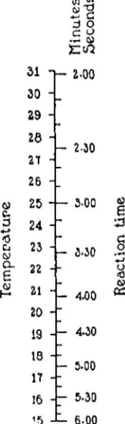
FIG. 191. Scale indicating reaction period required for complete decomposition of α-amino acids, and 0.07 decomposition of urea, when total volume of reacting solution is 8 ml. (Van Slyke).
allowed to stand thusly until within one minute of the end of the reaction time given on the accompanying scale (Fig. 1 9 1 ) . During this period if the mercury level is forced down below the 50-ml. mark by the pressure of the evolved gases, the stopcock, a, is opened momentarily to bring the mercury level back to the above mark. During the last minute of the reaction time, the mixture is shaken to complete the evolution of nitrogen and, to keep the mercury level from dropping, the stopcock, a, is occasionally opened as above.
TRANSFER OF THE NITROGEN AND NITRIC OXIDE MIXTURE TO THE HEMPEL PIPETTE AND THE
ABSORPTION OF THE NITRIC OXIDE
The leveling bulb, L, is placed in the upper ring and the stopcock, a (Fig.
1 8 7 ) , is opened. A few milliliters of water are placed in the cup, E, above the small pool of mercury and the rubber-tipped capillary of the Hempel pipette is held firmly with the left hand against the bottom of the cup, E. The stop
cock on the Hempel pipette is turned so as to connect the rubber-tipped delivery capillary with the bulbs, as shown in Fig. 192. The stopcock, b, is opened so as to force the mixture of gases slowly over into the Hempel pipette. The aqueous solution will continue to evolve gas ( N O ) as long as it remains in the chamber but no attempt should be made to collect this.
Consequently, the transfer should be stopped as soon as a trace of the liquid has passed the bore of the stopcock on the Hempel pipette. The stopcock, b, is closed and so is the stopcock on the Hempel pipette, the latter being turned counterclockwise but not far enough to connect the permanganate-filled cup with the bulbs. Then the Hempel pipette is gently shaken for a few seconds with a swirling horizontal motion, being careful not to entrap air in the exposed bulb. The stopcock on the Hempel pipette is turned quickly to admit a small amount of the permanganate from the cup into the bulb, forcing the gas and solution in the capillary between these parts into the bulb.
Then the stopcock on the Hempel pipette is quickly closed to avoid loss of gas through it. The pipette is shaken gently again horizontally and then set aside while the chamber, C, is being washed. Since nitric oxide continues to form in the chamber, C, this must be thoroughly cleaned before the next operation. The stopcock, b, is opened and the aqueous solution which is forced up into the cup, E, is removed by insertion of the suction tube (see description under Manometric Carbon Determination). The stopcock, b, is closed and the leveling bulb, L, is placed in the lower ring. Water is ad
mitted through the cup, E, and the stopcock, b, until the chamber, C, is full.
The stopcock, b, is closed, the leveling bulb, L, is placed in the upper ring, the stopcock, b, is opened and the water which is forced out into the cup, E,
is again removed by suction. The washing is done three times just as in the case of the carbon determination.
< Hg L E V E L I N G BULB, L , OF MANOMETRIC APPARATUS
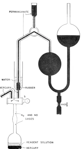
FIG. 192. Hempel pipette—ready for transfer of nitrogen and nitric oxide from extraction chamber. Permanganate in capillaries of Hempel pipette, cup, and bulbs.
RETURN OF PURIFIED NITROGEN TO THE MANOMETRIC APPARATUS
The leveling bulb, L, is in the upper ring and mercury fills the chamber, C, the stopcock, b, and a few milliliters of it is in the cup, E, following the washings. Then the leveling bulb, L, is placed in the lower ring. Ten milliliters of distilled water, in two 5-ml. portions from the cup, E, is admitted to the extraction chamber. A mercury seal is made and the chamber evacuated draw-
ing the mercury level down to the 50-ml. mark, in the usual manner already described several times in this chapter. The evacuated chamber is shaken for one minute to remove the greater part of the air from the water. Then the leveling bulb, L, is placed in the upper ring, the stopcock, a, opened and the extracted air ejected through the stopcock, b. Then one milliliter of the air-free water is forced up into the cup, E, and the stopcock, b, closed. The
< Hg LEVELING B U L B , L , OF MANOMETRIC APPARATUS
FIG. 193. Hempel pipette—containing purified nitrogen, with cup and one capillary rilled with air-free water.
stopcock on the Hempel pipette is turned quickly counterclockwise to connect the cup above it with the delivery capillary and the alkaline permanganate present in the cup is allowed to drain off. T h e stopcock is left in this posi
tion and the cup and capillary thoroughly washed with distilled water and allowed to drain. The Hempel pipette is held in the left hand and the rubber- tipped delivery capillary is pressed against the bottom of the cup, E. The stopcock, b, is opened and air-free water from the extraction chamber is forced up to fill the empty delivery capillary of the Hempel pipette and about one ml.
passed into the cup above its stopcock, as shown in Fig. 193. The stopcock, b,
is closed and the stopcock on the Hempel pipette turned clockwise to admit a little air-free water to wash the capillary, between this stopcock and the bulb, free from permanganate. This stopcock is turned again clockwise to connect the Hempel bulb with the delivery capillary as shown in Fig. 194.
The leveling bulb, L, is placed in the lower ring and the stopcock, b, is opened to admit the nitrogen from the Hempel pipette to the extraction
Hg L E V E L I N G B U L B , L , OF MANOMETRIC APPARATUS
FIG. 194. Hempel pipette—after return of purified nitrogen to extraction chamber.
Small quantity of nitrogen in capillary has not yet been drawn into extraction chamber.
chamber. The stopcock, b, is closed to stop the transfer when the column of permanganate following the gas has entered the capillary above the stopcock, b, as shown in Fig. 194. The stopcock on the Hempel pipette is closed and the pipette removed to its stand. The cup, E, above the extraction chamber is washed with several portions of water, to remove as much permanganate as possible. About one ml. of mercury is placed in the cup, E, and the stop
cock, b, opened and closed quickly to admit mercury to force the trapped nitrogen and permanganate from the capillary into the extraction chamber and to make a mercury seal.
MEASURING THE NITROGEN
The leveling bulb, L, is placed below the table top and the level of the water in the chamber lowered until the water meniscus is at either the 0.5 ml.
or the 2.0-ml. mark, depending upon the amount of nitrogen present. ( I f this exerts less than 100 mm. of pressure at the 2-ml. mark, it is preferable to read the pressure when the gas volume is 0.5 ml.) The meniscus is brought exactly to the desired volume by manipulation of the stopcock, a (Fig. 1 8 7 ) , making use of a reading lens. With the aid of the illuminated background for the manometer and a reading lens, the manometer reading, px, is recorded.
The leveling bulb, L, is placed in the upper ring, the stopcocks, a, and then, b, opened (in this order), and the gas ejected. The stopcock, b, is closed, the leveling bulb, L, lowered below the table top (mercury seal) and the level of the water in the chamber again brought down until the water meniscus is at either the 0.5- or 2.0-ml. mark, at whichever it was for the pi reading, and the stopcock, a, closed. Then the manometer reading, p0, is recorded.
BLANK ANALYSIS
Just as was the case with the manometric carbon determination, a blank analysis must be done as a control of the reagents. The exact procedure described above for the determination of α-amino nitrogen must be repeated, substituting 5 ml. of water for the 5 ml. of amine solution. Obviously, the blank analysis must be done at the same volume as was the sample. For a few weeks after the preparation of new sodium nitrite solution the correction continues to change slightly (diminishes), eventually becomes constant, and then need be determined only occasionally. When the analysis yields enough nitrogen to give a pressure of more than 100 mm. at a volume of 2.0 ml., variations in the correction with ordinary changes in room temperature may be neglected. However, if the gas measurements must be made at a volume of 0.5 ml., the correction should be determined at a temperature almost the same as that of the analysis. Corrections usually are equal to about 5 - 7 mm.
with the gas at a volume of 2.0 ml. and about 2 0 - 3 0 mm. at 0.5 ml.
Calculation:
The pressure exerted by the a-amino nitrogen is calculated from the equation:
PN2 = P i — Po — c
where c = p1 — p0 obtained in the blank analysis.
The weight of α-amino nitrogen is equal to the pressure multiplied by the factor shown in Table 31, that is,
mg. of α-amino Ν = PN X factor