1
In: Biosensors and Bioelectronics 106: pp. 86-92. (2018) https://doi.org/10.1016/j.bios.2018.01.060 Manuscript as accepted This work is licensed under the Creative Commons Attribution-NonCommercial-
NoDerivatives 4.0 International License (CC BY-NC-ND 4.0).
A silicon-based neural probe with densely-packed low-impedance titanium nitride microelectrodes for ultrahigh-resolution in vivo recordings
Richárd Fiátha,b, Bogdan Cristian Raducanuc,d, Silke Musac, Alexandru Andreic, Carolina Mora Lopezc, Chris van Hoofc,d, Patrick Ruthere,f, Arno Aartsg, Domonkos Horvátha,b, István
Ulberta,b
a Institute of Cognitive Neuroscience and Psychology, Research Centre for Natural Sciences, Hungarian Academy of Sciences, Magyar tudósok körútja 2, H-1117 Budapest, Hungary
b Faculty of Information Technology and Bionics, Pázmány Péter Catholic University, Práter utca 50/A, H-1083 Budapest, Hungary
c Interuniversity Microelectronics Center (IMEC), Kapeldreef 75, B-3001 Heverlee, Belgium
d Electrical Engineering Department (ESAT), KU Leuven, Kasteelpark Arenberg 10, B-3001 Leuven, Belgium
e Microsystem Materials Laboratory, Department of Microsystems Engineering (IMTEK), University of Freiburg, Georges-Koehler-Allee 103, D-79110 Freiburg, Germany
f BrainLinks-BrainTools Cluster of Excellence at the University of Freiburg, Georges-Koehler- Allee 80, D-79110 Freiburg, Germany
g ATLAS Neuroengineering, Kapeldreef 75, B-3000 Leuven, Belgium
Correspondence:
Richárd Fiáth
email: fiath.richard@ttk.mta.hu
2 Abstract
In this study, we developed and validated a single-shank silicon-based neural probe with 128 closely-packed microelectrodes suitable for high-resolution extracellular recordings. The 8- mm-long, 100-µm-wide and 50-µm-thick implantable shank of the probe fabricated using a 0.13-µm complementary metal-oxide-semiconductor (CMOS) metallization technology contains square-shaped (20 × 20 µm2), low-impedance (~50 kΩ at 1 kHz) recording sites made of rough and porous titanium nitride which are arranged in a 32 × 4 dense array with an inter- electrode pitch of 22.5 µm. The electrophysiological performance of the probe was tested in in vivo experiments by implanting it acutely into neocortical areas of anesthetized animals (rats, mice and cats). We recorded local field potentials, single- and multi-unit activity with superior quality from all layers of the neocortex of the three animal models, even after reusing the probe in multiple (> 10) experiments. The low-impedance electrodes monitored spiking activity with high signal-to-noise ratio; the peak-to-peak amplitude of extracellularly recorded action potentials of well-separable neurons ranged from 0.1 mV up to 1.1 mV. The high spatial sampling of neuronal activity made it possible to detect action potentials of the same neuron on multiple, adjacent recording sites, allowing a more reliable single unit isolation and the investigation of the spatiotemporal dynamics of extracellular action potential waveforms in greater detail. Moreover, the probe was developed with the specific goal to use it as a tool for the validation of electrophysiological data recorded with high-channel-count, high-density neural probes comprising integrated CMOS circuitry.
3 Keywords
action potential waveform; CMOS metallization technology; high-density neural recording;
multi-unit activity; neocortex, single-unit activity
4 1. INTRODUCTION
Electrodes developed to record electrical activity from the extracellular space of the brain tissue in vivo have a long history spanning several decades (Wise et al. 1970; Wise et al. 2008). First devices were insulated microwires and tetrode configurations thereof (McNaughton et al. 1983;
Okeefe and Recce 1993; Wilson and McNaughton 1993) comprising a single recording site and four individual sites, respectively, as well as silicon-based probes with a limited number of recording sites related to the applied fabrication process (Wise et al. 1970; Herwik et al. 2009).
Despite the excellent temporal resolution of electrophysiological recordings, first devices usually lacked the necessary spatial resolution at the neuronal level. Although higher spatial coverage could be achieved by increasing the density and number of electrodes (Norlin et al.
2002; Du et al. 2011; Berenyi et al. 2014; Shobe et al. 2015; Scholvin et al. 2016; Barz et al.
2017), these properties are primarily limited by the maximum number of interconnect metallization leads located in the probe shank, which in turn is limited by the width of the shank (Du et al. 2011). Since wider shanks induce more tissue stress, which might result in the degradation of the quality of the recorded neural signals, increasing of the shank width is not an optimal solution to achieve higher spatial resolution. However, the use of complementary metal-oxide-semiconductor (CMOS) technology allows to circumvent this limitation by reducing the size of interconnect wires and/or by integrating active circuitry on the probe for multiplexing neural signals or for the selection of a subset of recordings sites (Seidl et al. 2011;
Torfs et al. 2011; Seidl et al. 2012; Lopez et al. 2014; Ruther and Paul 2015; Rios et al. 2016;
Lopez et al. 2017; Raducanu et al. 2017).
Neuronal signals monitored using probes with high-density electrodes undoubtedly show the advantages of high-spatial sampling under in vivo conditions (Blanche et al. 2005; Gold et al.
2006; Delgado Ruz and Schultz 2014; Neto et al. 2016). For instance, neural data recorded with a dense electrode array might significantly improve the accuracy of spike sorting methods and
5
the reliability of single unit isolation, which in turn may increase the unit yield remarkably (McNaughton et al. 1983; Gray et al. 1995; Harris et al. 2000; Blanche et al. 2005). However, the complexity of state-of-the-art CMOS-based probes comprising active circuit components (Lopez et al. 2017; Raducanu et al. 2017) and the huge amount of neural data provided by them makes the validation of their recording performance difficult. Therefore, passive silicon-based probes with a relatively low number (~100) of densely-packed microelectrodes and with physical attributes (e.g. shaft dimensions) similar to active CMOS probes might be valuable tools to verify the recording capabilities of the latter devices (Lopez et al. 2017; Raducanu et al. 2017) by directly comparing neural signals obtained with both probe types.
This paper presents the fabrication and in vivo validation of a silicon-based planar probe comprising a dense array of closely-spaced low-impedance electrodes arranged in a 32 × 4 grid.
Recording capability and durability of the device fabricated using a CMOS technology were assessed in acute experiments by recording and evaluating the cortical activity of anesthetized rats, mice and cats. Wideband electrical activity was examined by calculating the single unit yield, the peak-to-peak amplitude and duration of action potentials (APs) of isolated neuron clusters and the signal-to-noise ratio of the acquired neural signal. Moreover, the implantable shaft and the microelectrode array was designed similarly to a recently developed CMOS-based probe comprising active electronic components on its shaft and base (Raducanu et al. 2017). In the near future, this will allow for the direct comparison of neural data recorded with both types of devices.
6 2. MATERIALS AND METHODS
2.1 Probe layout
Figure 1 schematically illustrates the Michigan-style probe developed and tested in this study. It comprises a slender probe shaft carrying an array of 32 × 4 titanium nitride electrodes:
127 square recording sites and a single reference electrode with a rectangular shape. The electrodes are interfaced via metal lines to a respective number of contact pads integrated on the probe base. The corresponding probe shaft cross-section indicating electrode leads and the metallization in contact with neural tissue is given in Figure S1 (VII). The probe is interconnected to external instrumentation using wire bonding to a printed circuit board (PCB).
Figure 1. –Schematic illustration of the developed probe.
2.2 Probe fabrication
The fabrication procedure described in the Supplementary material is done using a commercial 0.13-µm CMOS process, with a three-metal-layer (AlCu) back-end-of-line (BEOL) on 200- mm-diameter silicon wafers (Figure S1). Metal features down to 0.13-µm can be fabricated in this process, which is beneficial for creating high-density neural probes with densely-packed recording sites and interconnecting lines.
7 2.3 Electrical impedance spectroscopy
The magnitude and phase angle of the electrical impedance of titanium nitride electrodes was measured in vitro to investigate the impedance variability of recording sites and the reusability of the probes by examining the change of the impedance over time. The details of impedance measurement are described in the Supplementary material.
2.4 In vivo electrophysiological recordings
The fabricated silicon probes were validated in the brain tissue of three animal species, namely, rats, mice and cats. All experiments were performed according to the EC Council Directive of November 24, 1986 (86/89/EEC), and all procedures were reviewed and approved by the local ethical committee and the National Food Chain Safety Office of Hungary (license number:
PEI/001/2290-11/2015). Experimental procedures are detailed in the Supplementary material.
2.5 Histology
To verify the recording location of the probe, we processed the brain tissue of animals. Details of histological procedures are described in the Supplementary material.
2.6 Spike sorting
To assign the recorded action potentials to individual neurons, automatic spike sorting was performed using a software developed in MATLAB (Kilosort; Pachitariu et al. 2016). Manual revision of the neuron clusters found by Kilosort was done in Phy, an open source neurophysiological data analysis package written in Python (https://github.com/kwikteam/phy). Details of spike sorting are described in the Supplementary material.
8 2.7 Calculation of the signal-to-noise ratio
The signal-to-noise ratio (SNR) was calculated with a method described previously (Seidl et al.
2010). Details of the calculation can be found in the Supplementary material.
9 3. RESULTS AND DISCUSSION
3.1 Probe design and packaging
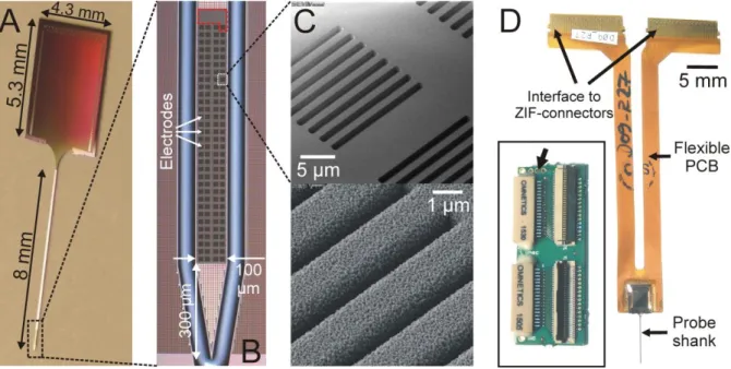
The silicon probe demonstrated in this study was developed using a 0.13-µm CMOS metallization technology (Figure S1). Figure 2 shows optical and scanning electron micrographs of the fabricated probe, the titanium nitride (TiN) electrodes and the probe packaging. The neural probe consists of an 8-mm-long, 100 µm wide, 50 µm thick implantable shank, and a base (4.3 × 5.3 mm2) containing contact pads to interface with the electrophysiological recording system (Figure 2A). The tapered neck of the silicon shank is 975 µm long and is 1600 µm wide at the probe base (Figure 2A). The 128 TiN microelectrodes located at the tip region of the shank form a two-dimensional high-density array comprising 32 rows and 4 columns (Figure 2B). The square-shaped recording sites with 20 µm side length are placed with an inter-electrode pitch of 22.5 µm, and contain multiple rectangular vias (14 × 1 µm2) to increase their effective recording surface, thus reducing their electrical impedance (Figure 2C). One electrode located at the top row of recording sites has an approximately ten times larger area (87.5 × 42.5 µm2 + 20 × 20 µm2) and serves as an internal reference electrode (Figure 2B). Furthermore, the probe has a chisel-shaped tip with a 300-µm-long tapered section which contains no recording sites (Figure 2B).
The silicon probes were wire-bonded onto a double-wing flexible PCB which comprises two interface sections for zero insertion force (ZIF) connectors, each with 64 metal contacts (Figure 2D). The area around the probe base and the bond wires was sealed with epoxy resin to protect the interconnections from contact with fluids. The flexible PCB is about 55 mm long and 8.7 mm wide at the probe base. The assembled probe weighs 0.18 grams and can be connected to the headstages of the electrophysiological recording system using ZIF-to-Omnetics adapter PCBs (Figure 2D, inset). On the adapter PCB, solder pads are available for the selection of the required reference type (internal/external) for neural recordings (Figure 2D, inset).
10
Figure 2. – The fabricated 128-channel silicon-based neural probe. (A) Optical micrograph of
a singulated final probe. (B) Close-up view of the shank tip containing the TiN electrodes. The large internal reference electrode is located at the top row of electrodes (red dashed polygon).
(C) Scanning electron micrograph images of the electrode via openings before (top) and after (bottom) deposition of TiN. (D) Optical micrograph of the silicon probe after wire-bonding and packaging. ZIF (zero insertion force)-to-Omnetics adaptor boards were used (inset) to connect the flexible printed circuit board (PCB) with the amplifiers of the recording system. Solder pads for the selection of the type of the reference (internal/external) are indicated by a black arrow.
3.2 Electrical impedance measurement results
The SNR of neural recordings can be improved by reducing the thermal noise provided by lowered electrical impedance (Baranauskas et al. 2011; Boehler et al. 2015; Chung et al. 2015).
TiN was chosen as the electrode material because of the back-end-of-line compatibility with CMOS fabrication processes (Musa 2016). Furthermore, TiN is biocompatible as well as chemically stable in biological tissue over the long term (Schaldach and Bolz 1992). Multiple
11
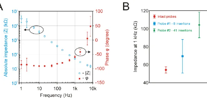
narrow trenches were made at each recording site during probe fabrication, then rough and porous TiN was deposited on this grid-like structure (Figure 2C). The porous nature of TiN coupled with trench sidewall deposition increased the effective surface area of recording sites and thus significantly reduced their impedance. The Bode plot of the impedance magnitude and phase of electrodes of four probes measured in vitro is shown in Figure 3A. The average impedance magnitude and phase at 1 kHz for n = 508 recording sites were 49.28 ± 3.29 kΩ and -59.12 ± 5.35°, respectively.
The durability of the silicon probes was assessed by examining the change of the electrical impedance and the recording capability of electrodes after reusing the devices multiple times.
Repeated in vivo insertions of two probes into the brain tissue of animals showed only a modest increase of electrode impedance measured at 1 kHz (Figure 3B). Furthermore, only two faulty recording sites with an impedance magnitude higher than 10 MΩ were found after the intensive experimental usage (both electrodes were found on Probe #1). Therefore, we can conclude that the majority of low-impedance TiN electrodes of the probe can withstand several dozens of brain insertions and over 50 hours of recording in brain tissue (16 acute experiments with the probe implanted in the brain for ~3 hours during each experiment) without considerable deterioration in their recording performance or impedance increase.
12
Figure 3. – Results of the electrical impedance measurements. (A) Mean and standard deviation (SD) of the impedance magnitude (blue) and phase (red) of TiN electrodes (n = 508 recording sites of four probes) measured at thirteen different frequencies (1 Hz – 7500 Hz) before in vivo use. The impedance values of internal reference electrodes were excluded from the calculations. (B) Mean and SD of the impedance at 1 kHz of TiN electrodes of four intact probes (red) and of two probes used in multiple acute experiments (Probe #1: a total of 8 insertions in 8 rat experiments, blue; Probe#2: a total of 41 insertions in 8 rat and 8 mouse experiments, green). For Probe#1, two faulty electrodes with high (> 10 MΩ) impedance values were discarded from the calculations.
3.3 General recording characteristics
The silicon probes were acutely implanted into the brain tissue of anesthetized mice, rats and cats. Having the dura mater removed properly above the implantation site, only a slight dimpling of the brain tissue (< 300 µm of tissue displacement) was observed during probe insertion, usually without damaging blood vessels located on the cortical surface. After probe insertion, local field potentials (LFPs; activity of large neuron populations; frequency band:
0.1–500 Hz), multi-unit and single-unit activity (MUA and SUA, respectively; action potentials originating from neurons in close proximity to microelectrodes; frequency band: 500–5000 Hz)
13
were recorded with excellent quality from the neocortex of animals (see examples of rat data in Figure 4A and B). All electrodes of the tested probes were found to be functional after the first insertion.
With the combination of ketamine and xylazine, the chemical agents used in this study to induce anesthesia, a brain rhythm with a characteristic peak frequency of about 1 Hz can be recorded in the neocortex (Crunelli and Hughes 2010). During this brain oscillation, called slow wave activity (SWA), the rhythmic alternation of two phases, both with a duration of a few hundred milliseconds, can be observed in the neocortex of the investigated species: up-states with high synaptic and spiking activity and down-states with ceased AP firing of neurons (Steriade et al.
1993; Chauvette et al. 2011; Crunelli et al. 2012; Fiath et al. 2016). We used certain well- described features of the SWA as benchmarks to verify the recorded brain signals. The rhythmic changes in the polarity of the wideband cortical potentials obtained from the anesthetized animals were amongst the most prominent signs of the ketamine/xylazine-induced SWA (e.g.
for rats see Figure 4A and B). Furthermore, the observed features of up- and down-states (e.g.
frequency of occurrence and duration, polarity of the LFP in different cortical layers, distribution of the unit activity across layers during up-states) were in accordance with literature data. For example, the LFP recorded in infragranular cortical layers (layer 5 and 6) of rats and cats showed positive half-waves during down-states, while the polarity of half-waves corresponding to up-states was negative (Figure 4A and B; Chauvette et al. 2010; Fiath et al.
2016). The electrodes of the probe cover an effective recording area of 717.5 × 87.5 µm2 allowing to record from multiple (2-4) cortical layers simultaneously. Based on previous experiments conducted in rats (Sakata and Harris 2009; Fiath et al. 2016), the spiking activity during up-states was found the strongest in cortical layer 5 (e.g. Figure 4B, bottom half of the MUA depth profile), while sparse firing was typical in supragranular layers (e.g. Figure 4B, top third of the MUA depth profile which corresponds to the bottom of layer 3). The approximate
14
recording location of the probe in the brain tissue as well as the borders of cortical layers were determined by post-mortem histological examinations (Figure 4C). Although this study focused on cortical recordings, it is important to note that the length of the shank (8 mm) allows to record neuronal activity of rodents from brain structures located deeper as well (e.g. from the thalamus or the hippocampus).
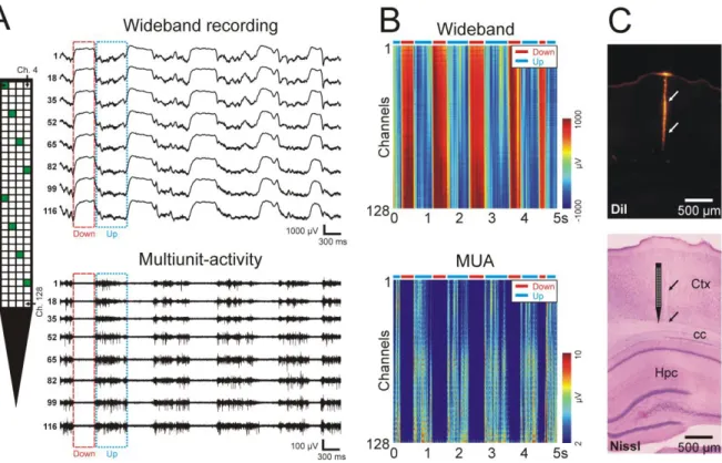
Figure 4. – Electrophysiological recording capabilities of the neural probe. (A) Representative
5-sec-long wideband and multiunit-activity traces recorded by eight electrodes (indicated by green squares on the probe schematic) from deep layers of the somatosensory cortex of an anesthetized rat. Sample up-states (“Up”) and down-states (“Down”), are marked with dotted blue and dashed red boxes, respectively. The electrode-channel relationship is indicated on the probe schematic (ch - channel). (B) Color-coded visualization of the cortical activity recorded on 128 channels simultaneously. The colored depth profiles were constructed from the same 5- sec long segment of cortical recording as shown in panel A. Up- and down-states are indicated by blue and red horizontal bars, respectively, located above the color maps. The MUA depth profile was constructed by filtering the wideband traces with a software filter (3rd-order
15
Butterworth filter, 500-5000 Hz bandpass, zero-phase shift), then taking the absolute value of the filtered data and applying an additional 100-Hz low-pass filter. (C) Coronal rat brain section showing the track of the silicon probe (indicated by arrows) located in the neocortex.
The micrographs were taken under a fluorescent microscope before Nissl-staining (top) and after staining (bottom). The schematic tip region of the probe is illustrated on the bottom image next to the probe track. Ctx – neocortex; cc – corpus callosum; Hpc – hippocampus.
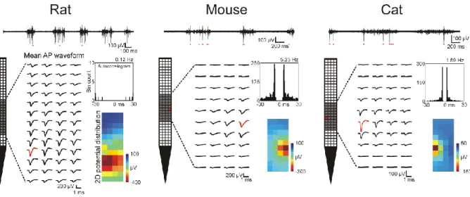
Action potentials corresponding to individual neurons were extracted using spike sorting. A large number of single units could be isolated from the cortical data recorded in rats (n = 533 units), mice (n = 480) and cats (n = 155). Examples of the AP waveforms and autocorrelograms of well-separated cortical units recorded from each species are demonstrated in Figure 5. In general, the activity of more than a dozen well-separated neurons firing high-amplitude APs could be isolated from the data acquired at a single recording position (mean ± SD, 14.16 ± 8.68 single units, range: 5 – 54). The mean peak-to-peak amplitude of the APs of sorted units was usually over 100 µV, including neurons firing APs with amplitudes over 1 mV (rats, mean
± SD, 292.84 ± 162.79 µV, range: 44.45 – 1112.92 µV; mice, 212.02 ± 108.42 µV, range: 47.35 – 773.31 µV; cats, 138.25 ± 78.38 µV, range: 49.95 – 504.57 µV). The measured amplitudes are comparable to AP amplitudes recorded with similar high-density silicon probes (Blanche et al. 2005; Scholvin et al. 2016).
16
Figure 5. – Representative high-resolution mean action potential (AP) waveforms of cortical
neurons obtained with the silicon probe in three animal models. APs of the single units could be recorded on multiple, adjacent electrodes. The gray shaded area on the probe schematic shows the region of electrodes where the mean AP waveforms of the particular unit were calculated. The red AP waveform and red square on the probe schematic indicate the recording site which recorded the APs of the neuron with the largest peak-to-peak amplitude. The autocorrelogram (bin size: 1 ms) and the firing rate of the units are shown to the right of the AP waveforms, together with the two-dimensional potential distribution calculated at the time point corresponding to the negative peak of the mean AP waveforms. At the top of the figure, 3-sec-long multiunit-activity traces are shown containing multiple APs of the demonstrated single units (APs indicated by red asterisks). Traces were recorded by the electrode colored red on the probe schematic.
To further assess the recording quality, we calculated the SNR on all channels of a 30-sec-long interval of a typical cortical recording. The mean SNR of the recording obtained from deep cortical layers was found to be 9.83 ± 2.27 dB with a range of 5.85 – 15.76 dB, which suggests that single unit activity was recorded on the majority of the recording channels. Furthermore, the level of the root mean square (RMS) noise of the electrophysiological recording system was
17
estimated in physiological saline solution, in vitro (3.77 ± 0.33 µVrms, f = 0.1 – 7500 Hz, no Faraday cage used, the input-referred noise of the amplifier was ~2.4 µVrms). Low noise levels could also be achieved during in vivo recordings by a proper grounding of the recording system (without the use of a Faraday cage).
Neuronal activity recorded from the neocortex was stable over longer time periods (usually for hours). For example, we have been able to monitor the APs of the same neurons on the same recording channels for several hours (3 h) without considerable change in their AP waveform shape or amplitude. To quantify the recording stability, the peak-to-peak amplitude of the AP waveform of a subset of single units from a rat recording (n = 3 well-separated units with AP peak-to-peak amplitudes over 500 µV) was measured at the start of the recording session (first 5 minutes). Next, we determined the highest (or lowest) peak-to-peak AP amplitude value of these units which was recorded on the same channel during the three hours. Finally, we calculated the absolute difference of the two values. On average, a 22.66 ± 9.94 % difference was found between the peak-to-peak amplitudes. Usually, the amplitude change of APs was the most intense during a short period (~15-30 min) immediately after probe insertion during which the brain tissue recovered from the insertion trauma. During this time period, a noticeable electrode drift might be present, with the recorded AP waveforms of some of the neurons shifting 1-2 rows of electrodes upwards corresponding to a distance of 20-50 µm, presumably due to the slow displacement of the cortical tissue in the direction of the pial surface.
3.4 Neural action potentials recorded with high spatial resolution
APs of individual neurons were detected by multiple, adjacent recording sites of the probe (Figure 5). The number of recording sites containing the APs of the same neuron was highly variable across units and presumably depends on the type of neuron and the distance between the electrodes and the cell. AP waveforms of cortical single units were frequently observed on more than 30 channels, while the APs of certain cells were detected only on a few, neighboring
18
channels (number of channels recording the AP of the neuron with a peak-to-peak amplitude over 50 µV: rats, mean ± SD, 28.42 ± 17.37, range: 1 – 101; mice, 11.72 ± 7.78, range: 1 – 58;
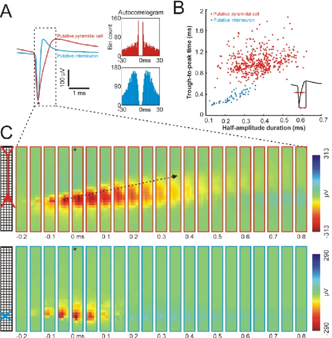
cats, 13.32 ± 9.96, range: 1 – 46). Furthermore, Bartho et al. (2004) showed that cortical pyramidal cells and interneurons might be distinguished based on the duration of their AP waveforms, namely, narrow APs correspond to interneurons while most pyramidal cells fire wide APs (Bartho et al. 2004). In this study, using the 128-channel high-density silicon probe, we could replicate the findings of Bartho et al. (2004). As demonstrated in panel A and B of Figure 6, the visualization of the duration of APs of putative interneurons and pyramidal cells recorded from the rat neocortex results in two distinct clusters. Similar results were extracted from the mouse and cat data displaying two groups corresponding to narrow and wide APs (data not shown).
Besides the high temporal resolution, probes with high-density electrodes also provide high spatial resolution which might be exploited to identify different types of neurons. Pyramidal cells, for instance, usually have a larger cell body and a larger spatial expanse of dendrites compared to interneurons. Therefore, the AP waveform of the former is expected to be recorded by a higher number of electrodes simultaneously (Figure 6C). Furthermore, other features of high-resolution APs might be used to determine the class of neurons. For example, the backpropagation of the APs from the cell body of the neuron into the dendritic shaft was observed in case of putative pyramidal cells but was not apparent in case of putative interneurons (Figure 6C; Buzsaki and Kandel 1998). In conclusion, electrophysiology-based classification of neurons based on their electrical footprints obtained with high-density probes might be a useful method to investigate the role of different neuron types in the cortical microcircuitry.
19
Figure 6. – Spatiotemporal properties of recorded action potentials (APs) of neocortical
neurons. (A) Mean AP waveform of a putative neocortical pyramidal cell (red) and a putative interneuron (blue) with their corresponding autocorrelogram (bin size: 1 ms) on the right. (B) The half-amplitude duration and the trough-to-peak time calculated from the mean AP waveform (inset) of all single units isolated from the rat recordings. (C) Color maps constructed from the mean AP waveform of a putative pyramidal cell (top) and a putative interneuron (bottom) by plotting the potential values at each electrode and at each sample point located within the dashed box in panel A (each map corresponds to one sample point). Time point zero corresponds to the negative peak of the AP (indicated by an asterisk in panel A and C). Note
20
the longer duration of the AP of the pyramidal cell and the propagation of the AP in the direction of the apical dendritic region of the neuron (black arrow). The approximate position of the soma of the two neurons is indicated on the probe schematic.
21 4. CONCLUSIONS
In this study, we demonstrated the fabrication process and the recording capabilities of a 128- channel high-density silicon-based microelectrode array comprising low-impedance, closely- packed titanium nitride electrodes. The high-quality and stable neural recordings provided by the tested device allowed us to monitor the simultaneous activity of more than a dozen single units in the neocortex of anesthetized mammals. Spikes of the same neuron could be recorded with numerous, adjacent recording sites, allowing the spatial mapping of AP generation and propagation, in vivo. Furthermore, the silicon probes were found to be highly durable, that is, they could be used in multiple experiments incorporating tens of hours of recording without a major impairment in their recording performance.
Although high-quality recordings were obtained with the developed silicon probe, a few limitations of the device are important to note. First, the chisel-shaped tip may make a smooth penetration of the probe into the brain tissue challenging, especially if the dura mater is left intact. However, instead of the chisel-shaped design, it is possible to realize a pointy tip for the probe shaft, which enables to pierce through the dura and reduces the dimpling effect during implantation (Barz et al. 2017). Second, the brain area monitored by the probe is limited to only a few hundred micrometers along the dorsoventral axis (effective recording area: 717.5 × 87.5 µm2), which in most cases is sufficient to record AP waveforms of several neurons at the same time, but it does not allow the experimenter to record the activity from all cortical layers and/or from multiple brain regions simultaneously. Third, the current design of the probe is suitable only for use in acute experiments, however, the flexible PCB might be miniaturized to allow chronic implantations as well.
Moreover, recent technological progress made it possible to develop high-channel-count, high- density silicon-based probes with integrated CMOS circuitry (Lopez et al. 2017; Raducanu et al. 2017). The microelectrode array realized in this study will be applied to validate the
22
electrophysiological recording performance of such full CMOS-based probes comprising recording sites with similar dimensions and layout.
23 Acknowledgements
The research leading to these results has received funding from the European Union’s Seventh Framework Programme (FP7/2007–2013) under grant agreement no. 600925 (NeuroSeeker) and from Hungarian Brain Research Program Grants (Grant Nos. KTIA_13_NAP-A-I/1 and KTIA-13-NAP-A-IV/1-4,6). The research within project No. VEKOP-2.3.2-16-2017-00013 by I. Ulbert and D. Horváth was supported by the European Union and the State of Hungary, co- financed by the European Regional Development Fund. R. Fiáth is thankful to the Hungarian National Research, Development and Innovation Office (postdoctoral excellence programme, PD_17 No. 124175).
Disclosure
The authors declare no conflict of interests. Arno Aarts and Patrick Ruther are co-founders of ATLAS Neuroengineering.
24 References
Baranauskas, G., Maggiolini, E., Castagnola, E., Ansaldo, A., Mazzoni, A., Angotzi, G.N., Vato, A., Ricci, D., Panzeri, S., Fadiga, L., 2011. J. Neural Eng. 8, 066013.
Bartho, P., Hirase, H., Monconduit, L., Zugaro, M., Harris, K.D., Buzsaki, G., 2004. J.
Neurophysiol. 92, 600-608.
Barz, F., Livi, A., Lanzilotto, M., Maranesi, M., Bonini, L., Paul, O., Ruther, P., 2017. J.
Neural Eng. 14, 036010.
Berenyi, A., Somogyvari, Z., Nagy, A.J., Roux, L., Long, J.D., Fujisawa, S., Stark, E., Leonardo, A., Harris, T.D., Buzsaki, G., 2014. J. Neurophysiol. 111, 1132-1149.
Blanche, T.J., Spacek, M.A., Hetke, J.F., Swindale, N.V., 2005. J. Neurophysiol. 93, 2987- 3000.
Boehler, C., Stieglitz, T., Asplund, M., 2015. Biomaterials 67, 346-353.
Buzsaki, G., Kandel, A., 1998. J. Neurophysiol. 79, 1587-1591.
Chauvette, S., Crochet, S., Volgushev, M., Timofeev, I., 2011. J. Neurosci. 31, 14998-15008.
Chauvette, S., Volgushev, M., Timofeev, I., 2010. Cereb. Cortex 20, 2660-2674.
Chung, T., Wang, J.Q., Wang, J., Cao, B., Li, Y., Pang, S.W., 2015. J. Neural Eng. 12, 056018.
Crunelli, V., Hughes, S.W., 2010. Nat. Neurosci. 13, 9-17.
Crunelli, V., Lorincz, M.L., Errington, A.C., Hughes, S.W., 2012. Pflugers Arch. 463, 73-88.
Delgado Ruz, I., Schultz, S.R., 2014. J. Neurosci. Methods 233C, 115-128.
Du, J., Blanche, T.J., Harrison, R.R., Lester, H.A., Masmanidis, S.C., 2011. PLoS One 6, e26204.
Fiath, R., Kerekes, B.P., Wittner, L., Toth, K., Beregszaszi, P., Horvath, D., Ulbert, I., 2016.
Eur. J. Neurosci. 44, 1935-1951.
Gold, C., Henze, D.A., Koch, C., Buzsaki, G., 2006. J. Neurophysiol. 95, 3113-3128.
25
Gray, C.M., Maldonado, P.E., Wilson, M., McNaughton, B., 1995. J. Neurosci. Methods 63, 43-54.
Harris, K.D., Henze, D.A., Csicsvari, J., Hirase, H., Buzsaki, G., 2000. J. Neurophysiol. 84, 401-414.
Herwik, S., Kisban, S., Aarts, A.A.A., Seidl, K., Girardeau, G., Benchenane, K., Zugaro, M.B., Wiener, S.I., Paul, O., Neves, H.P., Ruther, P., 2009. J Micromech. Microeng. 19, 074008.
Lopez, C.M., Andrei, A., Mitra, S., Welkenhuysen, M., Eberle, W., Bartic, C., Puers, R., Yazicioglu, R.F., Gielen, G.G.E., 2014. IEEE J. Solid-St. Circ. 49, 248-261.
McNaughton, B.L., Okeefe, J., Barnes, C.A., 1983. J. Neurosci. Methods 8, 391-397.
Lopez, C.M., Putzeys, J., Raducanu, B.C., Ballini, M., Wang, S., Andrei, A., Rochus, V., Vandebriel, R., Severi, S., Van Hoof, C., Musa, S., Van Helleputte, N., Yazicioglu, R.F., Mitra, S., 2017. IEEE T. Biomed. Circ. S. 11, 510-522.
Musa, S., 2016. Titanium nitride electrode. US patent 9,384,990
Neto, J.P., Lopes, G., Frazao, J., Nogueira, J., Lacerda, P., Baiao, P., Aarts, A., Andrei, A., Musa, S., Fortunato, E., Barquinha, P., Kampff, A.R., 2016. J. Neurophysiol. 116, 892-903.
Norlin, P., Kindlundh, M., Mouroux, A., Yoshida, K., Hofmann, U.G., 2002. J Micromech.
Microeng. 12, 414-419.
Okeefe, J., Recce, M.L., 1993. Hippocampus 3, 317-330.
Pachitariu, M., Steinmetz, N., Kadir, S., Carandini, M., Harris, K.D., 2016. bioRxiv, 061481.
Raducanu, B.C., Yazicioglu, R.F., Lopez, C.M., Ballini, M., Putzeys, J., Wang, S., Andrei, A., Rochus, V., Welkenhuysen, M., Helleputte, N.V., Musa, S., Puers, R., Kloosterman, F., Hoof, C.V., Fiath, R., Ulbert, I., Mitra, S., 2017. Sensors 17, 2388.
Rios, G., Lubenov, E.V., Chi, D., Roukes, M.L., Siapas, A.G., 2016. Nano Lett. 16, 6857- 6862.
Ruther, P., Paul, O., 2015. Curr. Opin. Neurobiol. 32, 31-37.
Sakata, S., Harris, K.D., 2009. Neuron 64, 404-418.
26
Schaldach, M., Bolz, A., 1992. Longterm Stability of TiN, in: Ravaglioli, A., Krajewski, A.
(Eds.), Bioceramics and the human body. Springer, Dordrecht, pp. 326-333
Scholvin, J., Kinney, J.P., Bernstein, J.G., Moore-Kochlacs, C., Kopell, N., Fonstad, C.G., Boyden, E.S., 2016. IEEE Trans. Biomed. Eng. 63, 120-130.
Seidl, K., Herwik, S., Torfs, T., Neves, H.P., Paul, O., Ruther, P., 2011. J. Microelectromech.
S. 20, 1439-1448.
Seidl, K., Schwaerzle, M., Ulbert, I., Neves, H.P., Paul, O., Ruther, P., 2012. J.
Microelectromech. S. 21, 1426-1435.
Seidl, K., Torfs, T., De Maziere, P.A., Van Dijck, G., Csercsa, R., Dombovari, B., Nurcahyo, Y., Ramirez, H., Van Hulle, M.M., Orban, G.A., Paul, O., Ulbert, I., Neves, H., Ruther, P., 2010. Biomed. Tech. (Berl.) 55, 183-191.
Shobe, J.L., Claar, L.D., Parhami, S., Bakhurin, K.I., Masmanidis, S.C., 2015. J.
Neurophysiol. 114, 2043-2052.
Steriade, M., Nunez, A., Amzica, F., 1993. J. Neurosci. 13, 3252-3265.
Torfs, T., Aarts, A.A., Erismis, M.A., Aslam, J., Yazicioglu, R.F., Seidl, K., Herwik, S., Ulbert, I., Dombovari, B., Fiath, R., Kerekes, B.P., Puers, R., Paul, O., Ruther, P., Van Hoof, C., Neves, H.P., 2011. IEEE T. Biomed. Circ. S. 5, 403-412.
Wilson, M.A., McNaughton, B.L., 1993. Science 261, 1055-1058.
Wise, K.D., Angell, J.B., Starr, A., 1970. IEEE Trans. Biomed. Eng. 17, 238-247.
Wise, K.D., Sodagar, A.M., Yao, Y., Gulari, M.N., Perlin, G.E., Najafi, K., 2008. P IEEE 96, 1184-1202.
27
Supplementary Material
A silicon-based neural probe with densely-packed low-impedance titanium nitride microelectrodes for ultrahigh-resolution in vivo recordings
Richárd Fiátha,b, Bogdan Cristian Raducanuc,d, Silke Musac, Alexandru Andreic, Carolina Mora Lopezc, Chris van Hoofc,d, Patrick Ruthere,f, Arno Aartsg, Domonkos Horvátha,b, István
Ulberta,b
a Institute of Cognitive Neuroscience and Psychology, Research Centre for Natural Sciences, Hungarian Academy of Sciences, Magyar tudósok körútja 2, H-1117 Budapest, Hungary
b Faculty of Information Technology and Bionics, Pázmány Péter Catholic University, Práter utca 50/A, H-1083 Budapest, Hungary
c Interuniversity Microelectronics Center (IMEC), Kapeldreef 75, B-3001 Heverlee, Belgium
d Electrical Engineering Department (ESAT), KU Leuven, Kasteelpark Arenberg 10, B-3001 Leuven, Belgium
e Microsystem Materials Laboratory, Department of Microsystems Engineering (IMTEK), University of Freiburg, Georges-Koehler-Allee 103, D-79110 Freiburg, Germany
f BrainLinks-BrainTools Cluster of Excellence at the University of Freiburg, Georges-Koehler- Allee 80, D-79110 Freiburg, Germany
g ATLAS Neuroengineering, Kapeldreef 75, B-3000 Leuven, Belgium
Correspondence:
Richárd Fiáth
email: fiath.richard@ttk.mta.hu
28 2. MATERIALS AND METHODS
2.2 Probe fabrication
Probes were fabricated using a commercial 0.13-µm complementary metal-oxide- semiconductor (CMOS) process, with a three-metal-layer (AlCu) back-end-of-line (BEOL) on 200-mm-diameter silicon wafers. The fabrication process allows to realize feature sizes in the metal layers down to 0.13-µm, which is beneficial for creating high-density neural probes with densely-packed recording sites and interconnecting lines.
The substrate of the probe was made of silicon (Figure S1; I.), on top of which multiple metal layers were deposited and fabricated (Figure S1; II.). The individual layers were separated by dielectric insulation layers comprising vias to provide electrical interconnections between the metal layers. In this case, three metal layers were required: the top metal was used to define bonding pads (60 × 66 m2) and pads corresponding to electrodes (20 × 20 m2); the middle metal was used for signal routing (width: 400 nm, pitch: diverse) perpendicular to the longitudinal axis of the shank; and finally, the bottom metal was used for signal routing (width:
400 nm, pitch: 620 nm) parallel to the longitudinal axis of the shank. The signal routing lines link the electrodes with the base of the probe where wires were bonded to access the signals outside of the brain.
After CMOS fabrication, the wafers have been post-processed to define the electrodes, fix the outline of the probes and release the final devices. The main steps of this CMOS-compatible post-processing flow are summarized in Figure S1. The first step consisted of the deposition of a low-stress layer of silicon oxide (SiOx) by plasma-enhanced chemical vapor deposition (Figure S1; II.). This layer was then planarized by chemical-mechanical polishing until a flat 400-nm layer was obtained on top of the top metal. Subsequently, a 300-nm-thick silicon nitride (SiN) stress-compensation layer was deposited to achieve a final passivation thickness of 800 nm (Andrei et al. 2012). In the second step (Figure S1; III.), trench-like vias of 14 × 1 µm2 were
29
formed in this passivation by reactive ion etching (RIE) to reach the top metal surface contacts, providing electrical connection to the electrode material to be deposited in the next step. The electrodes consist of a thin, dense titanium/titanium nitride (Ti/TiN) stack layer (15/60 nm), which was covered by a final 600-nm-thick TiN layer using reactive physical vapor deposition (Figure S1; IV.). This stack was patterned by RIE in order to form 20 x 20 µm2 square-shaped electrodes. After etching the SiOx layer for the bond pad openings (Figure S1; V.), the outline of the 100-µm-wide probe was defined by a 50-μm-wide front-side RIE across the full stack of passivation layers (i.e. 8 μm, including the CMOS BEOL), followed by deep RIE into the silicon substrate down to a final depth of 80 μm (Figure S1; VI.). After laminating a grinding tape on their front side, the wafers were thinned down to a final thickness of 50 μm using wafer grinding (Herwik et al. 2011; Figure S1; VII.). During this thinning step, the devices were also singulated across the whole surface of the wafer due to the fact that the front-side RIE is deeper than the wafer thickness after grinding. Finally, the wafers were mounted on UV tape and the grinding tape was removed. The devices were then picked up from this UV tape and transferred to a custom-designed flexible printed circuit board.
30
Figure S1 - Main fabrication steps of the silicon-based neural probe. I.) bulk silicon wafer; II.) completed CMOS fabrication with only metal layers separated by dielectric insulation layers, and stress compensated passivation layer stack made from silicon oxide (SiOx) and silicon nitride (SixNy); III.) opening vias in top silicon oxide (SiOx) layer; IV.) deposition of titanium nitride (TiN) electrodes; V.) openings in SiOx for bond pad contact; VI.) reactive ion etch of passivation and insulation layer stacks, and deep silicon etch; VII.) thinning from the wafer rear and separation of individual probes.
2.3 Electrical impedance spectroscopy
The magnitude and phase angle of the electrical impedance of TiN electrodes was measured using the built-in impedance measurement function of the Intan RHD-2000 electrophysiological recording system (Intan Technologies LLC., Los Angeles, CA, USA).
Prior to in vivo testing, we determined the impedance magnitude and phase angle of electrodes of four probes (n = 512 electrodes) at thirteen different frequencies (ranging from 1 Hz to 7.5 kHz) in physiological saline solution against an Ag/AgCl electrode, in vitro. Then, the recording capabilities of two of the four probes were tested in acute experiments. To investigate the impedance change of recording sites and the reusability of the probes, the impedance measurement was repeated after a certain number of experiments (Probe #1, after 8 experiments with 8 insertions; Probe #2, after 16 experiments with 41 insertions) under the same in vitro conditions as before, but only at the standard frequency (1 kHz).
2.4 In vivo electrophysiological recordings
The fabricated silicon probes were validated in the brain tissue of three animal species, namely, rats, mice and cats. All experiments were performed according to the EC Council Directive of November 24, 1986 (86/89/EEC), and all procedures were reviewed and approved by the local
31
ethical committee and the National Food Chain Safety Office of Hungary (license number:
PEI/001/2290-11/2015).
Rodents (n = 12 rats, 210 – 430 g, gender balanced; n = 10 mice, 20 – 36 g, gender balanced) and cats (n = 2, weight: 3400 g and 4350 g, adult males) were anesthetized with a mixture of ketamine and xylazine injected intramuscularly. If necessary, supplementary ketamine/xylazine injections were given to maintain the depth of anesthesia during surgery and recordings. After the animals reached the level of surgical anesthesia, they were placed either in a commercially available stereotaxic frame (David Kopf Instruments, Tujunga, CA, USA), or, in case of cats, in a custom-made stereotaxic holder. Body temperature of the animals was maintained with a homeothermic heating pad connected to a temperature controller (Supertech, Pécs, Hungary).
In case of cats, body temperature, electrocardiogram, respiratory rate, heart rate and oxygen saturation level (SpO2) were all monitored continuously during surgery and recordings.
After the removal of the skin and the connective tissue from the top of the skull, a small craniotomy (2 × 2 mm2 for rodents and 20 × 10 mm2 for cats) was drilled over the targeted brain region. Then, a small slit was made in the dura mater (or was removed in case of cats) above the targeted cortical area to avoid excessive brain dimpling during probe insertion. Although the probe can penetrate the dura of rodents, it is not advised to leave it intact as significant brain dimpling (> 500 µm) can occur during probe insertion with a sudden relaxation of the cortical tissue when the probe finally pierces through the meninges. This, in turn, may result in the rupture of blood vessels and serious tissue damage impairing the quality of the recorded signals.
For a post-mortem histological verification of the recording location of the probe (DiCarlo et al. 1996), the backside of the probe shank was coated with red-fluorescent dye 1,1-dioctadecyl- 3,3,3,3-tetramethylindocarbocyanine perchlorate (DiI, D-282, ~10% in ethanol, Thermo Fischer Scientific, Waltham, MA, USA). After that, the silicon probe mounted on a motorized stereotaxic micromanipulator (Neurostar GmbH, Tübingen, Germany) was driven into the brain
32
tissue at a slow insertion rate (~2 μm/sec) and perpendicularly to cortical layers. Care was taken to avoid damaging large blood vessels located on the brain surface during the piercing of the dura and during probe insertion. Room temperature physiological saline solution was dripped into the cavity of the craniotomy to prevent dehydration of the cortex. A stainless steel needle inserted in the nuchal muscle of the animals served as the external reference electrode during recordings. The targeted neocortical areas were the trunk region of the somatosensory cortex, the parietal association cortex, the motor cortex or the cingulate cortex for rodents, and the primary and higher order auditory cortices for cats. Neuronal activity was recorded from all cortical layers.
Spontaneously occurring brain electrical activity of all animals was recorded using an Intan RHD-2000 electrophysiological recording system comprising one 64-channel and two 32- channel headstages, overall 128 channels. The recording system was connected to a laptop via USB 2.0. Wideband signals (0.1 – 7500 Hz) were recorded with a sampling frequency of 20 kHz/channel at a resolution of 16 bit. Data files containing 5-min-long continuous recordings were saved to the hard drive of the laptop for offline data analysis. Usually, 2-5 hours of neural data were collected from a single animal. After the recording session, the probe was withdrawn and cleaned by immersing it into 1% Tergazyme solution (Sigma-Aldrich, St. Louis, MO, USA) for at least 30 minutes followed by rinsing with distilled water for 2 minutes.
2.5 Histology
After the experiment, the animal was deeply anesthetized and transcardially perfused with physiological saline solution followed by a fixative containing 4% paraformaldehyde in 0.1 M phosphate buffer (PB). The fixed brain was removed from the skull and stored at 4 ºC overnight in the fixative solution. After that, 60-µm-thick coronal sections were cut with a vibratome (Leica VT1200, Leica Microsystems, GmbH, Wetzlar, Germany). Following washing in 0.1 M
33
PB, brain sections were mounted from gelatin and air dried. Then, the dried brain sections were examined under a light microscope (Leica DM2500, Leica Microsystems GmbH) equipped with a fluorescence LED illumination source (SFL4000, Leica) and with a digital camera (DP73, Olympus, Tokyo, Japan) to identify sections containing fluorescent marks of DiI corresponding to the probe track. After that, the brain sections were processed for cresyl violet (Nissl) staining, dehydrated in xylene and coverslipped with DePex (SERVA Electrophoresis GmbH, Heidelberg, Germany). Finally, the Nissl-stained sections containing the track of the silicon probe were photographed under the microscope to verify the recording location based on the brain atlas of the examined animal model.
2.6 Spike sorting
To assign the recorded action potentials (APs) to individual neurons, automatic spike sorting was performed using a software developed in MATLAB (Kilosort; Pachitariu et al. 2016).
Manual revision of the neuron clusters found by Kilosort was done in Phy, an open source neurophysiological data analysis package written in Python (https://github.com/kwikteam/phy). Single unit clusters with low AP waveform shape variability and with an autocorrelogram showing a clear refractory period (percentage of APs in the 0-2 ms interval was lower than 1% compared to the total number of APs in the cluster) were used in the single unit analysis. After the revision of spike sorting results, wideband AP waveforms of each unit cluster were averaged together to obtain the mean AP waveform for each neuron. Finally, custom-written MATLAB scripts were used to calculate the peak-to-peak amplitude, the half-amplitude duration and the trough-to-peak duration of mean AP waveforms.
Since the APs of a neuron were usually recorded by multiple, adjacent recording sites, the attributes listed above were obtained from the recording channel on which the mean AP waveform of the particular single unit was detected with the largest peak-to-peak amplitude.
34 2.7 Calculation of the signal-to-noise ratio
The signal-to-noise ratio (SNR) was calculated with a method described previously (Seidl et al.
2010). First, the wideband data was filtered between 500 and 5000 Hz (zero-phase shift, 24 dB/octave) to remove lower frequencies corresponding to local field potentials. After that, we applied the nonlinear energy detector (NEO) method on the filtered traces to detect spikes for the calculation of the signal power. A 30-second-long section of a typical cortical recording was used to compute the SNR using the following formula:
𝑆𝑁𝑅𝑑𝐵 = 20 ∙ 𝑙𝑜𝑔10 1
𝑁 ∑𝑁𝑛=1𝑅𝑀𝑆(𝑠𝑝𝑖𝑘𝑒𝑛(𝑡)) 𝜎̂𝑛𝑜𝑖𝑠𝑒
where RMS(spiken(t)) denotes the root mean square of spike n measured in a 1-ms-long window centered around the spike detected with the NEO method (Seidl et al. 2010). The noise (𝜎̂𝑛𝑜𝑖𝑠𝑒) is the estimate of the noise standard deviation calculated by the RMS of all mean centered values outside the spike windows which are the pure noise segments (Seidl et al. 2010). The SNR was computed on all channels, followed by the calculation of the mean and standard deviation of the SNR across channels.
References
Andrei, A., Welkenhuysen, M., Nuttin, B., Eberle, W., 2012. J. Neural Eng. 9, 016005.
DiCarlo, J.J., Lane, J.W., Hsiao, S.S., Johnson, K.O., 1996. J. Neurosci. Methods 64, 75-81.
Herwik, S., Paul, O., Ruther, P., 2011. J. Microelectromech S. 20, 791-793.
Pachitariu, M., Steinmetz, N., Kadir, S., Carandini, M., Harris, K.D., 2016. bioRxiv, 061481.
35
Seidl, K., Torfs, T., De Maziere, P.A., Van Dijck, G., Csercsa, R., Dombovari, B., Nurcahyo, Y., Ramirez, H., Van Hulle, M.M., Orban, G.A., Paul, O., Ulbert, I., Neves, H., Ruther, P., 2010. Biomed. Tech. (Berl.) 55, 183-191.