Fibre Optic Methods of Prospecting: A Comprehensive and Modern Branch of Geophysics
Mulugeta C. Fenta1,2 · David K. Potter3 · János Szanyi1
Received: 21 December 2019 / Accepted: 5 February 2021 / Published online: 9 March 2021
© The Author(s) 2021
Abstract
Over the past decades, the development of fibre optic cables, which pass light waves carry- ing data guided by total internal reflection, has led to advances in high-speed and long-dis- tance communication, large data transmission, optical imaging, and sensing applications.
Thus far, fibre optic sensors (FOSs) have primarily been employed in engineering, biomed- icine, and basic sciences, with few reports of their usage in geophysics as point and dis- tributed sensors. This work aimed at reviewing the studies on the use of FOSs in geophysi- cal applications with their fundamental principles and technological improvements. FOSs based on Rayleigh, Brillouin, and Raman scatterings and fibre Bragg grating sensors are reviewed based on their sensing performance comprising sensing range, spatial resolution, and measurement parameters. The recent progress in applying distributed FOSs to detect acoustic, temperature, pressure, and strain changes, as either single or multiple parameters simultaneously on surface and borehole survey environments with their cable deployment techniques, has been systematically reviewed. Despite the development of fibre optic sen- sor technology and corresponding experimental reports of applications in geophysics, there have not been attempts to summarise and synthesise fibre optic methods for prospecting as a comprehensive and modern branch of geophysics. Therefore, this paper outlines the fibre optic prospecting methods, with an emphasis on their advantages, as a guide for the geophysical community. The potential of the new outlined fibre optic prospecting meth- ods to revolutionise conventional geophysical approaches is discussed. Finally, the future challenges and limitations of the new prospecting methods for geophysical applications are elucidated.
Keywords Fibre optic methods · Distributed fibre optic sensors · Prospecting · Geophysics Abbreviations
ADTS Active distributed temperature sensor
Al Artificial intelligence
* Mulugeta C. Fenta fentamulugeta@gmail.com
1 Department of Mineralogy, Geochemistry, and Petrology, University of Szeged, Egyetem u 2, 6722 Szeged, Hungary
2 School of Earth Science, Bahir Dar University, P.O. Box 69, Bahir Dar, Ethiopia
3 Department of Physics, University of Alberta, Edmonton, AB T6G 2E1, Canada
BOTDA Brillouin scattering-based optical time-domain analysis BOTDR Brillouin scattering-based optical time-domain
reflectometry
CW Continuous wave
DAS Distributed acoustics sensors
DAS VSP Distributed acoustic sensing vertical seismic profiling DATS Distributed acoustic and temperature sensor
DFOGS Distributed fibre optic geophysical sensor
DFOS Distributed fibre optic sensor
DPS Distributed pressure sensor
DSS Distributed strain sensor
DTS Distributed temperature sensor
DWDM Dense wavelength division multiplexing
FBG Fibre Bragg grating
FEM Finite element method
FOS Fibre optic sensor
HD High definition
HWC Helically wrapped cable
LED Light-emitting diode
OTDR Optical time-domain reflectometry
PCF Photonic crystal fibre
PSC Pure silica glass composition
Raman-based OTDR Raman back-scattering-based optical time-domain reflectometry
Rayleigh-based OFDR Rayleigh back-scattering-based optical frequency-domain reflectometry
Rayleigh-based phase OTDR Rayleigh back-scattering-based phase optical time-domain reflectometry
SNR Signal-to-noise ratio
SPR Surface plasmon resonance
SSP Surface seismic profiling
TDM Time division multiplexing
VCSEL Vertical-cavity surface-emitting laser
VSP Vertical seismic profiling
WDM Wavelength division multiplexing
Article Highlights
• Fibre optics sensor technology is rapidly growing using the fibre cable as a sensor, but the potential for utilising this technology in geophysics has mostly been unexploited.
• Optical cables and sensor technology enable high sensitivity sensing, high spatial reso- lution, fast recording time, high data acquisition, and transmission at the speed of light, which can give rise to new types of interpretation methodologies.
• Fibre optic sensor technology allows the geophysical community to detect several phys- ical properties of earth materials (acoustics, temperature, pressure, strain, and others) with dense data sampling.
• Fibre optic sensor technology presents a comprehensive set of modern geophysical methods that can be integrated with the world’s latest technology standard in data trans- mission.
1 Introduction
Modern geophysical techniques rely on large amounts of data and high sensitivity sensors to identify the measurand from the noise. Some conventional geophysical methods can be difficult and expensive to conduct. To gather geophysical data more efficiently and gain a competitive advantage, fibre optic cables and sensors are a promising possibility. Fibre optic cables, comprised of glass or plastic and used for data transmission and parameters sensing, are flexible and can possess single or multiple assemblages (Chabay 1982). Opti- cal fibres are used mainly in communication due to the rapid data transmission enabled by optical signals over long distances compared to electrical signals transmitted through conventional wirelines. Copper wires, first used as a waveguide and signal transmitter for telecommunication purposes during the nineteenth century, were expensive and limited to a certain range of frequencies, leading scientists to search for new waveguide techniques.
The search to develop an alternative waveguide system for data transmission, focusing on reducing the weight, implementation cost, and increasing the operational bandwidth, became prominent due to the invention of fibre optics by Narinder Singh Kapany in 1955 at the University of London. Kapany’s design had the capacity to transmit an image over a distance of 1 m by using light as a carrier (Rastogi 2018). The invention of the laser as a source of light in the 1950s (Alwis et al. 2016), followed by improvements to the optical fibre waveguide by Charles Kao and George Hockam in 1966, reduced the signal loss in the fibre from 1000 to 20 dB/km. Keck Donald (Hecht 1999) achieved an attenuation of 20 dB/
km in 1970. In the same year, Corning Glass Works produced a fibre with a 16 dB/km sig- nal loss at a wavelength of 633 nm, and within a few decades, the signal loss was reduced to less than 0.2 dB/km (Rastogi 2018). After its invention, fibre optics cable communi- cation passed through several stages, including laser sources, enhanced transmission rate capacity, increased transmission distances, a broadened bandwidth, and fifth-generation dense wavelength division multiplexing (DWDM). These enabled one to increase informa- tion rates further, and in 1995, data transmission over a distance exceeding 11,300 km at an information rate of 5 Gbit/s with repeaters of 60 km was demonstrated utilising submarine links (Otani et al. 1995). Nowadays, many telecom companies widely use fibre optics for signal transmission, since it is a reliable technology proven in large-scale networks and state-of-the-art communications.
Besides their proven characteristics of data transmission capacity, fibre optic cables’
ability to detect single or several parameters at a point or along their entire length attracted scientists’ attention in different disciplines. Fibre optic point sensors were first applied in biomedicine (Tosi et al. 2018), chemistry (Castrellon-Uribe 2012), and engineering (Fidan- boylu and Efendioglu 2009). In geophysics, fibre optic technology has been applied in the oil and gas industry over the last 20 years, initially focusing on downhole, single-point temperature and pressure sensing in 1993 (Silkina 2014). Later, it was used as distributed temperature and acoustic sensors resulting from developments in the telecom industry (Lu et al. 2019a). Using distributed fibre optic sensors in geophysical applications is a unique opportunity for the geophysical community.
Fibre optic sensors have several applications for passively detecting the physical prop- erties of earth materials. These sensors can sense physical properties, including pressure, temperature, vibration, strain, physical displacement, light intensity, rotation, magnetic field, electric field, radiation level, fluid flow, and liquid level (Lu et al. 2019a). Despite the vast potential, only a few of them (pressure, temperature, vibrations, and strain) have been field-tested and well demonstrated during the last couple of decades (Lu et al. 2019a) and thus considered as standard capabilities. The field experiments have mainly taken place in the oil and gas industry with minimal educational institutions’ works. Field tests are comprised of point pressure sensors, distributed acoustics sensors (DAS), distributed temperature sensors (DTS), distributed pressure sensors (DPS), and distributed strain sen- sors (DSS). The DAS, DTS, DPS, and DSS detection technologies are based on Brillouin, Raman, and Rayleigh back-scattering of light and fibre Bragg grating (FBG) techniques.
These distributed sensors have been applied in mining, geothermal studies, earthquake detection, landslide detection and prediction, hydraulic fracturing, and tunnel construction (Ajo-franklin et al. 2019; Bakku et al. 2014a, b; Karrenbach et al. 2019; Li and Zhan 2018;
Nesladek 2017; Paulsson et al. 2019).
Field experiments using fibre optic sensing technology for geophysical applications are increasing, and their results have been presented at several conferences. The technology has been applied as distributed single-parameter detectors and multi-parameter hybrid sen- sors for near-surface and borehole geophysical surveys. Its capability to integrate more than two fibre optic sensors to detect two or more physical parameters simultaneously (Karren- bach et al. 2019; Muanenda et al. 2016; Zhang et al. 2016) is a tremendous advantage of the technology. Fibre optic sensors offer various unique benefits, including high response rates, low fabrication costs, lightweight, high sensitivity, and non-reactivity to electromag- netic interference (Sidek and Afzal 2011). Moreover, the fibre optics cable capacity with low signal attenuation, low signal absorption, high bandwidth, and high bit transmission renders these sensors ideal for geophysical applications. However, it has not been well exploited in geophysics and further developments are desirable. Thus far, the geophysical community has not taken advantage of these modern sensing techniques. There is little in terms of review literature showing that fibre optic technology is an essential, modern, and comprehensive branch of geophysics.
Despite these advantages to the geophysical community, there are also limitations that need to be solved in the future. Improvements in fibre optics sensing technologies are required, including sensing range, spatial resolution, and measurement sensitivity for field- tested techniques. Further works are necessary to change laboratory-scale experiments into field measuring geophysical applications. Progress is required to apply recent data trans- mission power and computational skills such as deep learning, machine learning, and arti- ficial intelligence to the new sensing techniques. Therefore, this review’s principal aim is to present fibre optical science basics, sensor technology, and its applications in geophysics from comprehensive open-source information. The paper aims to present the progress and practices of distributed fibre sensing technology and multi-parameter simultaneous meas- urement techniques based on back-scattering of light and FBG while applied to near-sur- face and borehole geophysical surveys. Moreover, this review presents fibre optic sensing technology as a comprehensive, modern tool for geophysical prospecting. The paper also aims to outline the limitations of fibre optics sensing technology in geophysics and suggest future focus areas to improve the new techniques.
1.1 Basics of data transmission with fibre optics
A fibre optic data transmission system has four primary components: an optical source/
transmitter, an optical fibre cable, connectors, and an optical sensor/receiver (Fig. 1). Com- bining these components enables data transmission over distances on the order of miles in light pulses through the optical fibre. The transmitter, which converts the electrical signal to an optical signal, contains a light source, such as a light-emitting diode (LED), fibre diode, laser diode, or a vertical-cavity surface-emitting laser (VCSEL). Lasers have the smallest spectral width and the greatest bandwidth, while LEDs have the largest spectral width with lower bandwidth. The emission of ultraviolet, visible, or infrared radiation by the fibre at specific wavelengths depends on the construction material of choice (Skoog et al. 2007). Fibre optic sources mostly generate light in the infrared band, specifically at 850, 1300, and 1550 nm.
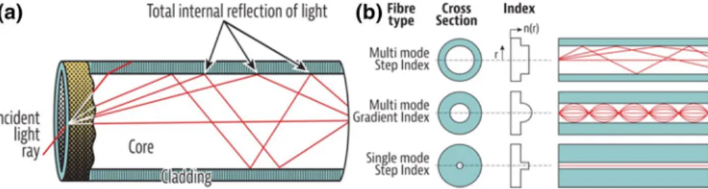
A fibre optic cable used as a data transmission medium consists of a bundle of thin optic fibres. When the modulated light propagates through the fibre, its signal will be enhanced by optical amplifiers and received by a photodetector that converts light to an electrical sig- nal. A single thin optic fibre consists of three primary components: the core, the cladding, and the coating or buffer (Fig. 2). The very thin core in the centre of the fibre, with a small diameter varying from 8 to 63 µm, is a cylindrical rod of dielectric material. The clad- ding that surrounds the core is a dielectric component with a lower refractive index than that of the core. Light propagates primarily along the fibre core, where the core–cladding arrangement creates an optical waveguide that confines the light in the core by total inter- nal reflection at the core–cladding interface. The light traveling through the optical fibre carries information in the same manner as an electrical transmission copper conductor, and data transmission occurs at 99.7% of the speed of light in a vacuum (Rajpoot et al. 2017).
Fig. 1 Simple optical fibre data transmission framework. Modified from Elprocus (2019)
Fig. 2 Basic structure of an optical fibre (a) as modified from Fidanboylu and Efendioglu (2009), and the internal structure of an optical fibre (b) modified from Media (2019)
The coating or buffer encloses the cladding to protect the optical fibre from physical dam- age, preventing abrasions due to its elastic nature, and preventing scattering losses caused by microscopic bends (Jones 1998).
Light travels along the multi-mode fibre optic cable via total internal reflection. Internal back reflection of light inside the multi-mode fibre core occurs first at the critical angle of incidence, as determined by Snell’s law (Mahajan 2014). At any angle of incidence greater than the critical angle, light is reflected into the fibre glass medium (Fig. 3a). Light trav- els down the fibre optic cable by repeatedly reflecting off the walls, with the fibre acting as an electromagnetic surface waveguide (Jones 1998). The optical fibres are classified as single-mode or multi-mode fibres based on the core diameter, and as step-index and gra- dient-index fibres based on the refractive index profile. The mono-mode fibres have a nar- row glass core, most commonly with a core diameter of 8–10 µm, with a uniform refrac- tive index profile and are known as step-index fibres. They transmit only a single mode of light within a specific wavelength range for a linearly polarised state. Multi-mode fibres have a large diametric core, with a core–cladding diameter ratio of 50/125 or 62.5/125 µm, allowing multiple modes of light to propagate, and can be either step index or gradient index (Fig. 3b). The multi-mode gradient-index fibres have a nonlinear, rotationally sym- metric index profile, with the index decreasing from the centre of the fibre outwards (Jenny 2000). This refractive index arrangement causes the light to travel at a constant speed until it reaches the receiver. However, the multi-mode fibres exhibit high dispersion and attenu- ation rates, which degrade the signal quality and limit its long-distance application. In con- trast, the single-mode fibres have a lower attenuation and greater signal length, making them ideal for long-distance applications.
2 Fibre Optic Sensors
The capacity of a fibre to be used as a sensor is its most useful characteristic. When a fibre is used as a sensor, a light beam is converted into an electrical signal, and the sensor measures the physical parameters of the light and translates the information into an out- put read by an instrument. Numerous optical fibre structures, including single-mode fibres, multi-mode fibres, photonic crystal fibres (PCFs), fibre gratings, and surface plasmon resonance (SPR) structures, are used to produce sensors for different applications (Alwis et al. 2016). The fibre optic sensor presented by Momota and Hasan (2018) has a simple hollow-core circular lattice PCF and is based on SPR, which was designed using a finite element method (FEM). An optical fibre sensor’s photosensitivity is the most valuable
Fig. 3 Total internal reflection in a multi-mode optical fibre (a) as modified from Media (2019), and differ- ent mode types of optical fibres (b) modified from Jenny (2000)
characteristic, and used for diverse sensing applications. The photosensitivity indicates a fibre optic sensor’s ability to induce a permanent refractive index variation in an optical fibre when exposed to radiation. The core diameter and the core, cladding and protective sheath materials of the fibre optic cable all affect the sensing system’s overall sensitivity.
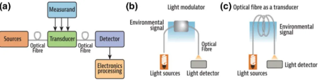
Photosensitivity is utilised in both intrinsic and extrinsic sensor types (Fig. 4), with vari- ous techniques for probing the characteristics of light propagating through the optical fibre.
These characteristics of light include intensity, polarisation, phase, frequency, wavelength, and spectral distribution (Udd 2006).
Intrinsic fibre optic sensors are modulated by an environmental signal, where the sens- ing between the light and the target takes place within the fibre itself. In contrast, extrin- sic fibre optic sensors consist of input and output fibres carrying light to and from a light modulator (Fig. 4). In such cases, the fibre is only used as a light carrier and does not inter- fere with the interaction between the light and the target. These transduction mechanisms enable one to develop a variety of physical parameter detection sensors. These sensors can be configured as point sensors, multiplexed sensors where several sensors are multiplexed per channel to create a sensor network, or as distributed sensors that use the fibre optic cable as a continuous array of sensors (Fig. 5).
2.1 Fibre Optic Geophysical Sensors
Fibre optic sensors are generally applied as point sensors or distributed sensors in geophys- ics. Fibre optic geophysical sensors, which are field-tested and show improvements in sev- eral aspects of geophysical problems, are developed based on one of three types of back- scattering of light (Rayleigh scattering, Brillouin scattering, Raman scattering) or fibre Fig. 4 Measurement principle for a fibre optic sensor (a) intrinsic (b) and extrinsic (c) fibre optic sensors.
Modified from Elprocus (2019)
Fig. 5 Various fibre optic sensor configuration types: point fibre optic sensor (a), multiplex fibre optic sen- sor (b), and distributed fibre optic sensor (c) modified from Michie (2000)
Bragg gratings (FBGs). Back-scattering-based distributed fibre optics geophysical sensors (DFOGSs) measure physical parameters along the length of the fibre. DFOGSs can vary based on the scattered light type, the sensor’s operating principles, the parameters to be measured, the spatial resolution, the time needed to acquire data, the light signal applied, and other factors.
2.1.1 Light Scattering
When an incident light signal transmits through the fibre core, a small disruption in the environment will affect the fibre’s length, diameter, and refractive index and cause the light signal to back-scatter. The changes in the characteristics of back-scattered light are the key to understand what causes the environmental changes (e.g., temperature, strain, etc.). The changes in intensity, phase, and frequency of the back-scattered signal are interpreted to determine the physical parameters’ location and amplitude along the length of the fibre.
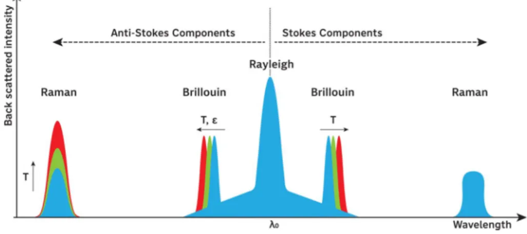
By detecting changes in the amplitude, frequency, and phase of light scattered along the fibre, one can create a distributed fibre sensor for measuring localised temperature, strain, vibration, and pressure over lengths of 1 m to 100 km and more. Such measurements can be made in the time or frequency domain to resolve location information. The continuous back-scattered trace over time, where each time point corresponds to a particular location along the fibre, is converted into distance based on the speed of light in the fibre and the length of the fibre (Udd et al. 2011). Back-scattered light in a fibre optic cable has three components: Rayleigh, Stokes, and anti-Stokes. The Stokes and anti-Stokes components consist of Brillouin and Raman back-scattered light (Fig. 6). Therefore, the back-scattered light spectrum consists of three types of scattering: Rayleigh, Brillouin, and Raman (Ren 2016). The Rayleigh band has the highest intensity, followed by the Brillouin groups and then the Raman bands.
2.1.1.1 Rayleigh Scattering Rayleigh scattering is an elastic process that results from ran- domly occurring inhomogeneities in the refractive index of the fibre core (Fig. 7). Since this scattering is elastic, the frequency of Rayleigh scattering is equivalent to that of the incident light, but has a time delay, which is useful for spatially distributed sensing along the fibre
Fig. 6 Schematics of Rayleigh, Raman, and Brillouin peaks in the back-scattered light spectrum (modified from Frings and Walk 2011). T represents temperature and ε is strain
length. The DAS approach that detects acoustic waves along the fibre length is based on Rayleigh scattering. Rayleigh scattering exhibits a temperature- and strain-invariant refer- ence attenuation distribution, useful for sensing temperature or strain via either Brillouin or Raman scattering (Liu et al. 2016; Martins et al. 2013).
2.1.1.2 Brillouin Scattering Brillouin scattering involves interactions among the incident wave, scattered wave and phonons, and a minimum frequency shift of ~ 11 GHz at 1530 nm.
This frequency shift for a specific incident light signal depends only on the fibre’s acoustic velocity and refractive index. These parameters are determined by the fibre core composi- tion and environmental variables. The Brillouin frequency shift, which is proportional to the medium’s acoustic velocity, is dependent on the environmental conditions and demonstrates a linear relationship with temperature and strain. Therefore, the frequency shift observed in most Brillouin scattered light-based distributed sensors measures the local Brillouin shift due to the change in environmental conditions (Motil et al. 2016). The amplitude and the wavelength of Brillouin scattered light are strain and temperature-dependent. When a con- stant incident light wavelength source is used, the Brillouin scattering wavelength changes with temperature and strain. However, there is a slight frequency shift. The Brillouin back- scattering wave and the incident wave exhibit similar attenuation. However, using a 1550- nm light source, the spatial sensing range can be increased by minimising the loss. The Brillouin signals are approximately 15–20 dB weaker than the Rayleigh signals (Miah and Potter 2017), but they are an order of magnitude stronger than Raman signals. This enables Brillouin-based sensors to have a higher signal-to-noise ratio (SNR), improving the sensor spatial resolution and range.
2.1.1.3 Raman Scattering Raman back-scattering inside the fibre core occurs due to the back-scattering of an incident photon by a molecule. The back-scattered photon will instanta- neously undergo two-state transitions by either producing or absorbing another photon. Like Brillouin scattering, Raman scattering causes a frequency shift of ~ 13.0 THz at 1550 nm.
Raman back-scattering depends on the laser source wavelength and is very sensitive to strain induced in the fibre due to external vibrations. Raman scattering, with one temperature- dependent component and one temperature-independent component, is primarily used in DTS systems to determine temperature changes along the fibre.
Generally, there are certain advantages using one type of back-scattered-based sensor over another depending on the detected physical parameters. For Raman peaks, the anti- Stokes component is temperature-dependent, while the Stokes component is virtually unaf- fected by temperature changes. In the case of Brillouin peaks, temperature affects both the Stokes and anti-Stokes components. Thus, Raman components are ideal for obtaining information regarding the temperature distribution along the optical fibre. The tempera- ture does not influence the amplitude but instead causes a change in wavelength. Using the Raman peaks, one can determine the absolute temperature by analysing the ratios of the Fig. 7 Rayleigh back-scattering
through the core of a fibre optic cable (modified from Jackson 2009)
amplitudes of the anti-Stokes and Stokes components utilising a detector. The Brillouin peaks spread outward from the centre with an increase in temperature. They provide infor- mation about the distributed temperature and distributed strain, which both affect the wave- length shift. This information can then be deconvolved into distinct temperature and strain measurements. The Rayleigh and Brillouin scatterings have the potential for applications in distributed geophysical sensing systems to achieve simultaneous detection of temperature and acoustic parameters. A combination of Rayleigh and Brillouin scattering can be used for simultaneous measurements of vibration and temperature in single-mode fibres with a 1550-nm light source (Miah and Potter 2017). Vibration signals are more important than temperature data for subsurface mapping. Therefore, when a multi-parameter detection system is required for acoustic properties and temperature, a greater emphasis will be given to active vibration detection than temperature measurements.
2.1.2 Fibre Bragg Gratings
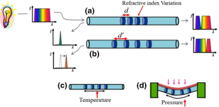
An FBG is a spatially limited periodic variation of the refractive index in the fibre optic core. In 1978, FBGs were demonstrated as a wavelength filter for the first time, based on the discovery of photosensitivity in optical fibres (Hill et al. 1978). Currently, FBGs are produced as inscribed photosensitive fibres by using an intense ultraviolet source, with a typical length of 1–10 mm. As illustrated in Fig. 8a, the periodic refractive index varia- tion leads to an effect like Bragg reflection in atomic crystal layers at a wavelength related to the structure’s periodicity. When light is incident upon the FBGs, only a portion of the incident light intensity (I) at a wavelength λ, in which λ is proportional to the period (d) of the refractive index variation, will be reflected (Fig. 8a). The reflected wavelength will change if the periodicity or refractive index changes (Fig. 8b), enabling the use of FBGs as a sensor. The changes in fibre length due to the temperature or applied strain of the fibre (Fig. 8c) will change the periodicity to a value of d′, which will lead to a corre- sponding change in reflected wavelength. Similarly, pressure can be measured by connect- ing the FBG to a membrane (Fig. 8d). Therefore, FBGs are applied to sense and monitor strain, temperature, and pressure.
FBG sensors are applied as point sensors that can be distributed along the length of a fibre. An FBG system’s characteristic to reflect only part of the energy in a limited wave- length band around its peak wavelength, and allow the remaining energy to pass through it,
Fig. 8 Working principle of FBG-based fibre optic sensors (modified from Lumens 2014)
helps develop multiplexed fibre optics geophysical sensors. This feature enables multiple FBG sensors to be incorporated into a single optical fibre by wavelength division mul- tiplexing (WDM), where FBGs with different peak wavelengths are used for each sen- sor (Hecht 2002). Multiplexed FBG sensors measure physical parameters along the fibre length at a finite number of locations by multiplexing several sensors in the wavelength domain (López-Higuera 1998). Multiplexing FBGs beyond 100 FBGs in the wavelength domain will not extend the sensing element, but an increase in FBG number and sensing length can be achieved by applying time-domain multiplexing (Barrias et al. 2016). The time-division multiplexing (TDM) scheme distinguishes the sensors by the time of flight of a short interrogation pulse.
2.1.3 The Technology and Characteristics of Commonly Applied DFOGSs
Numerous DFOGSs have been developed using different technologies designed to suit different geophysical problems and the variations in back-scattered light. The most com- mon field-tested and applied DFOGS types are Brillouin-scattering-based sensors [opti- cal time-domain analysis (BOTDA) and optical time-domain reflectometry (BOTDR)], Raman-scattering-based sensors (OTDR), Rayleigh-scattering-based sensors [optical fre- quency-domain reflectometry (OFDR) and phase optical time-domain reflectometry (phase OTDR)], and FBG-based sensors. These sensors differ in several aspects, even for a single type of back-scattering of light. For example, the BOTDA sensor is based on stimulated Brillouin scattering, while the BOTDR sensor is based on spontaneous Brillouin scat- tering. The BOTDA technique uses two counter-propagating lasers and takes advantage of Brillouin amplification (Bao and Chen 2011), using direct detection schemes (Fig. 9).
When the BOTDA system is functioning, as indicated in Fig. 9, an optical pump and a probe that supplies a continuous wave (CW) are counter-propagating along the sensing optical fibre so that the optical frequency differences are scanned for the frequency shift.
The acquired Brillouin spectrum is processed further using data processing techniques to find the peak locations of Brillouin frequency (Lu et al. 2019b).
There are limitations in sensing ranges and spatial resolutions of these two types of Brillouin back-scattered light-based fibre optic sensors. There have been works to improve the spatial resolution of BOTDA temperature sensors, and a 2 cm resolution is achieved by Dong et al. 2012 at a minimal sensing range that extends up to 2 km. The BOTDA strain sensors are limited to a spatial resolution of roughly 1 m (Barrias et al. 2016). In practical field measurements using Brillouin back-scattering-based distributed sensors, it is possible to measure a strain with a resolution of a few micrometres over one metre sensing range and a temperature resolution of less than 1 °C (Bao and Chen 2011). The measurand reso- lution can be increased by further processing the acquired data. It is possible to obtain a
Fig. 9 Schematic diagram of the BOTDA sensing scheme (modified from Xue et al. 2018)
temperature resolution of 0.1 °C, by processing DTS data, at well depths of up to 5 km (Brown and Hartog 2002). The Rayleigh back-scattering light-based OFDR sensors have a millimetre spatial resolution (Froggatt and Moore 1998), but they have not been achieved at their current maximum sensing range that extends to 50-70 km. Similarly, a 2 mm spa- tial resolution is achieved using FBG-based sensors (Ferdinand 2014), while extending the sensing range remains a challenge. A comparison of the relative performance of these four types of DFOGS technologies applied in different geophysical applications is presented in Table 1.
Different performance parameters are preferred by individual users for each application, depending on their needs and requirements. Hartog (2017) outlined the evaluation parame- ters for distributed fibre optics sensors’ performance, namely measurement resolution, spa- tial resolution, sensing range, and measurement time. The four parameters are independent, with trade-offs making up the whole system’s performance. The improvement of one factor often necessitates a compromise in another. For example, OTDR systems can measure over 100 km with a spatial resolution of several metres. The OFDR can achieve millimetre reso- lution, while its sensing distance is usually limited (Yuksel et al. 2009). SNR is the vital factor linking the interdependence of the four parameters. It directly determines the meas- urement resolution and finally limits the spatial resolution, sensing distance, and measure- ment average time (Hartog 2017).
At present, DFOGSs are an attractive technology that offers superior performance and advantages over conventional wireline geophysical sensors. These sensors are ideal for applications in which reliability in a changing environment is essential. DFOGSs will become more accustomed and cost-effective in the future when new technology becomes more familiar. Sensor-producing companies are addressing multiple market segments, and current energy companies are the dominant market. The simultaneous fibre optics sensor systems, comprising DAS systems compatible with DTS systems using the same optical fibre cables, showed significant market penetration powers (Muanenda 2018). The distrib- uted fibre optic sensor (DFOS) market analysis for 2014–2025 by Research and Markets (2017) indicated that the oil and gas market alone would have an increase of 19% in total.
3 Application of Fibre Optics Sensors in Geophysical Studies
The use of fibre optic sensors in geophysics began in the oil and gas industry, with a fibre optic pressure sensor applied in a well in 1993 (Baldwin 2014). Subsequently, fibre optic sensors have been employed as temperature and pressure gauges to monitor unconventional reservoirs and enhanced hydrocarbon recovery (Rehman and Mendez 2012). Therefore, single-point fibre optics sensors, installed at the end of the fibre optic cable, were the first to be applied in the oil and gas industry for pressure and temperature measurements in the 1990s. Numerous point sensors are placed at multiple points along the fibre to make quasi- distributed sensors (Li et al. 2015). Although the use of fibre optic sensors is less common than that of other conventional geophysical techniques (electrical, magnetic, seismic, etc.), their geophysical application is in progress, particularly as distributed sensors (DAS, DTS, DPS) and simultaneous detection of multi-physical parameters. Field experiments on the fibre optic cable enable different fibre cable schemes for high-power and high-definition live camera data transmission mechanisms inside a borehole.
Table 1 Requirements and performance of different fibre optic geophysical sensing techniques Brillouin-basedRaman-basedRayleigh-basedFBG-based BOTDABOTDRRaman OTDROFDRPhase-OTDRFBG Transducer typeDistributedDistributedDistributedDistributedDistributedQuasi-distributed Main measurandTemperature and strainTemperature and strainTemperatureTemperature and strainDynamic measurementTemperature and strain Sensing range150–200 km (Bao and Chen 2012)20–50 km37 km (Park et al. 2006)50–70 km131.5 km (Peng et al. 2014)100 channels Spatial resolution2 cm (Dong et al. 2012) ~ 1 m (Barrias et al. 2016)1 cm (Tanner et al. 2011)1 mm (Froggatt and Moore 1998) ~ 0.5 m (Qin et al. 2012)2 mm (Ferdinand 2014) Dynamic measure- mentsYesNoNoYesYes- Detection schemeDirectCoherentDirectCoherentCoherent and direct-
3.1 Distributed Acoustics Sensors (DAS)
DAS is a fibre optic geophysical technique that deploys fibre optic cable instead of con- ventional geophones to record acoustic signals. It works by interrogating the Rayleigh back-scattered signals caused by the strain along the fibre optic cable due to the propaga- tion of seismic waves (Molenaar 2013). The channels that sense elastic waves in the fibre optic cables are at a specified distance so that DAS can be used as an array of designed 1-component geophones to measure deformations along the fibre length. It resembles an array of geophones with higher density along its length. The spacing between adjacent receivers and the fibre’s sensing length is generally determined before the survey. The light pulse generating rate is much higher than a seismic frequency, typically in the range of 10–100 kHz with the possibility to be regulated with a high rate corresponding to high SNRs and vice versa (Li et al. 2015).
DAS is a relatively well-established fibre optics sensing method in geophysical surveys, especially in a borehole survey environment in the form of vertical seismic profiling (VSP).
Initially, a DAS VSP’s field experiment was tested by Shell Canada in 2009, followed by the test of Mestayer et al. (2011) for its capability to replace conventional geophones. The results of DAS VSPs are either compared to traditional VSP surveys or validated by experi- mental results (Jreij et al. 2018; Ghahfarokhi et al. 2018; Reinsch et al. 2015). Companies that tested DAS systems of 3D multi-well VSP, deep water time-lapse VSP, and low-foot- print monitoring included Silixa (Parker et al. 2013; Daley et al. 2013), OptaSense (Mes- tayer et al. 2012), Schlumberger (Barberan et al. 2012), and Halliburton (Barfoot 2013).
DAS has been applied for single-parameter detection in a borehole (Bakku et al. 2014a, b;
Harris 2017; Li et al. 2015; Nesladek 2017; Silkina 2014) and has provided high-resolution data for the energy and environmental sectors (Daley et al. 2013, 2016; Dean et al. 2015).
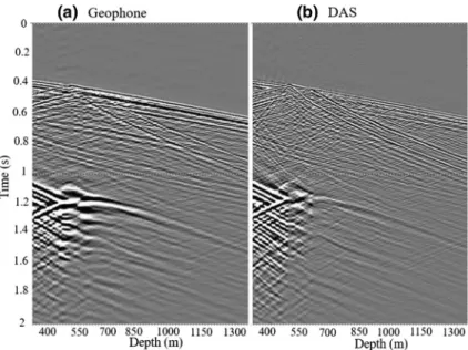
DAS and geophone VSP data by Mestayer et al. (2011) are compared in Fig. 10. At the beginning of the data recording times, the DAS and geophone systems receive a similar signal, while as time goes by, more noise is recorded in the DAS system than the geophone system. The velocity profile obtained from DAS VSP matched well with the geophone VSP
Fig. 10 A comparison of the seismic signal recorded by DAS VSP (a), conventional geophone VSP (b), a velocity profile comparison between DAS VSP (red), geophone VSP (blue), and sonic logging (green) (c) modified from Mestayer et al. (2011)
and the sonic log velocity profiles demonstrating DAS’s capability to replace conventional geophone VSPs and the sonic log measuring system.
The recent developments in fibre optic sensing systems by the Silixa company will potentially increase the applications of DAS VSP for permanent reservoir monitoring and 4D seismic VSP recording. Silixa developed a high-resolution advanced DAS sys- tem called ‘Carina’ with precision-engineered constellation fibre optic cable having 100x (20 dB) improved back-scatter light compared to that of standard fibre (Naldrett et al.
2020). The new system has high sensitivity, wide dynamic range, broadband, and wide- aperture response that benefits from acquiring high-resolution 4D seismic images. The VSP data were acquired using a 15-level conventional geophone array at 11 data positions along the wellbore and using a DAS Carina sensing system by installing the improved fibre optic cable cemented behind the casing simultaneously (Fig. 11). The field test result showed that the enhanced DAS system recorded high-resolution images along the entire depth of the wellbore compared to the geophone VSP data.
DAS has been applied in microseismic measurements, well and reservoir surveillance, hydraulic fracturing monitoring, and diagnostics, earthquake detection, and potentially has excellent capability to replace conventional geophones and seismometers (Bakku et al.
2014a, b; Lindsey et al. 2017). The DAS capability for reservoir monitoring showed that DAS presents enough repeatability for time-lapse applications (Harris 2017; Naldrett et al.
2020). Molenaar (2013) explained that DAS is useful in both open, cased, and cemented boreholes, hydraulic fracturing monitoring, and diagnostics providing essential informa- tion about boreholes such as a quantitative assessment of injection rates and injection flu- ids. DAS presents information on the estimation of production profiles, injection profiles, multi-phase flow, well-integrity, and production monitoring (Li et al. 2015) for wells and reservoir surveillance. Besides borehole survey and reservoir monitoring, DAS is applied in near-surface and ocean bottom seismic wave detections. Field tests have used the
Fig. 11 A comparison of a seismic signal record along with the entire depth of the wellbore. Stacks of five shots at 11 tool positions recorded using conventional geophones (a) and stacks of 5 shots recorded using a DAS Carina system (b) modified from Naldrett et al. (2020)
standard telecom fibre optic cable networks buried below ground and ocean bottoms as active and passive seismic wave detectors. The p- and s-waves can be identified from near- surface earthquake sources.
Conventional seismometer coverage is limited to a handful of permanent ocean bot- tom stations. Recent experiments based on fibre optic telecom cables on the ocean floor, called dark fibres, present a promising method for detecting earthquakes. Marra et al.
(2018) detected earthquakes over 75–535 km, with epicentre distances ranging from 25 to 18,500 km. In a near-surface study using fibre optic cables, Jousset et al. (2018) meas- ured the dynamic strain from earthquake waves of both natural and man-made origin. The authors collected strain data with a spacing of 4 m along a 15 km fibre optic cable system on the Reykjanes Peninsula in southwest Iceland, identifying structural features such as normal faults and volcanic dykes. Research conducted at Stanford University demonstrated that fibre optic cables could continuously monitor seismic conditions and earthquakes (Tech 2018). The DAS near-surface seismic survey measures active seismic waves deploy- ing the fibre optic cable at 0.8 m depth below the surface in a similar manner to geophone survey lines (Pevzner et al. 2017). DAS surveys have also been applied to study hydrologi- cal changes in basins, with shallow structural mapping and groundwater depth determina- tion (Ajo-franklin et al. 2019). Thus, fibre optic sensors are considered essential tools for the future of both near-surface seismic surveys and seismology.
The use of DAS in all geophysical applications offers certain advantages over geophones and hydrophones. Its use, particularly in borehole seismic surveys, has benefits such as long equipment survivability, dense spatial sampling, and full well coverage, making it uniquely suited for permanent reservoir monitoring (Correa et al. 2019). It has numerous advantages compared to conventional 1-component geophones. It can be used in various well types (e.g. horizontal well or ultra-slim well) due to its slim cable, and the fibre cable is easily installed together with other optical fibre sensors like DTS and DPS. Unlike a geo- phone, DAS can obtain measurements with complete vertical coverage of a well without fibre movements. DAS is non-intrusive, which means it can be used in an exploration well, production well, and observation well without postponing production.
Although DAS has several advantages compared to conventional geophones and is a rapidly developing technology, limitations might hinder its widespread application. This may include low SNR, uncertainty in channel depth, lack of transverse sensitivity, diffi- culties in determining the optimum gauge length, and only one-component measurements.
There have been tests to reduce these limitations and apply DAS technology more widely.
These include de-noising data processing techniques using a band-pass filter, median filter, and stacking of multiple fibre optic measurements that can remove the time-variant noise generated from temperature fluctuations in the well and optical noise (Bakku et al. 2014a, b). A helically wrapped cable (HWC) design was introduced to improve the fibre optic cable’s transverse sensitivity and broad-side wave detections (Hornman et al. 2013). Its fibre arrangement has been theoretically described by Kuvshinov (2016) and tested in field experiments by Hornman (2017). The recent work by Silixa (Naldrett et al. 2020) achieved DAS data with 100 times better SNRs than ordinary fibre cable. Moreover, the accurate determination of DAS’s receiver channel depth using tube wave reflections and check shots is a useful method to calibrate the receiver channels in-depth (Li et al. 2015). There has been progress to express the optimum gauge length prior to the DAS survey as it affects both SNR and resolution of DAS data (Bakku et al. 2014a, b; Dean et al. 2016; Li et al.
2015; Yang et al. 2019).
3.1.1 DAS Gauge Length
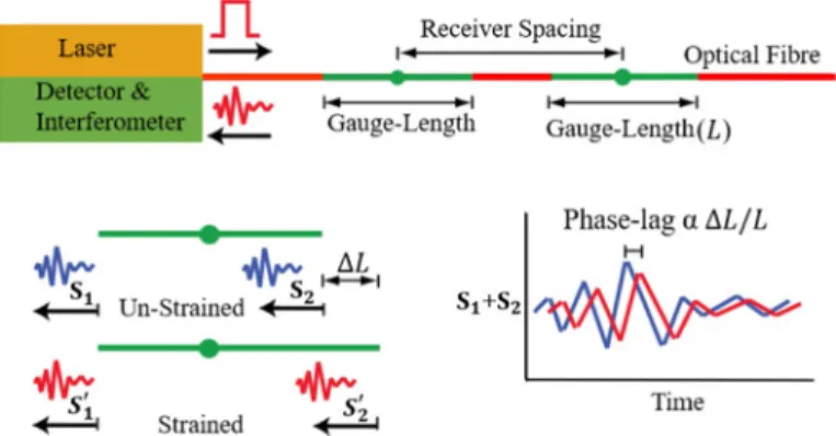
DAS data quality is affected by the length of the sensing part of the fibre optic cable called the gauge length (L). The strain measurement in distributed fibre optics sensing cable is not at individual points like point sensors or conventional geophones; instead, it is acquired across a gauge length of the fibre. The strain is summed along the gauge length and defined in the digital rather than the optical domain (Dean et al. 2015). The underlying principle behind COTDR operation is to analyse the phase difference between the back-scattered signals from two points separated by a gauge length (Bakku et al. 2014a, b; Li et al. 2015).
An axial strain is obtained by analysing the perturbed phase difference between back-scat- tered lights from two points (Ning and Sava 2018). The phase lag is interrogated every- where along the fibre, enabling the whole fibre to become a sensor (Fig. 12). When data are acquired using DAS systems, the signal due to the light pulse’s first emission is back- scatted at the front and end of the gauge length (S1 and S2), and its sum for unstrained fibre is S1 + S2. When the fibre is strained, the sensing part will be changed by ΔL, and the gauge length will become L + ΔL so that the corresponding back-scattered signal at the front and end of the gauge length for the strained fibre will be S′1 + S′2. The analysis of the phase lag between S1 + S2 and S′1 + S′2 enables one to obtain the strain along the fibre.
A larger gauge length corresponds to better SNR but lower spatial resolution and vice versa (Bakku et al. 2014a, b). If too large a gauge length is used, the resolution will be reduced, and the wavelet’s shape will be distorted (Dean et al. 2016). Numerous DAS works used different gauge length values: 1 m (Ning and Sava 2018; Daley et al. 2013), 10 m (Fernández-Ruiz et al. 2020), and achieved acceptable SNR. Farhadiroushan et al.
(2016) showed that the gauge length can be reduced to 5 cm while maintaining a sufficient SNR using specifically designed optical fibres. The choice of the most suitable sensing gauge length, called the optimum gauge length (Lopt) that considered both SNR and resolu- tion effects, is essential and should be made before DAS data acquisition. The works by Dean et al. (2015), Dean et al. (2016), and Yang et al. (2019) used the concept of Ricker wavelet as a better representation of seismic wave/strain and its temporal and spatial wave- length to drive the formula that better represents the Lopt of straight fibre optic cable.
According to these works, a seismic wave is represented by a Ricker wavelet in the time domain as:
Fig. 12 The gauge length in the DAS system (Bakku et al. 2014b). The receiver spacing, also called chan- nel spacing, refers to the distance between consecutive average strain measurements within a gauge length (modified from Ning and Sava 2018)
where fp is the peak frequency. A Ricker wavelet that travels with velocity 𝜈 is expressed in the space domain as:
where κ = (√𝜈𝜆6∕𝜋)
t is the wavenumber. The spatial wavelength of the wave ( 𝜆s ) that repre- sents the distances between two minima in the space domain is related to the temporal wavelength ( 𝜆t) as 𝜆s = ν 𝜆t . The graphical presentations of the Ricker wavelet in the time domain are given in Fig. 13(a).
Dean et al. (2016) expressed the strain (ε) applied on the fibre due to the Ricker wavelet that propagates in the x-direction with velocity ν in the time domain as:
The total change in the fibre length (ΔL) due to the applied strain at position x that in turn causes a change in the phase of the back-scattered light is equal to the integral of the strain along its lengthand the strain measured by the fibre is given by
(1) R(t) =(
1−2𝜋2fp2t2) e−𝜋2fp2t2
(2) R(x) =(
1−2𝜋2k2x2) e−𝜋2k2x2
(3) 𝜀(t, x) =
(
1−2𝜋2fp2( t−x
𝜈 )2)
e−𝜋
2fp2( t+x𝜈)2
ΔL=
L 2
∫
−L 2
𝜀(t, x) =
L 2
∫
−L 2
(1−2𝜋2𝜅2x2)
e−𝜋2𝜅2x2dx=xe−𝜋2𝜅2x2]
L 2
−L 2
ΔL=Le−𝜋2𝜅2 L
2 4
(4) 𝜀fibre= ΔL
L
Fig. 13 The Ricker wavelet curve in the time domain (a) and gauge length-to-temporal wavelength ratio curves (b) (modified from Yang et al. 2019). The horizontal time between two minima represented by the red line is the Ricker wavelet’s temporal wavelength (λt) in the time domain
Therefore, as the gauge length gets smaller, the value of strain measured by the fibre approaches the maximum amplitude of the actual strain (i.e. as L → 0, εfibre→ εmax). The maximum value of ΔL(Lmax = Le−𝜋2𝜅2 L
2
4 ) occurs when the gauge length (L) is equal to λs/√
3 implying that the maximum strain will be measured when the gauge length is as small as possible. Likewise, the error in the measured strain (E(𝜀f )) is given by;
and the corresponding SNR on the measured strain data is given by
Therefore, the peak SNR value will occur where the value of ΔL is a maximum (i.e. when the gauge length/spatial wavelength = 1/√
3).
Furthermore, the graphical relationship between the gauge length-to-spatial wavelength ratio (Fig. 14) and the resulting waveforms for different gauge length values indicates that the waveforms become more distorted as the gauge length-to-wavelength ratio increases.
When the gauge length is larger than the spatial wavelength (ratio > 1), the maximum value is no longer located where the centre of the gauge length coincides with the centre of the wavelet. The optimum gauge length determination requires close observation of the rela- tionships of SNR and resolution with gauge length values. The graph of SNR versus gauge length-to-spatial wavelength ratio indicates that values between 0.40 and 0.77 represent the range of ratios where SNR > 90% of the maximum (Fig. 14a). This is the range of val- ues where the resolution values should be included. Dean et al. (2016) used the resulting wavelength (as a proxy to resolution) versus gauge length to spatial wavelength (Fig. 14b) to perceive the resolution effect. The green line indicates the gauge length-to-spatial wave- length ratio is 50% and the resulting wavelength values where the wavelength is 15% of the actual wavelength (Dean et al. 2016; Yang et al. 2019). According to these values, the over- lap between the two sections, where the SNR is greater than 90% of maxima and deviation of the resulting wavelength is lower than 15%, occurs at the optimal gauge length-to-spa- tial wavelet ratio values 0.402 and 0.54. Therefore, the optimal gauge length is expressed
(E(𝜀f)) =E(ΔL) L
SNR= ΔL∕L (5) E(ΔL
L
) = ΔL E(ΔL)
Fig. 14 The effect of gauge length-to-spatial wavelength ratio on the SNR (a) and resulting wavelength deviation (b) (modi- fied from Dean et al. 2016)
by optimal ratio values between 0.402 and 0.54, and spatial wavelength (λs) of the Ricker wavelet is given by:
where ratio represents the desired gauge length-to-spatial wavelength ratio (Dean et al.
2016; Yang et al. 2019).
If the attributes vary considerably along the survey line during DAS data acquisition, multiple gauge lengths can be used (Dean et al. 2016). Furthermore, the strain detection by HWC is different from the straight fibre, and the optimum gauge length expression is dif- ferent. Yang et al. (2019) conducted a theoretical analysis of optimal gauge length determi- nations for DAS measurements using HWC, though it remains to be confirmed with actual field experiment results. The work proposed an optimum gauge length expression that con- siders SNR and resolution as:
where the ratio value varies from 0.402 to 0.5, similar to straight fibre, α is the fibre cable’s wrapping angle, and θ is the incident angle for a situation where the impinging Ricker wavelet does not travel along the HWC and creates an incident angle of θ.
3.2 Distributed Temperature Sensors (DTS)
DTS is the second most commonly applied fibre optic sensing system in geophysical appli- cations. These sensors are applied to measure temperature mainly within a borehole sur- vey environment in the energy and environmental sectors. Studies have reported the use of DTSs in boreholes (for example, Patterson et al. 2018; Read et al. 2015; Siska et al. 2016;
Zhang et al. 2018a, b). DTS systems are beneficial for temperature measurements in harsh environments that require rugged designs. DTSs have been applied in environments with working temperatures of 300 °C, and others with pressures exceeding 20,000 psi (1379 bar) (Baldwin 2014). The high-temperature regenerated fibre Bragg gratings (FBGs), inscribed in high-attenuation fibres and standard telecom fibres as temperature sensors, are used to measure heat transfer optically powered by heating elements induced by gas flow for tem- peratures ranging from room temperature to 800 °C (Chen et al. 2014). DTSs are not lim- ited to measuring temperature values, but also as a distributed borehole flowmeter. The flowmeter consists of an armoured fibre optic cable and utilises the active DTS (ADTS) technique, where the difference in temperature between a heated and unheated cable is a function of the fluid velocity. For example, based on the ADTS technique of flowmeter design, an increase in flow velocity from 0.01 to 0.3 m/s2 elicited a 2.5 °C cooling effect in a fractured rock aquifer (Read et al. 2014).
3.3 Distributed Pressure Sensors (DPS)
Fibre optic sensors have been used to detect pressure over the past two decades in the energy and environmental sectors. Masoudi et al. (2013) measured a dynamic strain per- turbation along 1 km of a single-mode telecom fibre with a spatial resolution of 2 m over a frequency range of 500–5000 Hz. Additionally, Domingues et al. (2018) demonstrated (6) Lopt= ratiov
fp =ratio× 𝜆s
(7) Lopt(HWC)= ratio× 𝜆s
sin𝛼cos𝜃
the possibility of manufacturing a cost-effective fibre optic pressure sensor based on intrin- sic Fabry–Perot interferometric microcavities. This fibre optic pressure sensor can monitor pressures up to 900 kPa, with sensitivities reaching 59.39 ± 1.7 pm/kPa. Yang et al. (2018) demonstrated a gas pressure sensor based on an anti-resonant reflectance guidance mecha- nism in a quartz capillary tube with an open cavity. This fibre optic pressure sensor had a sensitivity of 4.278 nm/MPa.
3.4 Simultaneous Detection of Multi‑parameters
Recent potential applications of DFOFs have been to detect more than two parameters simultaneously in a borehole. For example, DAS has been combined with DTS, also known as hybrid acoustics and temperature sensing (Miah and Potter 2017; Muanenda et al.
2016), and distributed strain and temperature measurements have been combined (Masoudi et al. 2013; Muanenda et al. 2016; Yahei et al. 2009). A hybrid distributed acoustic and temperature sensor (DATS), using a standard single-mode fibre optic cable, was reported to measure temperatures with an accuracy of less than 0.5 °C at a spatial resolution of 5 m (Muanenda et al. 2016). Three parameters have also been simultaneously measured in boreholes, using a multi-parameter distributed fibre optic sensing system for strain, tem- perature, and vibration (Zhang et al. 2016), and a method for microseismicity, strain, and temperature during hydraulic fracturing (Karrenbach et al. 2019).
A DTS log well intervention methodology developed by the Ziebel company known as
‘Ziebel ZipLog’ has a DTS cable within a carbon rod. It has been employed to measure production and injection wells’ temperature, especially in horizontal wells with up to a 90°, bend for reservoir monitoring (Fig. 15a). The Ziplog technology enabled one to detect the horizontal inflow and injection allocation in wells (Hansen et al. 2009) and was later improved to incorporate six fibre optic cables (Danardatu et al. 2014). The improved semi- stiff carbon rod contains two multi-mode fibres for DTS, one single-mode fibre for DAS, three single-mode fibres for point pressure, point temperature, and vibration measurements (Fig. 15b). Assembling the point pressure and temperature sensors at the bottom of the hole, the company conducted a field trial in a horizontal well and obtained temperature and acoustic data, in conjunction with bottom hole data, that gave comprehensive information for real-time surveillance and dynamic well analysis (Danardatu et al. 2014).
Fig. 15 (a) The Ziebel Ziplog DTS system in a highly deviated well (modified from Hansen et al. 2009) and (b) a semi-stiff carbon rod with six fibre optic cables to record multiple data at a time (modified from Dan- ardatu et al. 2014)
Integrating the different measurements obtained simultaneously helps to monitor the well conditions better. DAS and DTS’s combined data gathered from the same well offer the best use of that information to monitor the well’s conditions for its life. For example, during hydraulic fracturing of an unconventional well, DTS is used for geothermal acqui- sition, cement monitoring, and perforation monitoring. DTS data as a thermal tracer can be used to identify the injection profile and augment the temperature profiles obtained by DTS with those from DAS. Moreover, DAS can be used to get DAS VSP data along the well and can provide data to monitor offset wells that are being fractured (Silkina 2014).
Thus, fibre optic sensor integration to detect more than two parameters simultaneously is advantageous.
3.5 High energy Transmission and Downhole Camera
Fibre optic cables can transmit an enormous amount of energy, reaching 50 kW, for down- hole studies requiring high energy inputs, which cannot be accommodated by conventional wirelines. Fibre optic cables are also used in downhole laser cutting technology, a cost- effective alternative for cutting production tubes, casing, and drilling pipes. They provide downhole laser pipe cutting technology with real-time feedback on the cutting process and cutting depth control for preventing damage to the outer pipes. These applications are ena- bled by armoured optical fibre cables that are resistant to mechanical and chemical damage caused by energy transmission. Armoured fibre cables can transmit information at a speed of 6000 Mbit/s, which is approximately 100 times faster than standard wireline cables.
However, these cables cannot be used as distributed sensors due to their reduced sensi- tivity. Fibre optics has recently been applied in hard-scale mineralization build-up, laser removal technology to remove hard scales from production tubing, and downhole cameras (Zerlux 2019). The downhole camera application of single-mode fibre optic cables allows visual inspection within the wellbore, even in low visibility and extreme wellbore condi- tions of up to 180 °C and 10,000 Psi (690 bar). The presence of fibre cables and the devel- opment of technology in digital data compression enables the transmission of colour and live full high definition (HD) videos at borehole depths of up to 6000 m (Zerlux 2019).
4 Limitations, Challenges, and Future Possibilities 4.1 Limitations
The new geophysical techniques based on fibre optic sensors are still under development in cables, sensors, field measurements, and data processing techniques. The development of specific methods, such as DTS and DAS, primarily occurs at technical universities, tel- ecom industrial entities, oil and gas industrial entities, and research institutes. The stand- ard optic fibres, both single mode and multi-mode, used for sensing and data transmission in geophysical applications, require improvements to pass light within them with mini- mum reflection, scattering, and attenuation. It is difficult to distinguish between changes in back-scattered light that arise from temperature, vibration, and strain fluctuations, and changes caused by inherent fibre loss when using standard fibres (Miah and Potter 2017).
Fibre optic sensors that measure ground vibration along the cable length must differenti- ate between noise and acoustic reflected waves and need improvements to detect minimal environmental changes.
Nonlinear effects and dispersion profoundly affect the sensitivity and spatial resolu- tion of fibre optics sensors, while dispersion also causes attenuation. Thus, we suggest that future research on fibre optic methods of prospecting focuses on developing new fibres with low loss and dispersion over the entire wavelength range of 1300–1650 nm. It is pos- sible to detect various physical properties using fibre optical sensors in the laboratory, while only a few are field-tested and applied to geophysical problems. Therefore, efforts are required to change these fibre optical sensor techniques from the laboratory scale to the field scale with a reasonable sensing range, spatial resolution, and measurement sensitivity.
The long-distance cable suffers from decreased mechanical strength as it is susceptible to breakage due to natural phenomena such as major earthquakes and fire (Lu et al. 2019a).
The non-armoured fibre optic cables used as sensors are susceptible to physical damage, restoration problems, backup issues, and survivability problems and are more fragile than electrical wires. This new technology requires high installation and cable costs, expensive precision splicing, and specialised test equipment for different parameter measurements.
Fibre losses and chromatic dispersion affect the bit rate via pulse broadening, limiting the system performance, and therefore present some disadvantages of fibre optic sensors for geophysical applications. Other challenges in applying the technology include fibre cable coupling with the ground, optical attenuation, and lack of broad-side sensitivity of the fibre cables.
4.1.1 Fibre Cable Coupling
Coupling between the fibre optics cable and the ground is a challenge in applying fibre optic sensors for geophysical surveys. In conventional land-based seismic surveys, geo- phones are either planted on the ground for surface seismic profiling (SSP) or mounted inside the borehole for VSP. However, the coupling between the cable and the medium remains a significant challenge for distributed fibre optic systems. Particularly for vibration measurements, an efficient transfer of source energy to the receiver is critical, requiring strong coupling between the cable and the medium (Munn et al. 2017). It is challenging to deploy the cables inside formations during vibration measurements in borehole environ- ments and more challenging to clamp the fibre cables into the borehole wall like conven- tional geophones. Coupling is a significant factor in DAS VSP survey data quality, and sev- eral field experiments have proposed multiple coupling options. Cementing on the outside of the casing, clamping on the production casing, and inside the tubing (Correa et al. 2019;
Li et al. 2015; Mateeva et al. 2014) are among field-tested coupling options (Fig. 16).
Cementing the fibre optic cable to the borehole wall provides the optimal coupling technique in terms of data quality (Li et al. 2015) and presenting a similar SNR to geo- phone VSPs (Correa et al. 2017). Olofsson and Martinez (2017) used single-mode fibre optic cable cemented behind the casing and obtained a relatively low signal loss and mini- mal environmental noise through a 5.4-km-long fibre optic cable. Cementing to the wall and clamping to the production tubing may be suitable for deep boreholes. These coupling techniques have practical difficulties in shallow boreholes which may not have a well cas- ing that extend beyond the top of the bedrock, or the production tubing may not be present at all. The field test experiment by Munn et al. (2017) proposed a coupling technique anal- ogous to a fully cemented deployment in that the cable was continuously coupled directly to the formation with the use of a flexible borehole linearly inflated using hydrostatic pres- sure (Fig. 16). However, the coupling technique cannot be used for deep boreholes due to its depth limitations of up to 425 m.