CHAPTER 12
RHEOLOGY OF LUBRICATION AND LUBRICANTS A. Bondi
I. Fluid Lubricants 444 1. Normal Fluids 444 2. Non-Newtonian Flow of Oils 452
3. Flow Properties and Hydrodynamic Lubrication 454
II. Gelled Lubricants 457 1. Lubricating Greases 457 2. Flow Properties of Frozen Oils 463
3. Motion of Gelled Lubricants through Pipes 464 4. Hydrodynamic Lubrication with Gelled Lubricants 467
III. Flow Phenomena in Boundary Lubrication 467
1. Friction of Solid Surfaces 467 2. Lubricated Boundary Friction 474
Nomenclature 478 The primary objective of lubrication is the separation of the rubbing
surfaces by a layer which is more easily deformable than the material of the rubbing bodies. This is most successfully accomplished by the hydro- dynamic lifting forces of a liquid layer relative to which the rubbing bodies are moving. In some instances it is desirable to impart a small yield strength to the fluid lubricant and gel it, in order to facilitate the sealing of bearings.
This conversion has relatively little effect on the mechanics of lubrication ai d can be handled by the classical methods of continuum physics. In the life of all rubbing machine elements there are time intervals, sometimes of fairly long duration, during which complete separation of the solid surfac:s is not possible. The load is then only partly carried by the fluid film and partly by the asperities of the rubbing bodies. Layers of suitable solid or semisolid, usually adsorbed, lubricants reduce, but do not entirely prevent metal-to-metal contact under these conditions. The quantitative treatment of this complex situation is, in spite of considerable efforts, only in its infancy.
The following review will attempt to summarize currently available information on the fundamentals of lubrication and the relevant flow properties of lubricants with only minor attention to historical develop- ments.
443
444 A . B O N D I I. Fluid Lubricants
1. N O R M A L F L U I D S
The only physical property of real importance in journal and slider bearing applications is the viscosity. Exact quantitative treatment of the energy balance and temperature, and therefore viscosity and pressure, distribution throughout the lubricant layer requires in addition also the knowledge of density, heat capacity, and thermal conductivity of the lubricant. The fluids of practical interest differ only very little in the latter three properties, while their viscosity may vary over more than six decades within the temperature and pressure range of interest. Many bearings operate over a sufficiently wide range of temperatures and pressures that the variation of viscosity with temperature and pressure has to be con- sidered when making exact calculations for bearing design.
The requisite viscosity-temperature-pressure data are now available for most groups of commercially important natural and synthetic lubricat- ing fluids. An extensive effort to obtain this information has recently been made as a joint project of the American Society of Mechanical En- gineers and of Harvard University.1 The large number of published data calls now for a concentrated effort to systematize the available information.
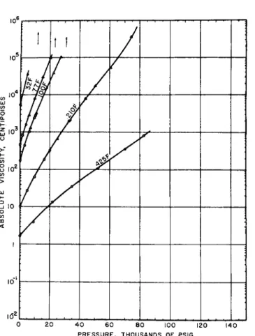
That such a systematization will be no easy task is at once apparent from an inspection of the data in Figs. la-d. The shapes of the viscosity-tempera- ture-pressure diagrams of lubricating fluids differ even in their qualitative aspects so considerably that a generally valid and practically useful formula for the description of these data is very difficult to imagine.
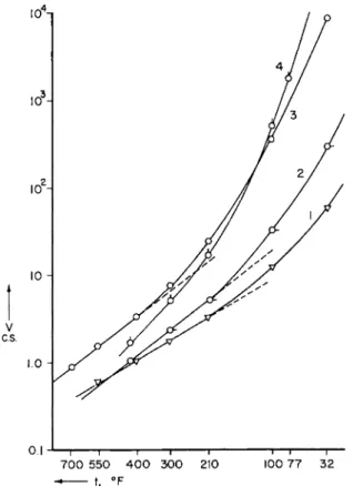
A few viscosity-temperature isobars and viscosity-pressure isotherms of several classes of lubricating fluids are shown in Figs. 2-3. The choice of the ordinates log η vs. 1/T and vs. Ρ was dictated by the desire to demonstrate the deviation from the behavior demanded by simple theory.2 ,3
Many attempts have been made to straighten the η(Τ) function empirically.
Best known of these is the plot of log2 (v + a) versus log Τ (where ν is the kinematic viscosity in centistokes and a is 0.8 as proposed by Walther4
and adopted in many countries as the standard method of plotting the viscosity-temperature data of petroleum-derived lubricants.5 Since its usefulness depends upon the choice of units of viscosity, it can hardly have any theoretical significance. It is, however, surprisingly general and gives straight-line plots over a fairly wide temperature range for many
1 D . Bradbury, M. Mark and R. V. Kleinschmidt, Trans. Am. Soc. Mech. Engrs.
73, 667 (1951).
2 A. Bondi, "Physical Chemistry of Lubricating Oils." Reinhold, New York, 1951.
3 A. Bondi, in "Rheology" (F. R. Eirich, ed.), Vol. I, p. 321. Academic Press, New York, 1956.
4 C. Walther, Erdöl u. Teer 4 , No. 29/30 (1923); 5, No. 34 (1929).
5 American Society for Testing Materials Method D 341-43.
RHEOLOGY OF LUBRICATION AND LUBRICANTS 445
FIG. la. Change of viscosity with pressure at three temperatures for a few typical lubricants.1- 2 Curve 1: bis(2-ethylhexyl) sebaeate. Curve 2 : ll-a-decalin heneicosane (temperatures: 2 0 , 9 9 , 204°C.); 7720 = 1 . 0 2 , 7799 = 0 . 0 5 2 , 17204 = 0 . 0 1 2 poise. Curve, 3 :
l,l-bis(cyclohexylethyl) n-nonane (temperatures: 2 0 , 9 9 , 2 0 4 ° C ) ; »720 = 0 . 7 3 , 7799 = 0 . 0 4 , 77204 = 0 . 0 0 9 poise. Curve 4 : polybutene; 7725 = 1.00,7799 = 0 . 0 5 , 7721s = 0 . 0 1 0 poise.
Curve, 5 : polybutene; 7725 = 2 0 . 0 ,7 7 9 9 = 0 . 1 6 , 77218 = 0 . 0 1 6 poise.
lubricating fluids. Serious deviations from linearity have recently been observed for several types of synthetic lubricants described in Table I.
The Antoine equation, often used for the correlation of vapor pressures, has also been found to represent the viscosity-temperature function of oils tolerably well:6' 6 a'6 b
-β
log η = A + T c ( 1 )
6 F . Gutmann and L . M . Simmons, J. Appl. Phys. 23, 9 7 7 ( 1 9 5 2 ) . 6A H . Vogel, Physik. Ζ. 22, 6 4 5 ( 1 9 2 1 ) .
6 b U. Rost, Kolloid- Ζ. 142, 1 3 2 ( 1 9 5 5 ) ; Erdöl u. Kohle 8, 4 6 8 , 5 4 9 ( 1 9 5 5 ) .
446 A . B O N D I
3 ιο
Ο
10
!
I Iί Α
/
7 /
20 4 0 6 0 8 0 100 120 PRESSURE, THOUSANDS OF PSIG
140
FIG. lb. Viseosity-temperature-pressure relations for poly(dimethylsiloxane) fluid.1
Another three-constant expression has been proposed by Cornelissen and Waterman7
log ν = A + (B/Tx)
where χ has been found to take on values between 2 and 5, for mineral oils being generally near 3. The same equation with χ — 3 had been ob- tained earlier for the viscosity of alcohols and polyols.8 The awkwardness of dealing with three constants of no particular physical significance will probably preclude widespread use of these expressions, unless general relations between the constants will be found. Not being based on any
7 J. Cornelissen and Η. I. Waterman, J. Inst. Petrol. 4 2 , 62 (1956).
8 T. A. Litovitz, J. Chem. Phys. 20, 1088 (1952).
R H E O L O G Y O F L U B R I C A T I O N A N D L U B R I C A N T S 447
Ιό»
IQ*! • ! 1 ι • , I • ι • ι • • 1 . ι . 1 ι ι ι I • ι • I ι I 0 2 0 4 0 6 0 8 0 1 0 0 120 1 4 0
PRESSURE . T H O U S A N D S OF P S I 6
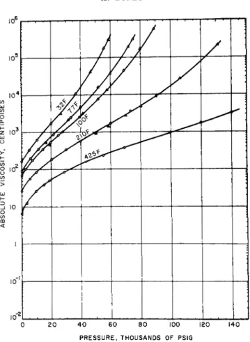
FIG. l c . Viscosity-temperature-pressure relative for polyisobutylene of the same viscosity at 77°F. and 1 atmosphere as the siloxane sample of Fig. l b .
theory, all of these relations should be considered as interpolation rules only.
Inspection of the viscosity-pressure curves shows that for a very large number of oils log ν versus ρ is essentially a straight line while log η versus ρ is slightly curved concave downward in its initial portion. Oils with very flat viscosity-temperature curve tend to exhibit viscosity-pressure curves that are bent concave downward, whereas oils of very steep viscosity-temperature curves exhibit viscosity-pressure curves that are concave upward, and in general it is found that the initial slope of the log- arithmic viscosity-pressure curve is related to the slope of the vis- cosity temperature curve by the simple relation
(d log v/dT-1), = D(d log v/dp)T\p - ο
448 A . B O N D I
ο 10'
10
y <t
:
. . .
2 0 4 0 6 0 8 0 100 120 140 PRESSURE,THOUSANDS OF PSIG
FIG. Id. Viscosity-temperature-pressure relations for perfluorocarbon fluid.
where
D 2.0 X 10⁵ °C. atm. or 5.3 X 10⁶ °F. p.s.i.
for most hydrocarbon oils.1 This relation has foundation in theory, since for simple liquids9
(θ ln η/οΤ~ι)Ρ
(dE/dV)T (3)
(d ln η/ορ)τ
where (dE/dV)T = internal pressure or cohesive energy density, a charac- teristic property of given families of liquids. Hence the relation is valid only for the members of a given family of liquids. The silicones, especially the dimethylsiloxane polymers, occupy a somewhat peculiar position. In keeping with their flat viscosity-temperature curve they exhibit a relatively
9 A. Bondi, Ann. Ν. Y. Acad. Sei. 53, 870 (1951).
R H E O L O G Y OF L U B R I C A T I O N A N D L U B R I C A N T S 449
0.1 J— ι 1 r 1 1 1—ι 1 —
7 0 0 5 5 0 4 0 0 3 0 0 210 100 7 7 3 2 - t. ° F
FIG. 2. Viscosity versus temperature curves of typical commercial lubricants Most of the important range is covered between Curves 1 and 4. The coordinates are log (kinematic viscosity) versus reciprocal absolute temperature. Curve 1, di(2- ethylhexyl) sebacate. Curve 2, light lubricating oil (Sample 24-G of Ref. 1). Curve 3, aviation lubricating oil Navy Symbol 1120. Curve 4, naphthenic oil with 2500 SSU at 100° F . (Sample 38-G of Ref. 1.)
flat initial log ν versus ρ curve, which is concave downward. At about 3000 to 4000 kg./cm.2 pressure the curve inflects and becomes steeply con- cave upward in character, such that a millionfold increase in viscosity is achieved for most silicone oils1 , 10 at less than 8000 kg./cm.2. This odd behavior has been ascribed to the interlocking of the rather regularly shaped molecules. The very similarly shaped polyisobutylenes also ex- hibit a sharply concave upward curvature. However, owing to the lesser compressibility of the hydrocarbons than of the siloxanes, the effect is less extreme. The logarithmic viscosity-temperature and pressure coeffi- cients of high polymer solutions in oils (used as so-called viscosity-index
1 0 P. W. Bridgman, Proc. Am. Acad. Arts Sei. 77, 115 (1948).
450 A . BONDI
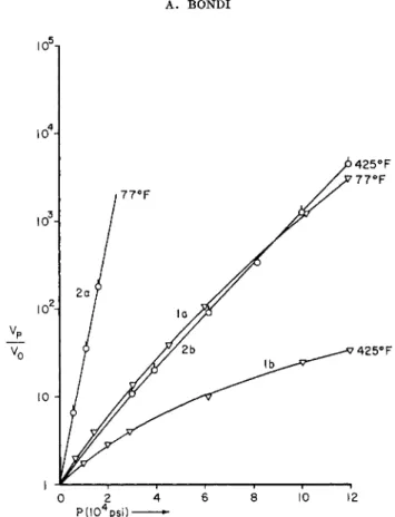
FIG. 3. Relative kinematic viscosity versus pressure curves for the two limiting lubricants of Fig. 2, indicating the large spread of pressure dependence encountered in practice. Curves la and lb, Di(2 ethyl hexyl) sebacate. Curves 2a and 2b, naph- thenic oil (2500 SSU at 100° F.). (Sample 38-G of Ref. 1.) All data from Ref. 1.
TABLE I
FIT OF VISCOSITY DATA ON ASTM VISCOSITY TEMPERATURE CHART (Range Covered: - 4 0 to 350° C.)
Fluids ViSC
°ai%œT
°'$' Straight-line range, °C.Light petroleum oils 10-200 - 2 0 to +150
Heavy petroleum oils 100-2000 0 to +160
Linear diesters 10-50 - 4 0 to +150
Polyethers 20-50 0 to 150
100 100 to 200
Polysiloxanes (methyl) 5-25 - 4 0 to +50
higher - 4 0 to +150
Polysiloxanes (methyl phenyl) all +40 to +150
Fluorocarbons hardly any range
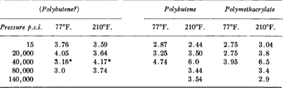
RHEOLOGY O F LUBRICATION AND LUBRICANTS 451 improvers) can to a first approximation be described as those of the oil without the polymer. To the extent that the viscosity increase of such high polymer solutions results from the hydrodynamic interference of the relatively large high polymer particles with the flow, this simple behavior should indeed be expected, viz., the relative viscosity of the polymer solution should be independent of pressure and temperature. Such simple behavior is found for a large number of commercial polymer solutions in oils over wider temperature range and up to a few thousand atmospheres pressure, as is evident from the data of Table II.
The understanding of the specific thickening effect of polymers, expressed as limiting viscosity number
/77/770 — 1 \ =
\ Φ /
Φ-0r^j Ι '// vo \ ι _ In (77/770)
Φ
φ-+0(where 77, 770 = viscosity of solution and solvent, respectively, and φ = volume fraction of solute) has advanced sufficiently that one can predict, at least qualitatively, when the nonideal behavior
ά[η]/αΤ
9E 0 andά\η]/ά
ρτ* 0 should occur. (See Chapter 14 of Vol. I for the theory and the proper- ties of [77].) The most general deviation from ideal behavior results from lack of flexibility of the backbone chain (Table III, Case II). The resulting stiffness makes the random coil and hence [77] large, but as the flexibility must increase with temperature, the coil diameter and therefore [77]
decrease to the theoretical limiting value (corresponding to the random arrangement of a flexible molecule) as the temperature is raised. Owing to the preferred alignment with neighboring solvent molecules, a chain is always stiffer in solution than in vacuo. This effect becomes the more pro-
TABLE II
EFFECT OF PRESSURE AND TEMPERATURE ON THE THICKENING EFFECT OF HIGH POLYMERS IN LUBRICATING OILS
(Expressed in Relative Viscosity ητ =
T/eoiutionAoii)
(Derived from Data of Bradbury et al.1)
{Polybutene?) Polybutene Polymethacrylate Pressure p.s.i. 77°F. 210°F. 77°F. 210°F. 77°F. 210°F.
15 3.76 3.59 2.87 2.44 2.75 3.04
20,000 4.05 3.64 3.25 3.50 2.75 3.8
40,000 3.16* 4.17* 4.74 6.0 3.95 6.5
80,000 3.0 3.74 3.44 3.4
140,000 3.54 2.9
* At 60,000 p.s.i.
4 5 2 A . BONDI T A B L E III
SUMMARY OF RELATIONS BETWEEN POLYMER STRUCTURE AND THE VISCOSITY-TEMPERATURE-PRESSURE FUNCTIONS OF
THEIR SOLUTIONS
Case I Case II Case III Case IV
Chain flexible
+
_+
_Chain stiff —
+
—+
Solubility good good bad (increases with bad (increases with
temp.) temp.)
dM/dT 0 negative positive <S-curve thru 0
dW/dp
0 positive negative <S-curve thru 0 nounced the closer the molecules approach each other. Hence the coil diameter, and [η] for stiff molecules, increase as the pressure is raised.If the chain is flexible but the solubility is poor (case III), the polymer chain may collapse entirely at some low temperature when the polymer comes out of solution. At all temperatures above the precipitation point, the coil is larger than at the collapse and increases and hence [η] increases to the magnitude characteristic of the ideal solution as one raises the temperature. Since such nonideality of a solution usually means that the solution process is accompanied by volume expansion of the system, increasing pressure should decrease the solubility and thereby [77], possibly leading to separation of the system at some high pressure.
Many actual systems are composed of polymer molecules which are at least somewhat stiff and not in perfect solution in the oil at hand. In those cases (case IV) one observes that the [77] versus Τ and the [η] versus ρ curves go through maxima at those temperatures and pressures where the two opposing effects just balance. The few cases for which experimental data are available exhibit the maximum in the ηΓ(~η/η0) versus pressure curve rather well (Table II). All of these general cases have been sum- marized in the table which also includes the "ideal" case of perfect flexi- bility and athermal mixture.
2 . N O N - N E W T O N I A N F L O W OF OILS
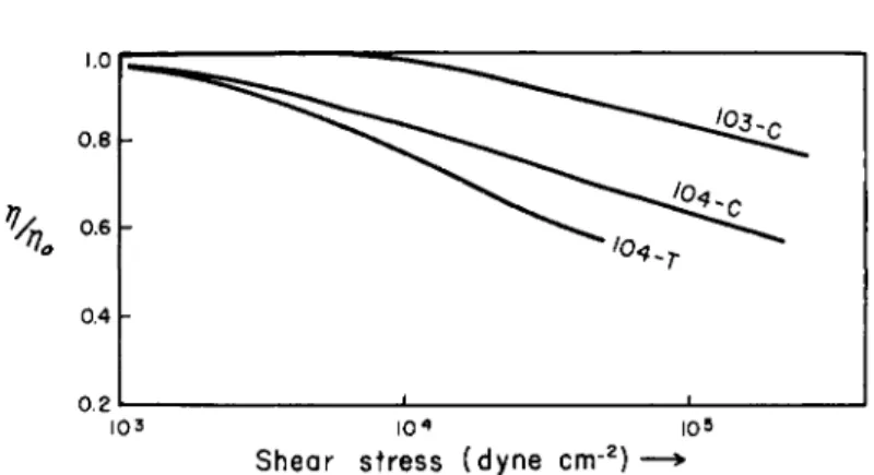
The viscosity of simple liquids is not affected by the imposition of a shear field. Theoretical speculations indicate that at exceedingly high shear stresses there might be a viscosity reduction even for simple liq- uids.1 1, 12 Shear-dependent viscosity is of practical significance only for high polymer solutions. Typical data for such systems are shown in Fig. 4
11 A. Bondi, J. Appl. Phys. 16, 539 (1945).
12 L. Grimberg and A. H. Nissan, Nature 156, 241 (1945)
R H E O L O G Y OF L U B R I C A T I O N A N D L U B R I C A N T S 453
T A B L E I V
EFFECT OF SHEAR STRESS ON THE VISCOSITY OF POLYMER* SOLUTIONS Oil Temperature °C. (l7/Wmint \Αηο/ m i n §
r (η/ηο) mi n||
dynes/cm.2 Ref.
API-103 38-100 0.80 0.72 106
API-104 38-100 0.60 0.44 105 #
Β 38-100 0.77 0.40 2 Χ 105 * *
D 38-100 0.82 0.60 2 Χ 105 * *
* Polymers not identified in published reports.
t Observed relative viscosity at maximum available shear rate of apparatus.
§ Fraction of polymer thickening effect remaining corresponding to (τ//τ7ο)πήη · II Shear stress at which (η/ηο) has the indicated valut, essentially independent of temperature.
# S. J. Needs, Am. Soc. Testing Materials Spec. Tech. Puhl. No. Ill (1951).
** Ε. M. Barber et al.} Anal. Chem. 27, 425 (1955).
and Table IV. The general value of this work is rather small since the polymers used have not been characterized. On the basis of a systematic investigation of the relation between viscosity versus shear-rate behavior and the molecular weight and structure of high polymers and their thermo- dynamic solution parameters one might be placed in a position to predict the behavior of polymer solutions in general.
Existing theory (discussed in Vol. I and Vol. II of this work) pre- dicts in a qualitative way the manner in which molecular structure is related to the reversible shear reduction of the viscosity of high polymer solutions.
However, so far the theory has not been put to sufficiently severe experi- mental tests to consider it as soundly established. In the high shear stress field, especially, under conditions involving cavitation, found in loaded journal bearings and in many oil circulation systems, irreversible reduction
1.0
0.8
0.4
0.2
103 I 04 I 05
Shear s t r e s s (dyne c n r2) — *
FIG. 4. Change of the viscosity of polymer solutions with shear stress.2
454 A . B O N D I
of the viscosity of polymer solutions is experienced owing to the degrada- tion of the polymer. Much of this degradation appears to be oxidative scission facilitated by the mechanical stress to which the system is exposed, and there is evidence that this degradation can be reduced by the addi- tion of suitable oxidation inhibitors.13
The non-Newtonian behavior of two-phase lubricant systems, e.g., waxy systems and greases, will be discussed in Section II.
3. F L O W P R O P E R T I E S A N D H Y D R O D Y N A M I C L U B R I C A T I O N
Elementary hydrodynamic theory of the load-carrying capacity of wedge-shaped fluid films knows only one physical property of fluids, their dynamic viscosity at the operating temperature. In principle nothing has been changed in this in more recent developments. The operating conditions have become so strenuous, however, that the temperature and pressure gradients in the fluid film lead to significant variation of lubricant viscosity throughout the load-carrying area. In order to account quantita- tively for the variation of viscosity and thus the load-carrying capacity of the film under such conditions, data regarding the variation of viscosity with temperature and pressure as well as the physical properties have to be incorporated into the bearing equations, which determine the energy balance in the bearing, namely, the heat capacity and the thermal con- ductivity of the fluid.
The quantitative relationships of the important variables can be sum- marized in very few expressions. The load carrying capacity IF of a wedge- shaped fluid element with constant viscosity η is given (for the journal bearing) by the simple relation
η · u Cho
where u = tangential velocity of journal surface, C = diametrical bearing clearance, D = journal diameter, and ho = minimum thickness of fluid element. The frictional drag in such a system depends on the same variables in the manner
where / = friction coefficient, Κ = numerical constant of the order of unity. As W acquires very high values it becomes necessary to include the change of viscosity with pressure, a = (d \n η/ορ)τ. Then for α ρ < 1, W(p)/W{o) = 1 + ap, where (p) and (o) refer to load-carrying capacity with and without consideration of pressure dependent viscosity, respec-
13 W. A. Zisman and H. A. Pohl, Publication Board No. 78601 (May 1943).
RHEOLOGY OF LUBRICATION AND LUBRICANTS 455 tively. It turns out that even for the largest value of a-p, W(p)/W(o) can never exceed the value 2.3.1 3a
The amount of energy dissipated by viscous drag in the film is often sufficiently large to call for explicit consideration of the temperature coefficient of viscosity β = (d In η/θΤ)Ρ, and of the amount of heat con- vectedby oil out of the film1 3b cp-u and, at high speeds where radial tempera- ture distribution is also important, the amount of heat conducted out of the film into the bearing, characterized by the thermal conductivity λ.
For the case of dominating circumferential temperature gradient, Vogelpohl1 30 obtained the load carrying capacity with temperature-de- pendent viscosity W(T) relative to the temperature independent case
Hence, for this case, of two oils with the same inlet viscosity 77, the one with the higher value of pc/ß will confer a higher load carrying capacity.1 3d Where the radial temperature gradient in the oil film is most significant (i.e., at very high speeds) according to Hagg1 3e
Here, between two oils with the same viscosity 770 at the bearing wall tem- perature the one with a smaller value of β/λ will provide the higher load carrying capacity. In both cases β is the more important property variable since pc and λ vary only over very narrow ranges for the usual organic lubricating fluids.
It has been demonstrated by Cope1 4 , 15 that a finite load can be carried by a fluid film with parallel, not wedge-shaped, boundaries in adiabatic flow because of the pressure gradient established through thermal expansion of the fluid. This so-called thermal wedge effect is restricted to (thrust) bearings with very narrow clearances and the oil properties contribute to the load-carrying capacity proportionally with the ratio 7/β, where 7 = (d In V/dT)P is the thermal expansion coefficient of the oil.
1 3a H. Blok, Ann. Ν. Y. Acad. Sei. 53, No. 4, 779 (1951).
i3b ρ — density, c = specific heat, u — linear circumferential velocity of the oil.
1 30 G. Vogelpohl, VDI Forschungsheft 386 (1937).
1 3d e is a complicated function of the geometry of the film wedge, h$ is the distance at closest approach.
1 3e A. C. Hagg, J. Appl. Mech. 10, A-71 (1944).
14 W. F. Cope, Proc. Roy. Soc. A197, 201 (1949).
15 A. Fogg, Proc. Inst. Mech. Engrs. (London) 155, 49 (1946).
W(0):
456 A . B O N D I
The two primary considerations in bearing design or oil selection are the load-carrying ability and the frictional drag. The first is defined as the load at which under the operating conditions the distance of closest ap- proach of the rubbing surfaces is of the order of at least twice, but pref- erably five times, the average height of the surface irregularities and the frictional drag is a measure of the energy dissipated in the lubricated machine element.
Hydrodynamic separation of the bearing surfaces is sometimes achieved under surprisingly severe conditions. There is increasing evidence that gears with specific loadings as high as 10,000 kg./cm.2 can be separated by a continuous film of oil.16 The conditions governing the formation and maintenance of such films are only now beginning to be understood.17"20
It is rather evident that they are closely related to the mechanical design details of the gear teeth and the infrequency of observation of such types of gear lubrication must be taken as a consequence of the small number of tests which have been carried out with carefully designed and machined gears. The relation of oil properties at such high pressures to hydrodynamic gear lubrication has not yet been studied. The considerable dissipation of energy in the thin layer of lubricant must of necessity lead to the genera- tion of high temperatures as well as high pressures. The evaluation of results is therefore likely to be complex. One may predict on the basis of the pub- lished properties (see Fig. 1) that the dimethyl siloxane fluids would develop such high viscosities21 that the shear stresses in the ''fluid'1 film in the high pressure zone exceed the shear strength of the gear metals.
Consequently shearing may take place in the metal instead of in the lubricant.
Shear stress dependence of viscosity must affect the friction factor of the bearing and its load-carrying capacity. Sharp reduction of viscosity in the region of highest shear rate in the bearing reduces the bearing friction. Such a reduction in bearing friction has indeed been observed with oils containing orientable high polymer molecules.22 The prediction
1 6 V. N. Borsoff et al., Trans. Am. Soc. Mech. Engrs. 73, 687 (1951).
17 A. von Mohrenstein and G. Niemann, private communications.
18 G. Niemann et al. Z. Ver. deut. Ing. 95, 164, 167 (1953); and unpublished reports.
1 9 H. Poritsky, 1st Natl. Symposium Fund. Lubr., Am. Soc. Lubrication Engrs.
(1952).
2 0 C. Weber and G. Niemann, unpublished reports.
2 1 The ability of many, especially polymeric, liquids to support shear waves and exhibit shear stiffness may also play a role in gear lubrication.
2 2 F. W. Ocvirk and G. B. du Bois, Natl. Advisory Comm. Aeronaut, unpublished report.
RHEOLOGY OF LUBRICATION AND LUBRICANTS 457 of the load-carrying capacity of such a non-Newtonian oil film requires more subtle reasoning. The theoretical analysis for the general case of a non-Newtonian fluid predicts a flattened radial pressure distribution around the journal bearing compared with that which is obtained with lubricants of uniform velocity.2 3 , 24 In that case the over-all load-carrying capacity corresponds to the average viscosity in the pressure zone. Experiments with a lime-soap grease at moderate speeds (and shear rates) are in reason- able agreement with both predictions of the theory.25 Experiments with high polymer solutions in high-speed bearings, on the other hand, showed no reduction in load-carrying capacity although the oil viscosity and consequently the bearing friction had been reduced very appreciably by the flow-orientation effects.22 The explanation of this result is still out- standing.
The same materials which impart non-Newtonian viscosity, especially high polymers, also often impart elastic properties to their solutions. Oils with elastic properties are likely to exhibit the Weissenberg effect, i.e., the tendency to flow from regions of high shear stress to one of low shear stress.
As a result such oil blends may be pumped very rapidly out of journal bearings.26
II. Gelled Lubricants 1. LUBRICATING G R E A S E S
Fluid lubricants have numerous advantages over any other form of lubricant. They can be circulated to act as coolant for the bearing, they can carry away the debris of their own decomposition or of extraneous origin and be clarified before their return to the bearing, and so on. But they have one fundamental disadvantage. They have to be retained in the bearing by, sometimes rather elaborate, sealing arrangements. When the cooling of the bearing is not essential, and where a simple bearing design is important, gelled lubricants are often used.
Lubricating greases, as gelled lubricants are generally called, differ therefore from fluid lubricants in the possession of a finite yield stress. The magnitude of the latter is usually just sufficient to prevent loss of lubricant under the operating conditions but not such as to offer significant resistance to the motion of the rubbing surfaces. A Bingham body would be ideally suited for this application. To a first approximation commercial lubricating
2 3 Κ. B. Lawrence, Trans. Am. Soc. Mech. Engrs. 72, 409 (1950).
2 4 H. Umstatter, Kolloid- Ζ. 116, 18 (1950); 118, 37 (1950).
The reader should be warned of the fundamental errors in these papers. See discussion by W. Kochanowsky, Kolloid- Ζ. 142, 32-45 (1955).
2 5 G. Cohn and J. W. Oren, Trans. Am. Soc. Mech. Engrs. 71, 555 (1949).
2 6 G. F. Wood, A. H. Nissan, and F. H. Garner, / . Inst. Petroleum 13, 71 (1947).
458 A . B O N D I
greases have indeed been found to act as Bingham bodies.2 7 , 28 The gel structure of most greases is far too complicated, however, to fall into the exact pattern of a plastic body. The complex gel structure, made up of soap fibers of widely varying dimensions,2 9 , 30 or of bentonite platelets,30
or of sponges of silica gel30 with a wide distribution of particle sizes and bending strengths is hardly likely to exhibit a single well-defined yield stress. One should rather expect successive yielding of structure elements in increasing strength and therefore a pseudoplastic trailing off of the flow curve at low shear stresses.
At very high shear stresses the flow resistance is generally only a small multiple of that offered by the oil itself. It has been argued that at very high shear stresses the cohesion between gel particles makes only a negligible contribution to the flow resistance. One should then be able to consider intrinsic viscosity of the gel agent at high shear stresses as a manifestation of its geometry similar to the case of no interaction, i.e., at infinite dilution.31
In the few cases which have been so examined the geometry of the soap fibers deduced from viscosity was in reasonable agreement with electron microscope evidence. The general applicability of such a method appears questionable, however, since the measurements of gel viscosity at high shear stresses is bedevilled by numerous complications, such as temperature gradients in the steaming system, onset of turbulence, induced by the nonhomogeneous nature of the system. Most important, however, is the shear degradation of the gel particles themselves. Their geometry changes often irreversibly under the influence of the applied shear stress,32 further complicating the interpretation of the flow data.
Owing to the relative proximity of the absolute flow resistance value at high shear stresses to that of the oil, their knowledge is of relatively little practical interest. Of far greater practical importance is the behavior of greases under the influence of low shear stresses, i.e., under near static conditions.
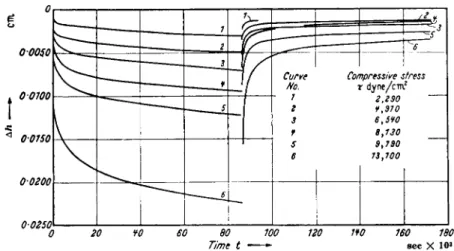
At small deformations, e.g., strains of the order of 10~2, many greases exhibit noticeable elastic deformation with deformation versus time curves very similar to those of other elastic-plastic systems, and illustrated in Fig. 5. Numerous curves like these have been discussed in the litera-
2 7 C. R. Singleterry and Ε. E. Stone, J. Colloid Sei. 6, 171 (1951).
2 8 H. Ε. Mahnke and W. Tabor, Lubrication Engr. 11, 22 (1955).
2 9 A. Bondi et al, Proc. 3rd World Petroleum Congr., Hague Sect. 7, 373 (1951).
3 0 Β. B. Farrington, Ann. Ν. Y. Acad. Sei. 53, 979 (1951).
3 1 G. Β. Moses and I. E. Puddington, Can. J. Research 27B, 616 (1949).
32 R. J. Moore and A. M. Cravath, Ind. Eng. Chem. 43, 2892 (1951).
RHEOLOGY O F LUBRICATION AND LUBRICANTS 459
0 20 ¥0 60 80 100 120 1Ψ0 160 180 Time t sec X 10»
FIG. 5 . Elastic recovery of lubricating greases.33
(Stress released at 9 0 sec)
ture,33"35 but neither their relation to gel structure (or composition) nor to lubrication problems have as yet been systematically explored.
The yield stress of greases is only rarely measured by theoretically acceptable means. Careful direct measurements have brought to light that many greases have not one but two yield values.36 The "first" yield value, generally of the order of a few hundred to about one thousand dynes per square centimeter, is very difficult to measure and probably represents the yield stress of the mixture of gel fiber ends, gel debris, and oil in the boundary layer between grease and the solid surface of the measuring device. The "second" yield value is more readily determined by a wide variety of instruments, such as the parallel plate plastometer, the cone penetrometer,36 the shear blade27 and the Bingham-type or Goodeve-type evaluation of shear rate versus shear stress curves obtained in viscometers of various types.2 7 , 31 Since the yield stress of real bodies is the stress at which measurable permanent deformation takes place during the period of observation, there is great likelihood that the various methods used will differ with respect to what is "measurable" and with respect to the time factor. Considering these inherent differences between instruments the reported agreement27 between different methods on identical samples must
33 J. F . Hutton and J. B. Matthews, Proc. 2nd Intern. Rheol. Congr. Oxford, p.
408 ( 1 9 5 3 ) .
34 E. W. J. Mardles "Selected Government Research Reports, Lubricants and Lubrication." H. M. Stationery Office, London, 1 9 5 2 .
3 5 G. Vinogradov et al., Neftyanoe Khoz. 25, 4 7 ( 1 9 4 7 ) ; 26, 5 2 ( 1 9 4 8 ) .
3 6 J. F . T . Blott and W. B. Bonner, Proc. 1st Intern. Rheol. Congr. Scheveningen Sect. 2 , p. 2 6 5 ( 1 9 4 8 ) .
460 A . B O N D I
be considered as about as good as could be expected. For engineering purposes it is sufficient to determine the yield stress of a grease to ± 3 0 % , and for the more critical identification purposes in the trade one must al- ways adopt standardized methods of measuring procedure.37
The yield stress ry determines the equilibrium height H of a self-sup- porting grease dam according to the relation
H = Ty/pg
where ρ = density of the grease and g = gravitational acceleration (acting in compression on the grease). Since the yield stress in shear is of the same order as the yield stress in compression, one can use the same formula to estimate (crudely) the tangentially acting centrifugal acceleration gc (sub- stituted for g) at which a grease layer of thickness H slides off a rotating surface, if H < 1 mm. and if the grease sticks well on the surface. If the grease does not wet the surface properly, or if oil is exuded in the grease- solid interface, the formula predicts too high a value for gc . Acceleration normal to the grease layer acting in tension leads to a more complicated type of rupture, typical of a Taylor instability, while the yield stress plays only a minor role.
Like other plastic materials lubricating greases exhibit creep at (shear) stresses below the yield stress. This creep flow is non-Newtonian in charac- ter and has been ascribed to the sliding of the bulk of the grease on a layer of oil and gel ends and debris which tends to form at the interface between solid walls and the grease.39
At stresses slightly in excess of the yield stress one often finds for a limited stress range a pseudo-Newtonian flow, which has been ascribed to the sliding of the bulk grease on the oil layer mentioned above but at shear stresses at which the few gel particles make no contribution to the flow properties. As the shear stress is raised far beyond the yield stress the flow resistance decreases in a regular fashion until it approaches the vis- cosity of the oil, as mentioned above. When plotted as log
r/
(ap
Parent) vs.log è nearly straight lines of slopes ^ 0 . 6 to 0.7 are obtained between β ^ 5 and è ^5000 per second.40 Admixture of high polymers, especially to acetylene black gels41 causes the appearance of steplike discontinuities in the η vs. è curves, the origin of which is as yet obscure, but may be
37 See, for instance, ASTM.38
3 8 American Society for Testing Materials Method 3 97-47.
3 9 A. Bondi, Trans. Soc. Rheol. 2 , (1958).
4 0 J. P. Patberg, Sproule, L. W. and J. C. Zimmer, Inst. Spokesman 6, (8, 9, 10, 11) (1942/37); 7 (12) (1944); 9 (15) (1945).
41 Standard Development Co., U. K. Pat No. 607,695 (1948).
RHEOLOGY OF L U B R I C A T I O N A N D L U B R I C A N T S 461 caused by the introduction of strongly elastic components of deforma- tion.
All of the aforementioned properties change with temperature in a complicated manner. Initially, i.e., at temperatures far below the first transition temperature of the soap (if that is the gelling agent), all of them decrease in magnitude exponentially as the temperature is raised. A few degrees below the first transition temperature of the soap, the extent depending upon the chemical composition of the oil, the flow resistance, and the yield stress begin to increase with temperature, pass through a maxi- mum, possibly through a minimum and through additional maxima, depending upon the number of phase transitions of the soap. Finally the viscosity decreases steeply to nearly that of the oil, all of the gelling ability of the soap being lost when the soap dissolves in the oil. Only few data have been published on the temperature function of the flow properties of nonsoap gels. Contrary to first thought these need not be simple func- tions. A flocculate gel structure in vacuo would probably not change its strength over a wide range of temperature. However, in a liquid environ- ment the strength of particle interaction is reduced by the adsorption of the molecules of the liquid. Particle cohesion, in liquids of very similar cohesion energy to that of the particles or their surface may even approach zero. Very strongly adsorbed third components of the liquid may so change the particle surface and thus particle cohesion to mask the inherent prop- erties of the solid. The picture is often further complicated by the very different, but often important effect of a thick (duplex or thicker) layer of a second liquid which is insoluble in the bulk liquid and makes the particles stick together by meniscus formation.42
In pure liquids raising the temperature reduces the lifetime of adsorp- tion, and adhesion of collided particles becomes increasingly frequent.
Hence the gel strength increases as the temperature is raised. Desorption of a surface active component may accentuate the often steep increase in flocculating tendency with temperature. The concurrent reduction in viscosity of the matrix liquid somewhat counteracts the increasing gel strength of the particle network. The resulting net flow resistance and yield stress may therefore present a far-from-simple temperature curve,
the details of which have to be worked out anew for each system. In general one finds the drop in both to be less steep than with many soap greases.
In special cases quite the opposite, namely, initially extremely steep curves can also be obtained which tend to flatten out at the higher tempera- tures.
All of what has been said so far regarding the flow properties of lubricat-
4 2 H. R. Kruyt and F. G. Van Selms, Ree. trav. chim. 62, 415 (1943).
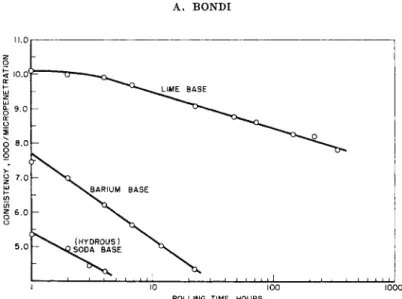
462 A . BONDI 11.0
ζ ο
1000 ROLLING TIME , HOURS
FIG. 6. Shear degradation of lubricating grease.2 9 , 32
ing greases pertains only to the instantaneous values of these properties.
Since the bond strength between the gel particles, whatever their nature might be, is of the order of fcT, the application of shear energy even in the very act of measurement causes irreversible changes in particle configura- tion. If the applied shear stress is great enough or the amount of work done on the system large enough, actual particle comminution or in some cases particle agglomeration may be induced. Upon return to rest the changed system will then acquire a new configuration. The result is that all properties of greases are strongly time-dependent and can be thoroughly changed by continued shearing.
In the case of soap grease the shear degradation is primarily associated with the comminution of the particles.32 Typical degradation curves are shown in Fig. 6. The mechanism of consistency recovery upon return to rest of the sj^stem is far less understood. It is often called thixotropy43 but is only rarely truly characterized by this designation since the original definition of thixotropy (by Freundlich) implies a reversible process. The fact that very frequently the consistency of the recovered system after severe shearing is far higher than that of the unsheared sample demonstrates the inapplicability of the term thixotropy to these phenomena. Much further work is required to clarify the kinetics of particle bonding re- sponsible for the hardening.
Attempts have been made to describe the flow properties of greases in terms of continuum mechanics or as superposition phenomena of different
4 3 L. W. MacLennan and G. H. Smith, Am. Soc. Testing Materials Bull. No. 152, 71 (1948).
RHEOLOGY O F LUBRICATION A N D LUBRICANTS 463 types of bonds which have to be broken.44 After what has been described above, such approaches, while courageous, can hardly be expected to provide new insight into the flow processes even if they provide an accept- able formal description of the instantaneous flow curves. Recent simul- taneous electrical and mechanical measurements have further shown that the flow of greases is rather likely to proceed in the manner of fruit jams, namely, by relative motion of elastically deforming gel lumps.4 5 , 46 On simple consideration of the process of yielding of crystalline solids, which always proceeds through discontinuous flow glide plane production in the crystal lattice, it becomes clear that a body with finite yield stress or yield stress range can only flow if comminuted into smaller macroscopic parts, the size of which depends upon the applied shear stress. A theory describing grease flow on this basis has not yet been developed.
2. F L O W PROPERTIES O F F R O Z E N O I L S
Oils increase in viscosity as the temperature is lowered by two distinc- tive mechanisms. One type of oil simply turns into a transparent glass, i.e., the viscosity increases smoothly and reaches values which prohibit its use as a lubricant. Other oils, may crystallize partially. The precipitated wax crystals form a coherent network and the oil stiffens before the vis- cosity of the fluid components has reached very high values. The flow properties of the waxy two-phase mixture do not differ significantly from those of the lubricating grease discussed above. Owing to the weakness of the wax crystals irreversible shear degradation is brought about by relatively small shearing forces.
The flow diagram of frozen waxy oils is therefore rather less well defined than that of grease, its position often depending upon the shear stress at the start of the experiment. In addition, owing to the weakness of the structure the flow resistance becomes effectively Newtonian at relatively low shear stress. The maximum shear stress that can be applied to such systems is limited by the consideration that any appreciable energy dissipation will lead to sufficient temperature rise to melt part of the solid structure. In experiments with continued shearing such partial melting of the structure has been shown to occur.47 Continued working at sufficiently low shearing stresses to exclude appreciable temperature rise the shear degradation of the waxy component of many oils has been found to depend only upon the total work input.48
44 R. E. Powell and H. Eyring, Nature 154, 427 (1944).
4 5 A. Bondi and C. J. Penther, J. Phys. Chem. 57, 72 (1953).
4 6 A. Bondi, Proc. 2nd Intern. Rheol. Congr. Oxford p. 274 (1953).
47 S. P. Jones, Jr., and T. K. Tyson, / . Colloid Sei. 7, 272, (1952).
48 G. Gavlin, Ε. A. Swire, and S. P. Jones, Jr., Ind. Eng. Chem. 45, 2327 (1953).
464 A . BONDI
The yield stress of frozen oils is of the order of 100 to 1000 dynes/cm.2 in the temperature range in which one can handle the oil successfully in pipelines (v.i.).2,49 By use of suitable agents, so-called "pour point depres- sants," the yield stress of frozen oils can be reduced appreciably.2' 50 Independent of oil composition, the logarithm of the yield stress of frozen oils has been reported to be generally proportional to the inverse absolute temperature at reasonable distances from the "pour point" of the oil.50 The thermal and the mechanical history of the sample must be carefully reproduced to obtain useful information related to the problem that is to be investigated. A common but not very useful measure of the low tem- perature behaviors of oils is the temperature at which, under carefully specified conditions, an oil column of small height ceases to flow under the influence of gravity. This temperature is called the pour point. Many oils with relatively weak wax structure will easily flow below this temperature under the application of but mild shearing stresses.
The formation of a coherent wax structure can be prevented by a wide variety of compounds, all of which are characterized by the possession of paraffin chains and some noncrystallizing groups in their molecular struc- ture.51 Since the energy of adsorption on a hydrocarbon surface out of a hydrocarbon solution must be quite small, it is believed that the paraffin chains of these compounds, the pour point depressants, somehow interact, even if only in a two-dimensional way, with the paraffin chains of the wax crystals. The relatively great specificity of interaction between pour-point depressants and certain wax types is in accord with such a view.51 These agents do not only reduce the yield strength of the wax structure and the temperature at which the oil will stiffen but also reduce the flow resistance at moderate shear stresses by very large factors.2
3. M O T I O N OF G E L L E D LUBRICANTS T H R O U G H P I P E S
Gelled lubricants, both frozen oils and greases, have to be moved through pipes. In order to appreciate the problem of doing so one must realize that the available shear stresses in refinery pumping systems, especially the suction lines, range between 100 and 1000 dynes/cm.2, while in grease- distributing system they may be of the order of 10,000 to 50,000 dynes/cm.2. Obviously in either case the yield stress of the lubricant has to be lower than the available shear stress in order to permit flow to occur. Once flow has set in, the resistance to motion decreases, owing to the shear breakdown of the gel structure.
The prediction of the grease flow rate through pipes can be carried out
49 F. Gill and R. J. Russell, Ind. Eng. Chem. 46, 1264 (1954).
6 0 K. S. Ramaya, Conf. on Viscosity of Liquids and Colloidal Soins. U.S.S.R. 2 , 179 (1944).
6 1 R. A. Ruehrwein, Proc. 3rd World Petroleum Congr. Hague Sect. 7, 423 (1951).
RHEOLOGY OF LUBRICATION AND LUBRICANTS 465 in various degrees of sophistication. The simplest approach is to assume that grease is a Bingham body with a well defined yield stress ry and a mobility m. The integrated form of the Bingham differential equation for pipe flow, the Buckingham equation then predicts the flow rate as:
where Π = τ„/Δρ and D = pipe diameter. The agreement between the pipe flow predicted by means of this equation from data obtained with small capillaries or Couette viscometers and actual performance is only moderately good.5 2a
Very much better results are obtained through use of the empirical Ostwald relation
where rw = shear stress at the wall, e = shear rate. For pipe flow, this relation takes the form
where a = average velocity of grease in the pipe. The exponent η is a measure of the deviation from Newtonian flow, where η = 1. For lubricating greases, η and k are constant only over ranges of about one to two decades in e. In the ranges of practical interest in pipe flow (é = 5 to 100 sec.- 1), η for greases ranges generally between 0.1 and 0.4. Since according to Metzner and Reed5 2b the velocity profile is essentially that of plug flow for η = 0.2, the utility of the Ostwald relation is consistent with Mahnke's
(28) visual observation of plug flow for lubricating greases.
From an engineering point of view it is useful to know that pipe flow of greases can be predicted from the usual Fanning friction factor / versus ΝRe graph if one defines the Reynolds number as
where ρ = density of grease. In the laminar flow region, then,
Hence the pressure drop in grease flow is very much less sensitive to pipe diameter than it is with Newtonian fluids; or conversely one may increase
5 2a L. C. Brunstrum and R. H. Leet, Lubrication Eng. 12, 316 (1956).
5 2b A. B. Metzner and J. C. Reed, Α. I. Ch. Ε. Journal 1, 434 (1955).
rw oc ên when TW > ry
DAp/^L = k (Su/D) η
466 A . B O N D I
the grease flow rate q through a given pipe many fold without experiencing large increases in pressure drop if η is small.
A large range of r and ê can be covered with a single set of constants when the Powell-Eyring (44) equation
is employed.5 2a The experimental determination of the constants 77, Ay and Β is somewhat awkward, and a graphical method5 20 has been developed to facilitate the process. It has not yet been established whether the constants of this equation really have the physical significance originally attached to them in their theoretical development.
None of the previous equations considered the (thixotropic) breakdown which the grease suffers as it moves through the pipe. An experimental correction for this loss in consistency with time of stress application has been proposed.5 2d It is based on the empirical observation that
where C and m are constants, m < 1, which can be determined in suitable laboratory experiments. The pressure drop in a pipe is smaller than that cal- culated in the absence of this effect by a factor of the order of \/C{u/L)l+m A peculiar phenomenon is the delayed and incomplete pressure trans- mission through lines filled with gelled oils, such that even under static conditions the full pressure is not transmitted to the end of a pipe.49 This phenomenon makes the use of pressure taps very ill advised, even on viscometer bodies, and membranes flush with the wall should be used Very viscous oils move through pipes with a distorted velocity profile even in the absence of any structural anomalies if the viscous energy dis- sipation generates enough heat to create a significant temperature gradient in the oil. The complicated mathematical problem of flow with energy dissipation, heat transfer and the usual steep temperature dependence of viscosity has been solved by von Schlippe.5 2f The calculations show that an oil flowing at given velocity through a cooled pipe can be cooled only to a certain minimum temperature at which heat generation and heat
5 2c Ε. B. Christiansen, N. W. Ryan, and W. E. Stevens, Α. I. Ch. Ε. Journal 1, 544 (1955).
6 2d J. W. Wilson and G. H. Smith, Ind. Eng. Chem. 41, 770 (1948).
5 2e P. G. Exline and J. R. Aikens, U.S. Patent 2,503,660.
C 2f B. von Schlippe, Bericht No. 9, Deutsche Versuchsanstalt fur Luftfahrt, Köln, 1956.
M Ν. Marusov, U.S. Patent 2,503,676.
r = e-C (L/u) m
instead.1 52e, 53
R H E O L O G Y OF L U B R I C A T I O N A N D L U B R I C A N T S 4 6 7
flow to the outside just balance. As a consequence of this result, one finds that the pressure drop can be much smaller (by as much as one or two orders of magnitude) than one would have predicted without consideration of the internal heating effect.
4 . H Y D R O D Y N A M I C L U B R I C A T I O N W I T H G E L L E D L U B R I C A N T S
Theoretical calculations of the load-carrying capacity and the frictional resistance of macroscopic films of gelled lubricants have been presented recently. The case of journal-bearing lubrication was worked out for a pseudoplastic lubricant utilizing its empirically determined curve of apparent viscosity versus shear rate.23 The theory predicts, in agreement with experiment, that the pressure distribution around a bearing is rather flatter with a pseudoplastic body than it is with Newtonian fluids. The other published theories start from the assumption that the lubricant can be described adequately as a Bingham body with yield stress ry and mobility m. (The inverse of m is often called "plastic viscosity.") The calculations, carried out for a slider bearing,54 for the "squeeze-film,"55 and for the equivalent of the hydrostatic bearing,56 indicate an appreciable gain in load-carrying capacity over that obtainable with a Newtonian fluid of equal mobility, especially at low velocities. In fact, the theory predicts the possession of a finite load-carrying capacity, proportional to ry/h (where h = bearing clearance) at zero velocity.
The latter result should not be taken too literally, however, because lubricating greases creep at a sufficiently high rate even at loads of the order of half their short-time yield stress that permanent separation of bearing surfaces at zero velocity should not be expected.
III. Flow Phenomena in Boundary Lubrication
Boundary lubrication always involves the simultaneous deformation of the solid bearing metal and of the lubricant layer. The finite wear rate coupled with a friction coefficient much lower than is obtained for the rub- bing of metallic solids in direct contact testify to the importance of the simultaneous incidence of both phenomena.
1. F R I C T I O N OF S O L I D S U R F A C E S
The mechanics of the friction of solid surfaces involves deformation and destruction of the rubbing solids on a macroscopic scale. The work
6 4 A. A. Milne, Proc. 2nd Intern. Rheol. Congr. Oxford p. 427 (1953).
6 6 F. Osterle and E. A. Saibel, Lubrication Eng. 11, 187 (1955).
6 6 F. Osterle and E. A. Saibel, Am. Soc. Mech. Engrs.-Am. Soc. Lubrication Engrs.
Meeting, October 1955, Paper 55 LUB-6.
468 A . BONDI
of Holm5 and of the Bowden school58 has amply demonstrated the defor- mation in depth which accompanies the rubbing effects on solid surfaces.
The surfaces of solids are never smooth on a microscopic scale. Asperities, the size and size distribution of which is determined by the finishing treat- ment which the surface received, are always contacted first as one solid is lowered on another. The "true" area of contact is thus only a small fraction of the geometrical contact area. By electrical methods it has been shown that over a range of contact pressures the deformation of the as- perities follows a law such that the true area of contact is directly propor- tional to the load, if both solids are metals.5 7 , 58
The specific load at the contact points is always sufficient to cause plastic deformation of the asperities involved. The plastic flow, i.e., the sliding of crystal grains past each other along linear slide paths, is of itself occasionally the source of additional surface irregularity which prevents disengagement of the asperities as they are moved past each other and may lead to their breakage in the cross section just beyond their work-hardened area.59 Very often, if not most often, the pressure is sufficient to cause
"pressure welding" of the asperity junctions, and subsequent "plucking out" of parts of the weaker asperities.57 The friction of metals is probably very often just due to these local adhesions and represents the force neces- sary to shear the small junctions.
Analysis of the foregoing model led to the conclusion that the friction force F = As, where s = shear strength of the weaker of the junctions and A = true area of contact. The latter depends on the load W according to the simple law A = W/Pm , where Pm = yield pressure of the softer of the two solids. Hence the friction coefficient μ of unlubricated rubbing solids can be expressed in terms of the flow properties of the softer of the two solids in contact as
μ = F/W
=
s/PmMore detailed consideration of the life cycle of a single junction in plastic deformation60 shows that for the usual surface roughness, where the angle of ascent of the hills is of the order of 10°, the initial shear stress on the junction is Si ^ 1.2 Pm , the normal stress Pj ^ 2Pm , regardless of the hardness of the metal. For strong junctions which fracture when the normal load is at its maximum, the minimum value of μ is Si/P ^ 1/2.6 ^ 0.4. For a junction which survives to a symmetrical shape, μ ^ 1. For very ductile materials where the junction survives even when W becomes
57 R. Holm, "Electrical Contacts." Stockholm, 1946.
68 F. P. Bowden and D. Tabor, "Friction and Lubrication of Solids", Oxford Univ.
Press, London and New York, 1951.
69 L. M. Feng, J. Appl. Phys. 23, 1011 (1952).
6 0 A. P. Green, Proc. Roy Soc. A228, 191 (1955).
RHEOLOGY OF LUBRICATION AND LUBRICANTS 469 tensile, μ > 1. Superposition of elastic straining of the bulk material behind the junction raises Si and reduces P i , thus increasing μ. It is ap- parent from this analysis that brittle substances, fracturing readily in tensile deformation, should exhibit lower friction coefficients than ductile substances, if both sliders form strong junctions.60
The macroscopic theory of solid friction by Bowden58 and by Holm57
leads to useful results only as long as the solid surfaces are covered by a nonmetallic layer—it need only be one atom thick—to prevent gross welding on contact.
If the metal surfaces are absolutely clean, contact leads to instantaneous cementation of the surfaces, the junctions acquiring the bulk shear strength of the solid, and friction coefficients as high as 100+ are observed, if both surfaces are made of the same metal.61 The usually known friction co- efficients of the order of unity or less are generally associated with the presence of oxide layers of low shear strength on the surface. The presence of the oxide layers and their behaviors during sliding, etc., is easily dem- onstrated by electrical measurements.58, 6 2' 63 If the flow properties of oxide and substrate metal are similar, as for AI, Cd, and Zn, mechanical disrup- tion of the oxide layer has little effect on friction. If the oxide has a greater shear strength than the metal, the friction coefficient drops as the oxide film breaks down, i.e., as the load is raised beyond a certain point, whereas with copper, where the oxide film exhibits the lower friction coefficient, the breakage of the oxide film is accompanied by a sharp rise in the friction coefficient, as is shown by the η versus W curves of Fig. 7. The harder the metal substrate of a given oxide, the lower the depth of penetration into it, hence the lower the coefficient of friction.63 Chromium is so far the only known substance the oxide and metal of which are both so hard that no breakage of the oxide layer occurs over the entire ^106-fold load range studied, and consequently the friction coefficient likewise does not change over the same load range.
The ultimate-strength properties of macroscopic solids depend on the number of flaws (crystal imperfections, dislocations, and cracks) in the stressed region. Very small samples or very small regions of large samples are therefore much stronger than predicted from measurements on large samples. These strength anomalies have been observed by Smekal64 and Hunt65 and are likely to become important for surface asperities of the order of one micron or less. Such small roughnesses occur rarely in lubrica-
61 A. T. Gwathmey, Ann. N.Y. Acad. Sei. 53, 987 (1951); Proc. Roy Soc. A212, 464 (1952).
62 W. E. Campbell, Lubrication Eng. 9, 195 (1953).
6 3 R. Wilson, Proc. Roy. Soc. A212, 450 (1952).
64 A. Smekal, Kolloid-Z. 131, 106 (1953).
6 5 F. V. Hunt, / . Appl. Phys. 26, 850 (1955).