LIGHT S O U R C E S *
4 . GLOW DISCHARGE
A glow discharge (the common form of discharge at low p r e s - sures) is a self-sustaining phenomenon, that is, one which persists after the external source of ionization has been withdrawn. A nonself-sustaining discharge may become one if the number of electrons and ions produced in it is larger than or equal to the number of ions leaving the discharge space. It is the development of electron avalanches that is responsible for the creation of ions in a discharge. Thus, the electrons in the discharge gap ionize atoms upon collision with the latter. This in turn releases other electrons, which again ionize other atoms, until an electron ava- lanche results. The number of electrons drifting toward the anode increases with the distance from the cathode. The potential dif- ference at which a nonself-sustaining discharge becomes self- sustaining is termed the firing potential. It has been shown ex- perimentally (Fig. 10) that the firing potential depends on the product pd, where ρ is pressure and d the distance separating the
•See also general handbooks on gas discharges [21, 22, 105, 107, 171-174], 31
electrodes in a discharge tube. The curves in the plot show minima, reflecting a twofold effect. On the one hand, an increase in either the pressure or the size of the discharge gap increases the number of ionizing encounters, and hence facilitates the initiation of a discharge. On the other hand, the mean free path of an electron decreases with pressure so that the electron accumulates l e s s energy between collisions. Thus the probability of ionization by collision diminishes, and the initiation of a discharge becomes more difficult. The firing potential of a discharge depends on the type of gas filling the tube and the electrode material. Minute traces of gaseous impurities materially alter the value of the firing potential.
Voltage, V 1600 1400
600
200
-J 1 1 1 « 1_ _l I I I I 1 I
2 4 6 8 10 12 14 16 16 20 22 24 26 26 30 pd FIG. 10. Firing potential vs. pd.
In a glow discharge the cathode remains cold, while a marked cathode potential drop obtains due to the special nature of the distribution of space charges. In glow discharges, lower external resistance produces a higher current density. At some density the potential at either end of the discharge tube begins to drop, the flashover characteristic droops, and the glow discharge becomes an arc discharge, which is characterized by a high current density [ 1 7 4 - 1 7 6 ] .
Under the conditions of a glow discharge the basic processes resulting in a current flow through the gas are ionization by colli- sions and the release of electrons, some of which are knocked out from the cathode by positive ions while others are ejected as a result of the photoelectric effect associated with the radiation produced by the discharge itself [153, 1 7 7 ] .
According to a recent concept advanced by Neu [178], any deficiency in the number of charged particles in a discharge is compensated for by fast atoms, which cause additional ionization.
The fast atoms themselves result from charge transfer.
To the observer, a glow discharge appears to be divided into several regions: 1) a thin dark layer, the Aston dark space, in the immediate vicinity of the cathode; 2) a luminous layer called the first cathode glow; 3) the Crookes (or Hiltorf) dark space; 4) the negative glow region, which is extremely bright in the section near the cathode but grows l e s s and l e s s luminous with distance from it; 5) the Faraday dark space; 6) the positive column extend- ing from the anode to the Faraday dark space; and 7) the anode region of the discharge.
The length of the positive column depends on the distance between the electrodes. When the electrodes are moved toward each other, the cathode sections of the discharge remain unchanged, while the positive column is " c o m p r e s s e d " and, at a certain inter- electrode distance, completely eliminated. When the cathode is displaced in a direction perpendicular to the tube axis, the cathode fall sections of the discharge move with it, but the positive column remains in place, filling all of the remaining space up to the anode.
It follows that the charged particles move in an oriented manner in the cathode area and at random in the positive column. A s a result, the walls exert an appreciable effect only on the column, but not on the cathode fall.
If the intereleetrode distance is shorter than the sum of the cathode sections of the discharge (but all conditions remain as before), then the voltage necessary to initiate the discharge must be considerably higher (i.e., the discharge is difficult to start).
The processes occurring in a glow discharge will be under- stood better if the reader is acquainted with the details of each of the discharge sections. It is clear from the above that the p r o c e s s e s sustaining the discharge occur at the cathode. These are the only processes necessary for sustaining the discharge.
Most of the potential drop between the electrodes occurs in the Crookes dark space, where the electric field strength is maxi- mum. It is the field at the cathode which causes the electrons to gather momentum and acquire sufficient energy for exciting and ionizing the g a s . Ionization produces a large quantity of free electrons and positive ions in the Crookes dark space, but since the velocity of the ions is much lower than that of the e l e c - trons, the result is a positive space charge in that section. The dark space ions then impinge on the cathode, knocking out further electrons, the final result of the ionization and ion impact being an electron avalanche. To a first approximation, the size of the Crookes space varies inversely with the pressure; this is b e - cause each electron must create enough ions to knock out one electron from the cathode (if that does not happen, the dis- charge dies out). This means that the size of the Crookes space decreases with pressure: higher pressures produce a greater number of collisions, i.e., more ions per unit length of the dark space.
The cathode drop9 a basic parameter of the Crookes dark space, is the potential difference between the boundaries of this space. The cathode gradient depends on both the surface ionization
and volume ionization coefficients,* and is considerably reduced by the presence of impurities in the g a s .
The cathode drop is independent of the pressure or the current up to the point where the entire cathode surface becomes covered by the glow. Beyond this point it increases with the current and current density (abnormal cathode drop). It follows that Ohm's law does not apply to a glow discharge. A drop in potential differ- ence with increasing current (a falling current-voltage charac- teristic) has in fact been recorded for currents large enough to heat up the cathode.
An abnormal cathode drop is associated with cathode sputter- ing, a phenomenon present, although to a l e s s e r degree, in the case of a normal cathode fall. The sputtering is strongly affected by both the electrode material and the gas filling the discharge tube. Sputtering is more pronounced in heavy gases than in light ones, and is stronger for metals of low chemical activity than for highly active ones. In addition, the degree of sputtering is an inverse function of the heat of sublimation of the metal. Detailed studies of this process have shown that it is intensified at lower pressures and larger currents. Cathode sputtering is always accompanied by gas adsorption in the atomized particles, whereby inert gases are adsorbed l e s s intensively than are the chemically active ones. The gas adsorbed by both the vaporized metal and the electrodes themselves can be partially liberated by heating.
The gas adsorption processes in an electrodeless discharge differ from those in a discharge between internal electrodes [179].
In the first case all the adsorbed gas can be liberated by heating the walls to 3 0 0 ° C . In the second case the adsorption never leads
* The surface ionization coefficient indicates the number of electrons ejected from the cathode due to the impact of a positive ion. The volume ionization coefficient indi- cates the number of electrons and ions produced by a single electron as it travels a distance of 1 cm on the path from the anode to the cathode.
to saturation, even when inert gases are involved. Hundreds of monomolecular layers are adsorbed but not liberated on heating.
It was shown [175] that gas adsorption is determined by the rate of evaporation of the metal and the surface potential at which metal deposits.
In recent experiments, gas adsorption in a discharge has been studied by radioisotope techniques [180]. Adsorption tests using Kr85 disclosed no radioactivity at the anode, but the cathode proved to be radioactive even at a considerable depth (several thousand monoatomic layers). The experiments were carried out in a neon-argon mixture containing 0.0001% Kr85 . The discharge tube was operated for 24 hours, the discharge current and potential being maintained at 30 m A and 150 V .
The interaction of gases with the glass and electrodes is described in various communications [ 1 8 1 - 1 8 4 ] .
Cathode sputtering has often proved a source of e r r o r s in the spectral analysis of gas mixtures, since the rate of gas adsorption by the metal film formed on sputtering varies for different g a s e s . As a consequence, the composition of the gas mixture may change in the course of the discharge, inevitably affecting the spectral analysis data. Because the gases may be adsorbed and liberated by the electrodes and the sputtered material, the experimenter
should forgo, wherever possible, the use of internal electrodes in spectral analysis. Alternatively, he may work with s m a l l e r cur- rents and higher pressures in order to reduce the cathode- sputtering effect. The effect of gas adsorption will likewise be reduced if the test is concluded in a stream of gas flowing through the discharge gap.
Adjacent to the Crookes dark space is a luminous region (cathode glow) characterized by a very slight potential gradient.
In the sector facing the anode the gradient may even be negative;
i.e., the potential may decrease toward the anode. Two factors appear to be involved in this effect. First, due to intensive ioniza- tion, the anode end of the glow region contains a large number of free, relatively slow electrons. Second, some of the ionizing electrons in the negative glow region retain a considerable fraction of their energy. The combined action of both groups of electrons can produce the negative gradient. A s the distance from the cathode increases, the electron energy diminishes and the glow becomes l e s s bright. Spectroscopic studies have shown that the lines corresponding to lower excitation energies are located in that region of the cathode glow which is c l o s e r to the cathode [148].
That region contains many spark lines and, when a mixture of gases is present in the tube, the excited lines are those correspond- ing to the gas with the larger ionization and excitation energies.
This is explained by the presence of electrons which have accu- mulated high energies (of the order of tens of electron volts) in passage through the cathode fall. The electron concentration in the cathode glow region is much higher than in the other sections of the discharge.
The Faraday dark space is located next to the cathode glow region. It emits a rather faint light because the potential gradient in this sector is low and the electrons are thus unable to accumu- late energy to replace that lost on passage through the glow region.
The electron concentration in the Faraday space, especially in the section nearer the cathode, is as high as in the positive column.
In the vicinity of the anode there is another dark space, which merges into the anode glow region. The anode potential drop, amounting to several tens of volts, is not a fixed component of the discharge. It may vanish when the electrons impinge on the anode, that is, when the anode is located inside the glow region produced by the cathode.
The positive column, which extends through the entire space between the anode and the cathode fall regions, is the most i m - portant light source in the glow discharge. The basic function of the positive column is transmission of the current through the g a s . The potential gradient over the length of the column becomes stabilized at a fixed level and, for a constant current density, may be taken to increase inversely with the tube diameter. In a narrow tube the positive ions and electrons reach the walls in l e s s time than they do in a wide tube. The result is a higher recombination rate, which must be compensated for by increasing the number of excitation events which in turn involves a higher longitudinal field gradient.
In a narrow tube a major influence is the transverse field gen- erated by negative charges on the walls, which are stored up as the wall is bombarded by electrons drifting toward it. The c r o s s - field effect produces a curvature in the equipotential surfaces; the latter become convex, protruding toward the cathode. A negative charge on the walls causes ions to drift toward them [143, 1 8 5 ] .
At high pressures and large currents, a pinching (contraction) of the discharge is noted in the tube: the discharge is compressed into a fairly narrow luminous " r o d " along the tube axis. The effect stems from the difference in the gas density between the wall and axial areas. Because of the high heat transfer rate from the walls to the external air, the gas layer adjacent to the walls has a lower temperature, and therefore a higher density, than the gas in the axial region. The lower gas density along the axis, in turn, produces a longer mean free path for the electrons, which facilitates the operation of the discharge, reducing the longitudinal potential gradient in the tube. After its initial establishment, the discharge then narrows further, because the gas core along the axis heats up progressively, and thus the gas density drops off
further. The theory of the pinch effect is far from complete at the present time.
Pinching of the discharge may also be caused by a longitudinal magnetic field [ 1 8 6 - 1 8 8 ] . In that c a s e , the discharge appears to be "flowing" through a narrow "capillary": the latter has no solid walls upon which ion recombination could take place. In many c a s e s a longitudinal magnetic field is a more convenient means of compressing the discharge than is the use of fine capil- l a r i e s . The effect of such a field on the electron temperature and concentration is negligible [189]. A transverse magnetic field, on the other hand, conspicuously increases the brightness of the discharge.
Compression of the discharge promotes excitation of the ion lines. While all lines are intensified, the degree of intensification varies from level to level, being unequal even for lines emitted by adjacent levels [190]. If impurities are present, the positive column may become striated, with alternating light and dark strata. No definitive theory has thus far been offered to account for discharge striation, although a few attempts have been made [ 1 9 1 - 1 9 3 ] .
Electrophoresis
Luminescence of the gas mixture in a DC glow discharge is associated with electrophoresis, an effect which shows up in the increased concentration of the readily ionized constituent (as well as of the component with greater atomic weight) at the cathode.
Electrophoretic phenomena have been explored in numerous ex- perimental studies [103, 104, 1 9 4 - 2 0 5 ] .
Two theories have been proposed to explain the separation of a binary gas mixture [204]. One of these (the "ion" theory) attributes the separation to a positive ion transport toward the
cathode. The stream consists mainly of the component with the lower ionization potential since the number of ions of the other component in the gap discharge is very small [108]. The net result is a greater concentration of the easily ionized constituent at the cathode.
The other ("momentum") theory is based on the assumption that a certain momentum, directed toward the anode, is imparted to the atoms of the gas by bombarding electrons. The transferred momentum is an inverse function of the molecular weight of the gas; consequently, the lighter gas will tend to accumulate at the anode.
The experimental studies of Matveyeva [203] suggest that the separation is due to the difference of ionization potentials rather than in the difference of atomic weights. This is confirmed by the observation that no separation occurs if the concentration of the difficult-to-ionize component in the mixture is low. The fact that the separation depends on the concentration of the readily ionizable component cannot be explained by the momentum theory, but c o m e s out easily from the ion transport theory. The degree of separation increases with the length of the tube and the current.
Up to a point, it also increases with pressure and time allowed for separation; however, saturation is reached at a certain time and a certain pressure. This occurs when the gas transport due to ion drift becomes compensated by back-diffusion resulting from the concentration gradient. Thus it takes some time before a concentration equilibrium can become established at the electrodes.
Electrophoresis may be used in spectral analysis; it can serve to enrich the gas mixture and to free it of traces of impurities [198, 2 0 2 ] .
The gas in the positive column is a quasi-neutral plasma; i.e., the concentration of electrons equals that of positive ions at any
given point of the space. The ion concentration (i.e., the degree of ionization) need not be very high. The temperature correspond- ing to the average electron velocity is several tens of thousands of degrees. On the other hand, the gas itself is at a much lower temperature because the rate of energy exchange between the electrons and the atoms is low. In a glow discharge the high elec- tron temperature produces excitation of lines thatcannotbe excited in an arc or a spark at atmospheric pressure. The metastable atoms are of considerable importance in glow discharges (see Section 1).
The electron velocity distribution in the positive column gen- erally follows Maxwell's law (see Section 2), although marked deviations from that pattern are occasionally noted under certain conditions.
Whereas the excited lines seen in the spectra of the positive column at moderate current densities are predominantly those of atoms, the glow spectra do display some ion lines as well. This is due to the fact that some faster electrons are present in the glow discharge [206], as well as to the fact that the number of en- counters between the electrons and ions is larger than elsewhere because of the high ion concentrations.
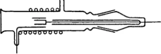
The hollow cathode
A special form of the glow discharge is that proceeding in a hollow cathode (Fig. 11), and is widely used in spectroscopy. Its application to spectroscopy is due to Paschen [207]. In this a r - rangement, at certain pressures and currents the glow is confined within the cathode, whereby the entire cathode potential drop takes place in a very thin layer forming at the internal walls of the cathode tube. This permits high electron velocities even at rela- tively high pressures because the electrons bounce back and forth
between the electrode walls, and are able to produce an intense luminescence in the g a s e s . Both ionic and atomic lines are excited inside a hollow cathode. With gaseous mixtures, the use of a hollow cathode results in simultaneous excitation of atomic lines whose excitation potentials are very much different. This ability to excite varying levels simultaneously is the basis for the use of
hollow-cathode discharge tubes in spectral analysis.
A detailed description of various designs of discharge tubes with hollow cathodes is given in [ 2 0 8 - 2 1 0 ] . The atomic glow inside a hollow cathode was studied spectroscopically by Frisch et ale [146, 147]. Some data on electron velocity distributions were reported by Veith [211]. A number of experimental studies on the mechanism of discharge in a hollow cathode provided a basis for a tentative discharge theory [153, 155, 212, 2 1 3 ] . It was shown [213] that the specific nature of a discharge in a hollow cathode is related to the high ion concentration and the high velocities of the ions striking the cathode walls. The hollow- cathode discharge closely resembles an abnormal glow discharge.
The discharge induced in the gap by a rapidly alternating electromagnetic field is called a. high-frequency (or radiofrequency) discharge. Under these conditions, the charged particles are unable to follow the rapid changes in the field direction. This results in a phase difference between the electric field and particle
FIG. 11. Paschen's tube with a hollow cathode.
5. HIGH-FREQUENCY DISCHARGE
velocity, a difference proportional to the m a s s of the moving particles. For practical purposes, the ions existing in a stable high-frequency discharge may be treated as motionless. On the other hand, the motion of the electrons in an AC field, is deter- mined by the ratio of the electromagnetic field frequency ω to the frequency of collision vc on which the moving electrons experi- ence [172].
For moderate current densities, the effect of the magnetic field may be considered negligible. Moreover, if ω ^> vc on the encounters of electrons with gas particles during a single field cycle may likewise be ignored. An oscillatory motion caused by the field is thus superposed on the random thermal motion of the electrons. The magnitude and direction of the translational c o m - ponent of velocity depend on the phase of the AC field at the moment when the electron begins to m o v e . If the field phase is ~ or - ^ , the field causes the electron to perform harmonic oscilla- tions about a certain equilibrium position. The translational component of the velocity is maximum when the field phase equals 0 or π.. The particular case where ω ^ > vCoii is achieved only with high field frequency and low gas p r e s s u r e . In such c a s e s very little energy is required to maintain the discharge.
In the case where ω < να οι ι , which takes place at high gas pressures and low field frequencies, electron drift sets in, due to the large number of collisions between the electrons and the gas particles taking place during a single field cycle. The conditions of the discharge approximate those which establish themselves in a DC discharge. The quantity of energy required for sustaining the discharge is very high.
In most instances, however, the actual conditions determining the motion of the electrons do not correspond to either of the two extreme c a s e s . A s in the first c a s e , an oscillatory motion b e c o m e s
superposed on the translational motion of the electron, but the effect of impacts of electrons on the gas particles during one field cycle can no longer be neglected. It is also not possible to ignore the changes occurring in the electric field, or the velocity dis- tribution in the moving electrons in the time interval between two successive collisions.
The theory of high-frequency discharges was developed by Holstein [214], Margenau [215] and Hartman [216] on the basis of Boltzmann's gas-kinetic equation. W e shall consider here only high-frequency discharges at reduced pressure generated by con- tinuous oscillation since it is this type of discharge that is used in spectroscopy and spectral analysis.
The range of frequencies used for spectrum excitation is extremely broad. Most studies, both early and recent, have used frequencies in the range of several kilocycles to a few hundred megacycles. Only in the past decade and a half have bands in the range 2000 M c / s to 50,000 M c / s become popular.
In establishing the theory of the high-frequency discharge it is important to know whether the high-frequency discharge p o s s e s s e s some specific characteristics that distinguish it from other types of discharges and whether the frequency is a discharge parameter equal in importance to the current and the pressure. If the dis- charge technique is to be applied effectively in spectral analysis, it is important to know the effect of the frequency on the electric parameters of the discharge. It is even more important to know how the variation of frequency affects the excitation of components of a mixture.
The type of coupling between the oscillator circuit and the discharge gap depends on the exciting frequency range. At f r e - quencies below 2500 M c / s , the power is supplied via external or internal electrodes (except in the case of an electrodeless ring
discharge). When working with frequencies above 2500 M c / s , the discharge tube is installed in a waveguide. The type of coupling determines the distinctive characteristics of a high-frequency discharge, since it determines the amount of power that can be fed to the discharge gap. Conventionally, two types of high-frequency discharge are distinguished at low pressures: glow discharge and ring discharge [22, 1 7 2 ] .
High-frequency glow discharge
This is generated in a gap connected to a high-frequency circuit through internal or external electrodes. The external observer will see several clearly defined regions of the discharge. The positive column is located in the section midway between the two electrodes, both of which act as cathodes, each carrying the full complement of regions of the cathode fall. The oscillatory motion of the electrons in the discharge tube causes intensive ionization, eliminating the necessity of electron ejection from the cathode;
i.e., the electrode processes are of no vital significance. The regions of a high-frequency discharge located near the electrodes are identical with the cathode fall regions of a DC glow discharge [217, 2 1 8 ] . Lodge and Stewart [218] studied the distribution of deposits on the discharge tube walls for the case of a high frequency discharge generated through external electrodes. The experiments revealed the development of a process analogous to the cathode sputtering present in a DC glow discharge.*
In discharges using external electrodes, the function of the cathode is performed by a section of the discharge tube located inside the outer electrode. The strong radial field inside the
•The mechanism of sputtering of internal electrodes in high frequency discharge was studied by Levitskiy [219], using the range of 1-70 Mc/s and atmospheres of argon and hydrogen.
electrode causes an ionic bombardment of the ug l a s s cathode'9 [220]. In consequence, a kind of "hollow cathode" is formed inside the electrode. The assumption s e e m s all the more plausible if we consider the differences in spectra obtained inside the electrode space and in its vicinity [221]. Thus, inside the electrode one o b - serves luminescence of those nitrogen bands that require very high energies for excitation. A l s o , it is possible to excite the He II spark line of λ = 4686 Â (excitationpotential 75.6 eV) inside a high- frequency "hollow cathode." The above shows that basically there is not much difference between the high-frequency and the usual type of glow dis chargee
The parameters of the positive column of high-frequency and DC glow discharges were compared in a s e r i e s of studies. The firing potential of the high-frequency discharge is considerably smaller than that of the DC system, and varies with the frequency [222, 2 2 3 ] . The effect of the walls on the firing potential s e e m s especially important [224, 2 2 5 ] .
Beck [226] compared a high-frequency discharge (wavelength 5 m ) with a DC discharge (potential 1200 V ) , using a discharge tube with a hot cathode and a nickel anode. A 5 0 - m A current was employed in both c a s e s . In both c a s e s , Hg lines ( λ = 5461 Â ) of equal intensity were obtained. The ratio of intensities of all lines of the mercury spectrum and the Hg line with λ = 5461 Â proved to be identical at three different pressures ( 1 0_ 3, 7·10~3 and 0.3 m m Hg). The electron temperature values obtained by Beck via probe measurements for high-frequency and DC discharges were identical at high p r e s s u r e s , and only at low pressures was a slight divergence noted.
The probe measurement data reported by Beck are consistent with those obtained in later studies [87, 227, 228] in which the electric parameters ( Te and ne ) of high-frequency and DC discharges
were compared. Thus, the comparison of DC and high-frequency ( 5 - M c / s ) discharges in helium, neon and argon was made by Dzerpetov and Pateyuk [227], while Avramov and Dzerpetov [87]
studied it in helium and neon. The values of Te and ne obtained in the two types of discharges were identical. Similar results were obtained when working with a high-frequency ( 1 7 0 - M c / s ) discharge at pressures in the range 0 . 2 6 - 1 m m Hg [228].
The effect of the frequency (over the range of 0 . 7 - 7 0 M c / s ) on the electron concentration for a high-frequency discharge in mercury was studied by Levitskiy and Shashurin [ 8 6 ] . When the frequency was varied from 0.7 to 20 M c / s the value of ne was reduced by a factor of 4; on further increase to 70 M c / s , this value increased by a factor of 2 . 5 .
Bhatt [229] and Nöller [230] noted that the spectra in high- frequency discharges do not differ from those obtained at other frequencies. In Nailer's experiments, the effect of a high-frequency discharge in helium, observed over the medium-wavelength range ( λ = 7 5 m ) , was compared with that of a short-wave discharge ( λ = 30 c m ) . The author concluded that the ratio of intensities of spectral lines does not vary with the frequency. However, Noller's conclusion is not well documented since the lines he selected for comparison are not particularly sensitive to variations in discharge conditions.
W e ourselves tested the effect of variation of the exciting f r e - quency on the ratio of spectral line intensities in gas mixtures whose constituents differed sharply in their ionization potentials.
W e used a mixture of 5% argon in helium in a 2 - m m I.D. capillary at a pressure of 0.5 m m Hg, varying the wavelength from 9 - 9 2 m.
W e saw no evidence of any changes in spectra which could be associated with the frequency variation, in contrast to the results reported in many other communications [ 2 3 1 - 2 3 4 ] . However, in
varying the frequency it is quite difficult to ensure constancy of all the other discharge parameters. W e cannot be certain, there- fore, that the differences in spectra observed by the other authors were directly related to the frequency of the exciting s y s t e m .
The differences in the behavior of electrical parameters of high-frequency and DC discharges become apparent only at high frequencies and relatively low gas p r e s s u r e s .
It would thus appear that in c a s e s where ω <C vc o ll the high- frequency discharge does not differ from the DC discharge, and no effect of frequency on the spectra is noted over an extremely wide range of frequencies and p r e s s u r e s . Nonetheless, there is a clear advantage in using a high-frequency discharge for spectral analysis. It eliminates the need for metal electrodes inside the discharge tube, thus reducing gas adsorption during the discharge and eliminating the possibility of a chemical reaction with the electrode metals. Moreover, a high-frequency discharge can be started at very low pressures where the excitation of gases with high ionization potentials is most favorable.
It was shown [235-237] that there exist two types of high- frequency discharge ("weak" and "strong") that differ in their optical and electric characteristics. The transition from one type of discharge to the other can be discontinuous. The pressure range in which both kinds of discharge can exist varies with the nature of the gas and the diameter of the discharge tube. In a
"weak" discharge it is the lines with the higher excitation po- tentials which are more intense; the opposite is true for "strong"
discharges. A l s o , the concentration of excited atoms is also higher in the case of strong discharges. The observed optical differences are due to the difference in electron concentrations;
however, the electron temperatures appear to be identical. The electrical parameters of weak and strong discharges were compared
in a special study [236]. The existence of two kinds of discharge was verified by Levitskiy [ 2 2 3 ] , who tested the effect of pressure on the firing potential of a high-frequency discharge in argon and hydrogen, using the transitional frequency range. The curves of pressure v s . firing potential displayed an abrupt r i s e separating the two types of discharge. Both forms may also occur when a longitudinal magnetic field is superposed on a high-frequency discharge [223, 2 3 5 , 2 3 6 ] . In this c a s e , a weak discharge may transform to a strong one, with the latter then sustained regardless of whether the magnetic field is present or not.
In recent years the superhigh-frequency (SHF) discharge has been steadily gaining in popularity [238, 2 3 9 ] . This range is gen- erally understood to include frequencies between 10,000 and 50,000 M c / s * (the millimeter, or ultrashort wave, range). In the superfrequency band (more exactly, at its lower boundary) the oscillation amplitude of the electrons becomes smaller than the dimensions of the discharge tube. This determines the two dis- tinctive features of a superfrequency discharge: 1) the discharge is carried exclusively by electrons; and 2) electrode and the tube wall processes are inconsequential.
Vashman et al. [241] noted significant changes in the discharge conditions upon transition from 6 M c / s to 3000 M c / s . In a helium- argon mixture, the employment of superhigh frequencies caused a better than twofold increase in the ratio of intensity of the 5 8 7 6 - Â helium line to various argon lines. This impies that the sensitivity of spectral analysis for the difficult-to-excite c o m p o - nent of the mixture should increase when the decimeter range is employed.
*The special features of the superfrequency discharge are occasionally observed even at lower frequencies, that is, the centimeter range [240],
The superfrequency discharge conditions differ drastically from those in other types of discharge [238]. A striking charac- teristic is the extremely high electric-field component [242]. An increase in the general brightness of the discharge with frequency was observed in numerous experiments [240, 243, 2 4 4 ] . The effect of the oscillator frequency on gas adsorption was studied by Meggers and Westfall [240]. Thus, an increase in frequency from 30 M c / s to 90 M c / s resulted in a nearly three hundredfold d e - crease in adsorption of gases by mercury, and in the frequency region above 100 M c / s , no perceptible gas adsorption was r e - corded.
Extensive spectroscopic studies of the high-frequency glow discharges have been made [99, 126, 2 4 5 - 2 4 7 ] . Cabannes [246]
demonstrated that in a large-diameter discharge tube, the spark lines are excited only near the axis—an indication of a nonuniform column c r o s s section. Harrison [126] observed a strong reabsorp- tion in hydrogen lines even when the hydrogen constituted only 1%
of the mixture. Studies of the high-frequency discharge in neon [99] disclosed that reabsorption may involve even the lines ter- minating at the 2/?53p levels. All the observed facts point to a high concentration of excited atoms in high-frequency discharges.
Ring discharge
A high-frequency discharge may be produced in the form of a ring generated in a discharge tube placed directly in an alternating magnetic field. The process is similar to induction of a current in a solid metal. The theory of the electrodeless discharge was worked out by Thomson [248] and Mierdel [249]. A schematic diagram of Thomson's circuit for the excitation of a ring discharge is shown in Fig. 1 2 . This basic arrangement has been used by all later experimenters with only minor modifications. While the first
spectroscopic study of glow discharge luminescence dates back to 1913 [250], it was Thomson who described the essential charac- teristics of the ring discharge. Thus, the ring discharge can exist
on starting a discharge in a toroid were conducted by Davydov [252], while Birkkhoff [253] investigated the electrical p r o c e s s e s involved in a high-frequency ring discharge.
The power consumption in this discharge is determined by the length and capacitance of the discharge gap. In general (although there are some exceptions) [254], the distribution of excitation energies through the c r o s s - s e c t i o n of the ring is nonuniform, with spectral lines of higher excitation energy being concentrated in the outer layers while those of lower energies tend to stay in the inner layers. The ring discharge has thus proved useful in c l a s - sification of spectra [ 2 5 5 - 2 5 8 ] , since it allows the simultaneous observation of lines produced by both normal and ionized atoms.
If the image of a luminous ring is projected onto the slit of a stigmatic spectrograph then the spectrogram will show both long (arc) and short (spark) lines. A s the length of the discharge gap is increased the spark lines, produced by single-charge ions, become longer and, in addition, short lines representing doubly- ionized atoms are observed. The possibility of simultaneously observing spectral lines with different excitation energies suggests that the ring discharge may prove extremely valuable in spectral analysis, especially analysis of g a s e s , where the basic difficulty has been to produce simultaneous luminescence of two components of a mixture which differ sharply in their ionization potentials.
FIG. 12. Thomson's spark generator.
only in an extremely narrow range of p r e s s u r e s . The effects of frequency and pressure on the conditions required for producing a ring discharge in various gases were studied by Strauss [251]. Experiments
However, a spark generator based on the Thomson circuit can hardly be expected to maintain constant discharge conditions, especially since long discharge gaps ( 7 - 1 0 m m ) are required in order to obtain large excitation energies. The sine wave vacuum tube oscillator s e e m s preferable in this respect. However, its power must be very high. Thus pulse oscillators are preferred [51, 259] because these are capable of generating pulses of very high power while the average power of the output is rather moder- ate. In addition, the vacuum tube oscillators are capable of main- taining constant conditions in the discharge.
In one arrangement [260], pulses are generated at low voltage and high capacitance. An electrodeless tube filled with gases or vapors at a pressure of a few hundreths of a millimeter is placed in the center of a coil through which pass high-frequency currents.
At pulses with power lower than 10 kW only the arc lines are excited. The average discharge power is about 500 kW. Spark lines appear only when the pulse voltage is increased. On the negative side, when a pulse oscillator is used to generate high- frequency discharges (either the ring or glow type), the field strength required for starting the discharge must be very high, the strength varying inversely with the pulse duration τ .
6. PULSE DISCHARGES IN TUBES WITH INTERNAL ELECTRODES
The pulse discharge is characterized by high current densities and a high degree of ionization. Thus, when a pulse discharge is produced by discharging a condenser (fed by a source of DC c u r - rent) through the gap, one can obtain spectra of doubly and triply ionized atoms, even though the aver age power of the discharge is low.
The circuit diagram of a pulse generator is shown in Fig. 1 3 . It is seen from the figure that the condenser is charged until a certain
T^LTLTLT C = 2 - lOOjiFZ:
potential difference is reached and then discharges through the discharge gap. Circuits of this type have been used by many e x - perimenters [ 2 6 1 - 2 7 2 ] . To increase the limiting potential to which
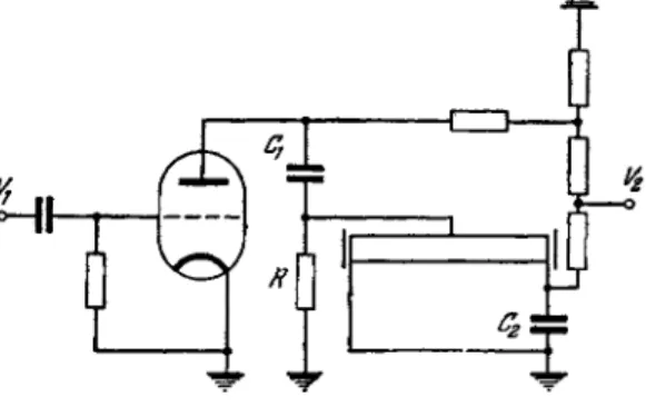
the condenser can be charged, a sparkover gap is connected in s e r i e s with the discharge tube. Thus, the potential a c r o s s the tube can be higher than the firing potential. In- stead of the spark gap, the firing can be controlled by means of a simple electronic circuit, shown in Fig. 14 [265]. The pulse duration may thus be varied from 10"6 to 10~3 seconds. The discharge power is determined by the condenser capacity and the potential difference at the condenser at discharge. The electric properties of the pulse discharge are discussed in detail by Laporte [ 2 7 2 ] .
FIG. 13. Pulse oscillator with a spark gap.
FIG. 14. Circuit for control of pulse discharge.
Ci = 0.01 JiF; C2 = 0.56 }iF; R = 100 ohms; Vi = 150-200 V; V2 = 25-50 kV.
The pulse discharge mode can be either oscillatory or aperiodic, depending on the capacitance, self-inductance and resistance of the circuit. The conditions under which the oscillatory mode changes to aperiodic are given by the general relationship for a conventional
4L
oscillatory circuit: if C>-^- the discharge b e c o m e s aperiodic.
It follows that an increase of the circuit capacitance, at a given self-inductance and resistance, may result in transition from the oscillatory to the aperiodic mode.
The value of the peak current r i s e s with increasing capacitance until saturation is reached. A further increase in capacitance will not produce a higher peak current but will increase both the pulse duration and its energy. The maximum current density, even when the average density is relatively low, may be as high as several thousand amperes per square centimeter. To obtain large current maxima it is necessary to reduce both the inductance and the effective resistance of the circuit. Pulse condensers with a low self-inductance are employed most advantageously in this c a s e . Tubes producing very bright discharges have constant resistances amounting to several ohms [264, 2 6 8 ] .
At low pressures the brightness of the discharge is consider- ably lower. Intense pulses of short duration are obtained at low capacitances and high voltages. The composition and the energy of the discharge radiation depend on the nature and pressure of the gas, the tube diameter, and the electric parameters of the d i s - charge. The radiant background, for example, is l e s s intense in narrow than in large-diameter tubes, and its intensity is higher in tubes filled with a heavy rather than a light g a s . There is practically no background when the discharge tube is filled with helium.
The pulse discharge parameters were studied in inert gases by VuPfson and Bogdanov [263, 2 6 4 ] . Their circuit consisted of a condenser connected in s e r i e s with a thyratron and a discharge tube. They have shown that the pulse discharge, in contrast to the arc and spark, is characterized by a very large potential drop and therefore a large potential gradient in the positive column (which may reach several hundred, or even thousand, volts per
centimeter). The high-power discharge results in complete ioniza- tion of the g a s . Only a few atoms are ionized immediately after the breakdown, when the energy transmitted to the gas is still s m a l l . However, the number of ionized atoms grows as the energy stored in the condenser is dissipated in the discharge gap. Intense ionization is accompanied by a drop in electron temperature and a simultaneous r i s e in the atomic and ionic temperatures. By the end of the pulse the electron and atom temperatures are equal.
Following the discharge, a recombination process sets in, and energy is dissipated by convection l o s s e s and because of the heat conduction by the gas.
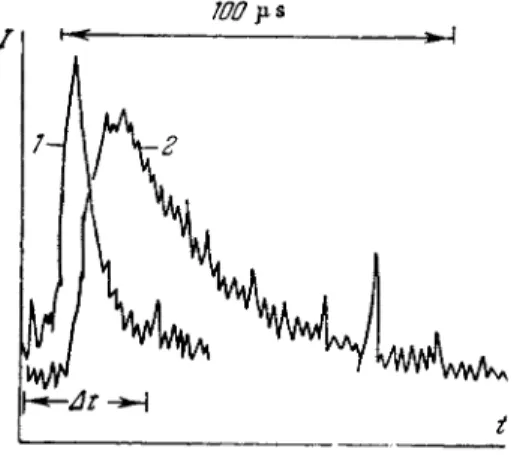
A pulse discharge, unlike an arc, excites s o m e ionic lines along with the atomic lines. Studies of pulse discharges by the time-resolved spectrum method [263] showed that spark lines are excited earlier than arc lines. This method is described in detail in the literature [273, 2 7 5 ] . Figure 15 shows a time-resolved spectrum of radiation f r o m a krypton tube (length 50 c m ; diameter 10 mm; pressure ρ = 5 m m Hg) [263].
100μs
J
t
FIG. 15. Time-resolved radiation spectrum from a krypton tube. 1—Kr II, 4292.94 Â; 2—Kr I,
4273.96 Â.
*The time-resolved spark spectra show an analogous behavior [275],
So rapid is the "heating" of the gas that the curves in the time resolution of the spectrum record only its "cooling." * If the
"heating" proceeded more slowly, a plasma warmup period would also be recorded, and the arc lines would reach maximum intensity before the spark lines, since they require l e s s excitation energy.
As seen from Fig. 15, the spark spectrum is the first to be excited.
Its peak intensity lags the current maximum, and is reached when most of the power has been dissipated in the discharge gap. The arc spectrum, on the other hand, does not appear until recombina- tion has set in. This occurs only after the end of current passage;
therefore, the intensity peak of an arc line is shifted to the right of the spark line peak.
High-power pulses can also be obtained in a tube in which the breakdown of the discharge gap is achieved by means of a third electrode [261, 2 6 9 ] . The charged condenser is connected to the discharge tube electrodes, but the firing potential of the discharge is much higher than the potential existing a c r o s s the condenser.
Hence the breakdown does not occur until a potential is established at the third electrode by means of a special transformer. It is also possible to eliminate the third electrode by placing the tube inside the inductance coil of a high-frequency circuit [270]. An alternative, simpler method is to connect a wire touching the glass tube to a Tesla transformer [271],
Thus the pulse discharge studies show that we are dealing here with a highly ionized plasma. The instantaneous discharge power reaches enormously high levels. This creates conditions which facilitate the excitation even of gases with very high ionization potentials.