Snaking Trailers
Hanna Zsofia Horvath1 and Denes Takacs2
1 Department of Applied Mechanics, Budapest University of Technology and Economics, Budapest, Hungary,
horvath.hanna.zsofia@gmail.com,
2 MTA-BME Research Group on Dynamics of Machines and Vehicles, Budapest, Hungary,
takacs@mm.bme.hu
Abstract. A mechanical model is constructed for the stability analysis of two-wheeled suitcases and trailers. The main assumptions of the model are summarized and the linearised equations of motion are presented.
The linear stability of the rectilinear motion is investigated, critical pa- rameter values are determined for the different level of complexity of the model. Numerical simulations are used to verify the applicability of the model for the nonlinear analysis of the rocking motion of trailers.
Keywords: two-wheeled suitcase, trailer, non-smooth system, non-holonomic system
1 Introduction
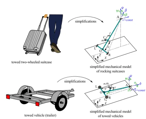
The instability of towed vehicles (e.g. trailers, semi-trailers) is a relevant safety risk in road transport. Namely, under certain conditions (badly chosen load con- ditions and speed), a snaking motion may appear (see [1, 2]), which can even lead to the rocking motion of the trailer when it jumps from one of its wheels to the other. As a final result, the linear instability of the rectilinear motion of the trailer may cause the roll-over of the vehicle. This phenomenon can also be observed in case of a towed two-wheeled suitcase (see [3–6]), moreover similar mechanical models can be composed for the investigations of the stability be- haviour. The analogies of the problems and the mechanical models are illustrated in Fig. 1.
In our former study, we used the mechanical model of the rocking suitcase shown in the right top panel of Fig. 1 to analyse the linear stability and the basis of attraction of the rectilinear motion by means of numerical simulations and experiments (see [7]). The most exciting problem in the analysis of the mechan- ical model arises in the fact that governing equations of the mechanical model are non-smooth since different equations of motion describe the motion states of the suitcase (namely, when both wheels are on the ground, left or right wheel is on the ground, none of the wheels is on the ground). In addition, a kinematic constraint can be defined for the rolling wheels having point-like contact with
Fig. 1.Illustration of the analogy between rocking suitcases and snaking trailers with respect to their mechanical models.
the ground. The switching between the motion states is a complex task since switching appears when one of the wheels has an impact with the ground or when one of the wheels leaves the ground. Nevertheless, by implementing the mechanical model with its intricate non-smooth properties in a simulation code, one can investigate the effects of the initial conditions (e.g. initial tilting angle) and the different parameters (e.g. towing speedv, geometrical parameterseand f).
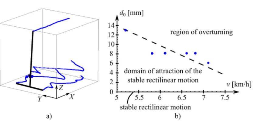
Of course, similar investigation can be done experimentally. A model-based experimental setup was also built and placed on a conveyor belt in [7]. The towed suitcase was perturbed at its left wheel by placing a cylindrical obstacle (with diameter d0) onto to conveyor belt, and the motion of the suitcase was recorded by a motion capturing system using retro-reflective markers (see the left panel of Fig. 2). The detected basis of attraction of the rectilinear motion and its dependence on the towing speed can be seen in the right panel Fig. 2, where blue dots refer to the measurement points and dashed line illustrates the boundary of the basis of attraction. Both the numerical and experimental results confirmed that the attractive domain is smaller for larger speeds. In this study, we modify the mechanical model of the rocking suitcase to make it suitable for the analysis of the stability problem of trailers. In order to do this, the elasticities of the tyres and the wheel suspension system are taken into account.
Although these modifications increase the degrees of freedom and the number of
Fig. 2.a) The trajectories of the retro-reflective markers attached to the suitcase at left and the right wheels, the centre of mass and the towing point, b) basis of attraction of the rectilinear motion identified by experiments.
the parameters of the model, the mechanical model turns to be holonomic and the motion can be described uniquely with the same generalized coordinates independently from the actual motion state. After the short summary of the derivation of the equations of motion, the linear stability of the rectilinear motion is shown in the paper and numerical simulations are carried out to verify the applicability of the constructed mechanical model for the investigation of the nonlinear dynamics of rocking trailers.
2 Mechanical model of snaking trailers
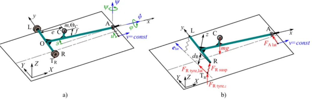
The mechanical model of snaking trailers can be seen on the left panel of Fig. 3.
The motion of the trailer can be described with the yaw angleψ, the pitch angle ϑ, the roll angleϕand the lateral displacementuof the joint at point A. Thus, the system has n= 4 degrees of freedom (DoF), the vector of the generalized coordinates is
q=
ψ ϑ ϕ uT
. (1)
The towing length and the track width of the trailer are denoted by l and 2b, respectively. The position of the centre of mass C can be described with parameters eandf. The overall stiffness and damping of the wheel suspension and tyres are denoted by k and c, while the lateral stiffness and damping at point A areklandcl. The equations of motion can be derived with the Lagrange equation of the second kind:
d dt
∂T
∂q˙k
− ∂T
∂qk
=Qk, k= 1. . . n , (2) whereT is the kinetic energy,qk is thekth generalized coordinate andQk is the kth component of the generalized force. The kinetic energy is calculated as
T = 1
2mvC2+1
2ωTΘCω, (3)
ΘC= 0 ΘC,y 0 0 0 ΘC,z
(x,y,z)
. (5)
The generalized force can be obtained from the virtual power:
δP =G·δvC+FRtyre·δvTR+FRsusp·δvR+FLtyre·δvTL+FLsusp·δvL+FAlat·δvA, (6) whereGis the gravitational force,FRtyre andFLtyre represent the forces acting on the tyres at points TR and TL. FRsusp and FLsusp are the forces acting on the chassis of the trailer at points R and L due to the elastic deformation of the suspensions.FAlat is the lateral force acting at point A. These forces are shown in the right panel of Fig. 3.
O
A C f
m, C
TR
Z Y X
L
R
v=const
e u
a) y x
Z X Y
L C
R
A mg
y x z
FR tyre,lat
TR elat
b) dR
v=const
FR tyre,z
FA lat
FR susp
Fig. 3.a) The mechanical model, b) active forces acting on trailer.
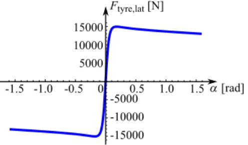
The tyre forces can be calculated with the help of the Magic Formula of Pacejka (see [8]):
Ftyre,lat(α, Fz) =FzDsin (Carctan (Bα−E(Bα−arctan(Bα)))), (7) whereB, C, D, Eare the tyre parameters andFzis the vertical load on the tyre.
The tyre force characteristics can be seen in Fig. 4. The side slip angle of the right wheel can be calculated as
αR=−arctan
vTR·elat vTR−(vTR·elat)elat
, (8)
where unit vectorelatrefers to the lateral direction of the trailer projected to the ground. The side slip angle of the left wheel can be calculated similarly. The
15000 10000 5000
-15000 -10000 -5000 0
Ftyre,lat [N]
0.5 1.0 1.5 -0.5
-1.0 -1.5
Fig. 4. The characteristics of the tyre forces in case of Fz = 15 000 N. The factors:
B = 10 (stiffness factor), C = 1.9 (shape factor), D = 1 (peak factor), E = 0.97 (curvature factor).
force originated in the wheel suspension acts on the trailer in thezdirection, its magnitude is
FR susp= ((LR,0−dR)k+ (vTR,z−vR,z)c)·H(LR,0−dR)
·H((LR,0−dR)k+ (vTR,z−vR,z)c) (9) for the right wheel, where the Heaviside-function H(x) = (1 + tanh (x/ε))/2 with the smoothing parameterεis used to make the system to be smooth. The parameter LR,0 is the free length of the spring while dR is the actual length of the spring (see panel (b) in Fig. 3). The force originated in the left wheel suspension can be calculated similarly.
3 Linear stability analysis
The rectilinear motion of the trailer corresponds to:ψ(t)≡ψ0= 0,ϑ(t)≡ ϑ0= 0, ϕ(t)≡ ϕ0 = 0,u(t)≡u0 = 0 in case of the spring free length LR,0 ≡LL,0 = h+mg(l−e)/(2kl). The linearised equation of motion can be written as
M¨q+Cq˙ +Kq=0, (10) where the mass matrix is
M=
m(e−l)2+ΘC,z 0 mf(l−e) m(e−l)
0 mf2+m(e−l)2+ΘC,y 0 0
mf(l−e) 0 mf2+ΘC,x −mf
m(e−l) 0 −mf m
,
(11) the damping matrix is
C=
BCDmgl(l−e)
v 0 BCDmgh(e−l)
v
BCDmg(e−l) v
0 2cl2 0 0
BCDmgh(e−l)
v 0 2b2clv+BCDmghlv 2(l−e) BCDmgh(e−l) lv BCDmg(e−l)
v 0 BCDmgh(e−l)
lv
cllv+BCDmgh2(l−e) lv
(12)
3.1 The pitch motion of the trailer
The equation of motion of the separable subsystem is a second order ordinary differential equation, from which the critical value of the stiffness k can be ex- pressed:
kcr= mgf
2l2 . (14)
This critical value corresponds to static loss of stability, namely, the trailer over- turns about the lateral axis for k < kcr.
3.2 The yaw and roll motion of the trailer
The equations of motion of the coupled subsystem consist of three, second order ordinary differential equations. By using the trial solution
q=Aeλt (15)
with the characteristic rootλ, the characteristic equation becomes det λ2M+λC+K
= 0. (16)
The stability of the rectilinear motion can be investigated by Routh–Hurwitz criteria. Unfortunately, no closed form expression can be given for the critical parameter values in general case. But for kl → ∞(i.e. when the joint at A is laterally rigid), the system simplifies to an= 3 DoF system and critical stiffness values can be determined for the undamped (c= 0) case:
kcr,1=mg(l(f+h)−eh)
2b2l , (17)
and
kcr,2 = mgl2(l(e−l)ΘC,x+f hΘC,z))
2b2l2(me2h−mel(f+ 2h) +mf l2+h(ΘC,z+ml2))−
−mgBCDh(e−l) me2h2−2mehl(f+h) +h2ΘC,z+ml2(f+h)2+ΘC,xl2 2b2l2(me2h−mel(f+ 2h) +mf l2+h(ΘC,z+l2m)) .
(18)
Static stability loss occurs ifk < kcr,1, namely the trailer falls over. Dynamic loss of stability happens ifkcr,1 < k < kcr,2, and the rectilinear motion is stable for kcr,2< k. These critical values can be also identified by the numerical calculation of the characteristic roots, see panel (a) of Fig. 5, where the real part of the rightmost characteristic root is plotted versus the stiffness.
Of course, the linear stability of original four degree-of-freedom mechanical model can also be investigated numerically. Panel (b) of Fig. 5 shows the real part of the rightmost characteristic root versus the towing speed v. For a cer- tain velocity range (approx. between 10 and 26 m/s), the rectilinear motion is unstable.
10 20 30 40 50
-0.1 -0.2 -0.3
0 v[m/s]
vcr,2 vcr,1
b) a)
20 40 60 80 100 120
0 k[kN/m]
0.02 0.04 0.06 0.08 0.10
kcr,1 kcr,2
Fig. 5.The real part of the rightmost characteristic root of the linearised system. a) Critical spring stiffness values for the 3 DoF model, b) unstable speed range in case of the 4 DoF model. Parameter values:l= 3 m,b= 0.8 m,e= 1 m,f= 1 m,h= 0.5 m, m= 3000 kg,k= 60000 N/m,c= 6000 Ns/m,B = 10,C= 1.9,D= 1,E= 0.97, a) kl→ ∞, b)kl= 10000 N/m,cl= 100 Ns/m.
4 Simulation
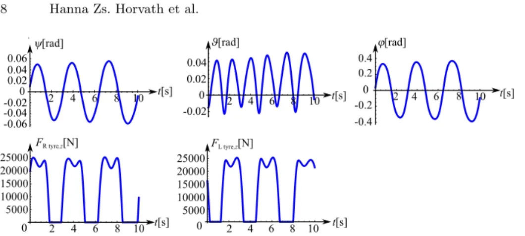
Numerical simulations were run in order to verify the critical parameter values given by the linear stability analysis and to check the nonlinear dynamics of the trailer. Fourth order Runge-Kutta method was used with fix time step. The sim- ulations were run for different initial conditions and for different spring stiffness values (3 DoF model) or for different towing velocity values (4 DoF model). Here we present only a simulation result forkl → ∞and for k = 75 000 N/m. As it can be seen, the motion tends to a large amplitude rocking motion, see Fig. 6.
Based on the numerical simulations, one can also draw the bifurcation diagram of the four degree-of-freedom system. The top left panel of Fig. 7 depicts the am- plitude of the roll angle with respect to the bifurcation parameterv. Subcritical Hopf bifurcation is suspected, which could be validated by using a bifurcation software. Panel (b) of Fig. 7 shows the effects of parametersf andeon the linear stability of the rectilinear motion. The red areas correspond to linearly unstable
2 4 6 8 10 2 4 6 8 10 0
0
Fig. 6.The time histories of the generalized coordinates and the vertical forces acting on the left or the right wheel in case ofk= 75 000 N/m.
rectilinear motion (snaking, rocking, roll-over of the trailer may appear), while the green areas correspond to linearly stable rectilinear motion.
a) b)
0 -0.1 -0.2 -0.3
10 20 30 40 50 v [m/s]
v [m/s]
0.02 0.04 0.06 0.08 0.10 0.12
stable
0 10 20 30 40 50
unstable [rad]
max
f =1 m e =1 m
0.4 0.8 1.2 1.4 1.0 0.6
0.2
10 20 30 40 50
0 v [m/s]
f [m]
f =1 m unstable
stable
10 20 30 40 50
0 v [m/s]
0.2 0.4 0.6 0.8 1.0 1.2 1.4
e [m]
e =1 m stable
unstable
Fig. 7. a) The bifurcation diagram of the four degree-of-freedom system, in case of k = 75 000 N/m (top panel) and the real part of the rightmost characteristic root of the linearised system (bottom panel). b) The effects of parametersfandeon the linear stability of the rectilinear motion. The green areas correspond to linearly stable, the red areas correspond to linearly unstable motion.
5 Conclusions
A mechanical model was introduced by which both the stability of two-wheeled suitcases and trailers can be investigated. It was shown that the linear stability of the rectilinear motion depends on the speed if the lateral displacement of the towing joint is considered. Critical stiffness values were also determined for the wheel suspensions. Simulation results also confirmed that the model can exhibit the large amplitude rocking motion and the nonlinear analysis of the model may lead to relevant information about the instability of the trailer.
Acknowledgements
This research has been supported by the UNKP-18-2-I-BME-173 New National Excellence Program of the Ministry of Human Capacities Hungary. This research was founded by the National Research, Development and Innovation Office under grant no. NKFI-128422. The publication of the work reported herein has been supported by ETDB at BME.
References
1. Troger, H. and Zeman, K.: A nonlinear-analysis of the generic types of loss of stabil- ity of the steady-state motion of a tractor-semitrailer. In:Vehicle System Dynamics 13(4), 161–172. p. 1984.
2. Darling, J., Tilley, D., Gao, B.: An experimental investigation of cartrailer high- speed stability, Proceedings of the Institution of Mechanical Engineers, Part D:
Journal of Automobile Engineering 223 (4)(2009)471484.
3. Suherman, S., Plaut, R.H., Watson, L.T., Thompson, S.: Effect of Human Response Time on Rocking Instability of a Two-wheeled Suitcase. In: Journal of Sound and Vibration, 207 (5). 1997. 617–625. p.
4. Plaut, R. H.: Rocking instability of a pulled suitcase with two wheels. In: Acta Mechanica 117, 165–179. p. 1996.
5. O’Reilly, O. M. and Varadi, P. C.: A travelers woes: some perspectives from dynam- ical systems, IUTAM Symposium on New Applications of Nonlinear and Chaotic Dynamics in Mechanics (Ed.:F. C. Moon), Kluwer Ac. Publ., Dordrecht, pp. 397–
406. p. 1999.
6. Facchini, G., Sekimoto, K., Courrech du Pont, S.: The rolling suitcase instability: a coupling between translation and rotation. In: Royal Society, 473(2202). 2017.
7. Horvath, H.Zs., Takacs, D.: Modelling and Simulation of Rocking Suitcases. In: Acta Polytechnica CTU Proceedings 18. 61-65. p. 2018. doi:10.14311/APP.2018.18.0061 8. Pacejka, H.B.: Tyre and Vehicle Dynamics, Elsevier Butterworth-Heinemann, Ox-
ford, 2002.