MODELLING AND SIMULATION OF ROCKING SUITCASES
Hanna Zs. Horvath
a,∗, Denes Takacs
a,ba Department of Applied Mechanics, Budapest University of Technology and Economics, Budapest, Hungary b MTA-BME Research Group on Dynamics of Machines and Vehicles, Budapest, Hungary
∗ corresponding author: horvath.hanna.zsofia@gmail.com
Abstract. The rocking motion of two-wheeled suitcases is investigated. A rigid body mechanical model of the suitcase is constructed. All of the possible motion states (both wheels on the ground, one wheel on the ground, none of the wheels on the ground) are taken into account. The switching between the motion states is accomplished by a simple impact model. The motion of the suitcase is investigated through numerical simulations, furthermore the domain of the attraction of the stable rectilinear motion is identified. The model is partly validated by experiments.
Keywords: stability, suitcase, non-smooth system, non-linear system.
1. Introduction
The rocking motion of two-wheeled suitcases is an annoying problem since it makes the use of suitcases uncomfortable in the everyday life. Large enough perturbations of the rolling suitcase can lead to the rocking motion, when the suitcase jumps from one of its wheels to the other, and in crucial cases the suitcase overturns. The topic is researched even nowadays (see [1]), although papers focusing on rocking suitcases were already published in the 90’s (see [2–4]).
The interest of researchers is supported by the fact that similar stability problem of trailers exists in vehi- cle dynamics (see, for example, [5]). From mechanical point of view, the analysis of the rocking suitcase problem is very complex. To begin with, the system is non-smooth since different equations describe the different motion states. Additionally, in case of con- tacting wheel, the spatial motion of the suitcase is influenced by the kinematic constraints, which makes the derivation of the equation of motion more compli- cated.
Due to this complexity, former studies on the field do not take into account all of the motion states of the suitcase, namely, the case when none of the wheels has contact with the ground is neglected. In this study, a mechanical model of the rocking suitcase is constructed in which all motion states are considered.
Experiments are also shown that confirm the presence of these motion states.
The contents of the paper is the following. The simplified mechanical model is introduced in Sec. 2.
The different motion states together with the corre- sponding number of the generalized coordinates are summarized in Sec. 3. The motion of the system is analysed through numerical simulations in Sec. 4.
Based on these simulations, experiments are carried out in Sec. 5. The comparison of the simulation and the measurement results can be found in Sec. 6.
2. Mechanical model
The simplified mechanical model is depicted in Fig.1.
The suitcase is pulled in theX direction with constant speedvby the ball-joint at A. The body of the suitcase is assumed to be rigid and it is modelled by means of massless rods and by a lumped mass mat the center of mass C of the suitcase. The position of the lumped mass is characterized with parameterseand f. The length and the width of the suitcase are described by the parameters land 2b, respectively, whilehis the distance between the towing point A and the ground.
The radius of the wheel (r) is assumed to be zero, which is a suitable approximation in our simplified model and it is also used in several studies (see, for example, [1]). On the one hand, the radius of the wheel is relatively small to the other dimensions of the suitcase and trajectory of the wheel center points and the paths of the contact points are very close to each other. On the other hand, the gyroscopic effect acting on the wheels is negligible since the mass moment of inertia of the wheels and the rotational speed are very small.
3. Motion states
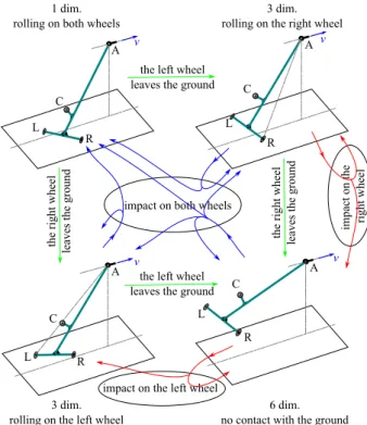
One can differentiate four different motion states of the suitcase: both wheels have contact with the ground, one wheel (right or left wheel) is on the ground, none of the wheels is on the ground. See Fig. 2, where the motion states are given together with the transitions between them. The different motion states correspond to 1, 3 and 6 dimensional state spaces, respectively.
When both wheels are on the ground, the suitcase makes in-plane motion and the equations of motion can be easily derived from the kinematic constraint of rolling. The position of the suitcase is given by the deflection angleψ (see in Fig.1), and the motion can be described in a one-dimensional phase space.
Having only one wheel on the ground is the most intricate case, since the motion is spatial, while the
Figure 1.The simplified mechanical model of a towed two-wheeled suitcase. The generalized coordinates for the right wheel rolling case.
Figure 2. The motion states with the correspond- ing dimensions of the state spaces, and the possible transitions between them.
kinematic constraint of rolling has to be considered.
Thus, for example, the equations of motion can be derived with the so-called Routh–Voss-equation. In this case, the governing equations lead to a three- dimensional phase space given by the tilting angleβ, the angular velocity Ω = ˙β and deflection angleψ(see Fig. 1).
If none of the wheels have contact with the ground, the motion is spatial but the system simplifies to a spatial mathematical pendulum with an extra rota-
tional degree of freedom about the axis determined by the points A and C. Namely, a six-dimensional state space governs the motion.
To make switches between the motion states, the detachments of the wheels from the ground and the impact between the wheels and the ground have to be handled. Namely, if the normal force at one of the wheels that has contact with the ground becomes zero, the wheel can leave the ground, and another motion state will govern the further motion of the suitcase.
Similarly, if one of the non-contacting wheel touches the ground with non-zero normal velocity, impact happens between the wheel and ground. To describe the impact, a complex impact model has to be applied since classical rigid body impact models could not be used to describe the practically observed transitions.
Here, we use a spring and a damper as a simple contact element to model the impact of the wheel. The deformations of the springs at the left and the right wheels can be described by the vertical positionszL andzRof the wheel centre points. If one of the wheels is on the ground then the contact spring is compressed and the vertical coordinate of the wheel is a small negative value. This small vertical displacement of the wheel centre point is negligible relative to the large scale motion of the suitcase. Moreover, since the dynamic of the impact is much faster than the position change of the body, the simulations of the impact can be carried out in another time scale. This method is often used for such multi-scale systems.
4. Numerical simulations
The governing equations and the impact model were implemented in computer code. The implemented equations of motion were rewritten into a system of first order ordinary differential equations. Fourth or- der Runge–Kutta method was used in these numerical simulations with fixed time step. Since the system is non-smooth and all motion states had different num- ber of degrees of freedom, and consequently different generalized coordinates and generalized velocities, the coupling between the motion states is a complex task.
See Fig. 2, where the transitions can be seen with all the possible scenarios.
Simulations were run for different initial conditions (β(t = 0) =β0, Ω(t = 0) = Ω0 andψ(t = 0) = ψ0
values) given for the left wheel rolling case and for various parameters (e.g. towing velocityv, geometrical parametersl, h, eandf). In our study, a motion is called stable if the simulation ends in the motion state in which both wheels are on the ground. Otherwise, the motion is called unstable, namely, the suitcase overturns.
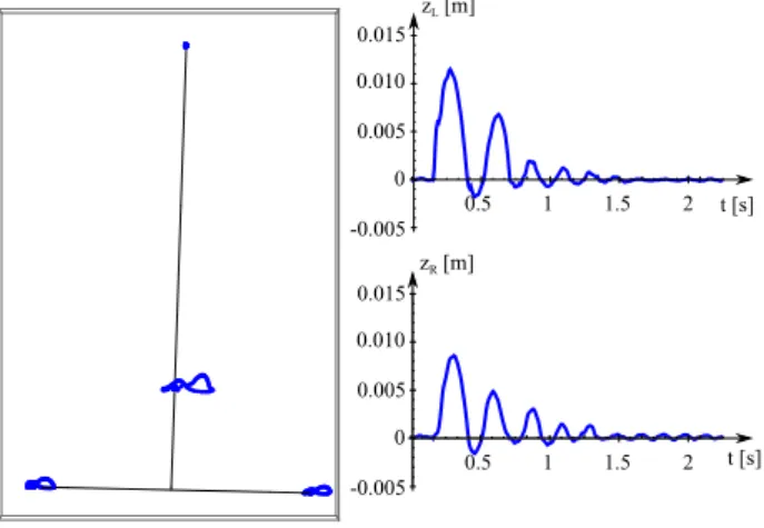
The time histories for a stable motion can be seen in Fig. 3. The suitcase rolls on its left wheel (panels in the first row), then the right wheel has an impact meanwhile the left wheel is already on the ground (panels in the second row show the deformationszL andzR of the left and right wheels, respectively), at
Figure 3. Time histories for the initial conditions:
β0=−0.2 [rad], Ω0= 0 [rad/s],ψ0= 0.1 [rad], and for parameter values: l= 0.58 m,h= 0.553 m,b= 0.16 m, e= 0.3 m,f= 0.1 m,m= 5 kg,v= 1 m/s.
last both wheels have contact with the ground (panel in the third row).
One can also draw the basis of attraction of the recti- linear motion by means of these numerical simulations.
In Fig. 4, the results of a simplified mechanical model are shown, where the fourth motion state (no wheels on the ground) was not considered. In the figure, one
Figure 4. The basis of attraction of the rectilin- ear motion. The parameter values are the following:
l = 1 m, h = 0.6 m, b = 0.3 m, m = 10 kg. Dif- ferent colours represent different basis of attraction considering differentf values.
can observe the attractive and the repelling regions, i.e. below and above a plotted line, respectively.
Other figures could be depicted considering different geometrical parameter (e,b,horl) values. If the value of b orl is increased, the attractive region grows as well. In case of increasing e, f or h, the repelling region grows. Due to the non-linearity of the system, there exists such towing velocities in case of a certain
f value, that for specific initial tilting anglesβ0 can lead to straight rolling, while a reduced initial angle (smaller perturbation) generates unstable behaviour and the suitcase rolls over, see the blue loop in Fig. 4.
Such phenomenon can be caused by the presence of unstable limit cycles, see [6]. Similar behaviour was also observed in our experiments.
5. Measurements
For the measurements, a model-based experimental setup was built and was placed on a treadmill while the towing point A was fixed with a ball-joint. The ve- locity of the treadmill can be varied between 0.5 km/h and 18 km/h. The measurement setup can be seen in Fig. 5.
Figure 5. The measurement setup. The parameter values: l= 0.58 m,b= 0.16 m,m= 5 kg. Parameters h,eandf and the velocityvcan be varied. Measure- ments showed that parameters eandf play a huge role in the stability of two-wheeled suitcases.
Two types of measurements were carried out in or- der to validate the results of the numerical simulations.
During the „classical” measurement, the towed struc- ture was perturbed, namely an obstacle was placed onto the treadmill at one of the wheels. The stability of the system could only be determined on statistical basis (out of ten measurements, how many where sta- ble and how many were unstable), since the identical perturbation could not be guaranteed during the mea- surement. Based on these measurements, we could conclude that parameterseandf play a huge role in the stability of two-wheeled suitcases. The domain of attraction of the rectilinear motion is large even in case of large velocities when the values of parameters eandf are small.
Measurements with OptiTrack motion capture sys- tem were also carried out. Four markers were placed on the suitcase (at the towing point A, at the cen- ter of mass C and at the left (L) and the right (R) wheels). An obstacle was placed before the left wheel.
Four cameras recorded the positions of the markers with respect to time and as a result, the spatial mo- tion of the suitcase was captured. Since this kind of measurement provides us information about the
markers’ positions, velocities and accelerations can be computed. As a result, important information can be gained about the level of perturbations with the evaluation of these measurements. Therefore, a more sophisticated identification of the basis of attraction can be carried out.
Snapshots about the measurements is shown in Fig. 6, where the rocking motion can be also observed.
The suitcase was perturbed by an obstacle before its left wheel, as a result, its left wheel leaves the ground (1). The suitcase rocks from its left wheel (2) to its right wheel (3). There are time instances when none of the wheels touches the ground (4). After this "flying"
motion, the body has an impact with the ground (5), then it overturns (6).
Figure 6. Snapshots about the measurement on the treadmill. The suitcase starts to rock and at the end, it overturns.
A stable motion is illustrated in Fig. 7, where the position of the markers are plotted for the measured time interval. It can be seen that the suitcase was perturbed at the left wheel, therefore it jumped from the ground and after falling back it had several impacts with the ground. The maximum of the left wheel’s vertical position was about 12 mm, while this value was 8 mm for the right wheel. As it was formally mentioned in Sec. 3, the negative values of the vertical positions of the wheels refer to the elastic deformations of the wheels. After some impacts, the rocking motion of the body dies away, the system stabilizes.
An unstable motion is depicted in Fig. 8. The suitcase rocks from one wheel to the other and the amplitudes grow with respect to time. As a result, the suitcase overturns.
6. Comparison
The validation of the model can be done by comparing the simulation results to the measurement ones. Here, we only give a comparison for a specific parameter setup of the suitcase, see Fig. 9. The parameter values of the experiment were: l = 0.58 m, b = 0.16 m, e= 0.135 m,f = 0.06 m,m= 7.2 kg, h= 0.553 m.
Figure 7. Example from an OptiTrack measurement, stable motion. The paths of the markers can be seen on the left figure. zLandzR denote the vertical dis- placement (with respect to time) of the left and the right wheel, respectively.
Figure 8. Example from an OptiTrack measurement, unstable motion. The paths of the markers can be seen on the left figure. zLandzR denote the vertical displacement (with respect to time) of the left and the right wheel, respectively.
In the figure, the result of the simulation is plotted with blue line, the attractive and the repelling regions with respect to the initial angleβ0can be seen below and above this line. The measurement results are plotted with red dots. The secondary axis at the right hand side of the diagram shows the diameterd0of the cylindrical obstacle, which were used to the initiate the rocking motion of the suitcase. In the figure, the diameter is considered to be proportional with the initial tilting angleβ0.
As it can be seen in the figure, the results of the simulations and the measurements are qualitatively the same. The attractive domain is smaller for larger speeds. Of course, some quantitative difference can be identified in the figure. One of the reason of this dif- ference is that we assumed here that the diameters of the obstacles are linearly proportional with the initial tilting angles. As mentioned before, this assumption is not perfect, and a more sophisticated comparison
Figure 9. Comparison of the results of the numerical simulation and measurements. The simulation result is depicted with the blue line, while the measurement points are the red dots.
of the simulation and measurement results could be done with the evaluation of OptiTrack measurements, which is the task of the future work.
7. Conclusions
A simplified mechanical model of two-wheeled rocking suitcases was constructed. A summary about the equa- tions of motion of the four different motion states were given, and also a simple impact model was presented.
Through numerical simulations important information about the non-linear behaviour of the suitcase was identified. An experimental rig was shown by which the numerical results were partly validated, namely, it was shown that the simulation results are qualitatively correct. Further research on the mechanical model and on the experiment can provide basic rules that can help the design of suitcases having better stability properties.
8. Acknowledgements
The publication of the work reported herein has been supported by ETDB at BME. The authors thank Laszlo Bencsik for his contribution in the use of the OptiTrack measurement system.
References
[1] Facchini, G., Sekimoto, K., Courrech du Pont, S.: The rolling suitcase instability: a coupling between
translation and rotation. In: Royal Society, 473(2202).
2017.
[2] Suherman, S., Plaut, R.H., Watson, L.T., Thompson, S.: Effect of Human Response Time on Rocking Instability of a Two-wheeled Suitcase. In: Journal of Sound and Vibration, 207 (5). 1997. 617–625. p.
[3] O’Reilly, O. M. and Varadi, P. C.: A travelers woes:
some perspectives from dynamical systems, IUTAM Symposium on New Applications of Nonlinear and Chaotic Dynamics in Mechanics (Ed.:F. C. Moon), Kluwer Ac. Publ., Dordrecht, pp. 397–406. 1999.
[4] Plaut, R. H.: Rocking instability of a pulled suitcase with two wheels, Acta Mechanica 117, 165–179. 1996.
[5] Troger, H. and Zeman, K.: A nonlinear-analysis of the generic types of loss of stability of the steady-state motion of a tractor-semitrailer, Vehicle System Dynamics 13(4), 161–172. 1984.
[6] Stepan, G.: Delay, nonlinear oscillations and shimmying wheels. In: Proceedings of Symposium CHAOS, Kluwer Ac. Publ., Dordrecht, pp. 373–386.
1997.