Damage Detection in a Fibre Reinforced Polymer Component by the Vibration Decay
Rate
Saad Alsarayefi, University of Miskolc, Faculty of Mechanical Engineering and Informatics.
University of Thi-Qar, College of Engineering.
Karoly Jalics, University of Miskolc, Faculty of Mechanical Engineering and Informatics.
Abstract--- Fibre reinforced polymer (FRP) components can have visible or non-visible damages because of an impact, crush, or fatigue during the regular operation hours. These components or structures have to be continuously monitored in order to ensure an early detection of deterioration. This paper uses the vibration decay rate experimentally as a method to detect damages in a FRP component. Measurement of reverberation time RT60 is executed in three different damage conditions of a specimen made of fibre reinforced polymer. The conditions of the specimen vary based on the damage existence in it. The major concern is on predicting damages presence by the measured data. The resulted data showed a clear difference among the three conditions proving the damages existence.
Keywords--- Fibre Reinforced Polymer, Composite Materials, Damage Detection, Decay Rate, Reverberation Time.
I. Introduction
Composite materials usages have been remarkably increased in almost all industry sectors. Fibre reinforced polymer (FRP) composites in particular, are significantly adopted in aerospace and automobile structures to satisfy the need for materials that are light in weight, costly effective, and good impact absorbents[1]. Fibre reinforced polymer (FRP) is a major class of composite materials that generally consists of a polymer as a matrix reinforced with a fibre. Usually, the fibre might be glass, carbon, and armed. However, other types of fibre sometimes are used such as wood, paper, or asbestos etc.[2].
Branched from the two main categories, thermoplastics and thermoset, polymer also could be of many types such as polyester, vinylester, polyurethane, and epoxy. Due to commercial needs, Glass or carbon is the most commonly used fibres as reinforcement to a matrix of thermosetting polymer such as epoxy and polyester to have FRP composite materials [3,4]. Moreover, thermoplastics matrices are still preferred to be used because of their property of reformed after the initial production. Regarding the application of FRP composites, their usage are remarkable in the aerospace and automobile industry field, ships and offshores platforms, sport goods, and chemical processing equipment. Also, FRP composite have exist in new markets of biomedical devices and civil structures.
New style of reinforcement forms such as carbon nanotube and nanoparticles with high performance resin systems have been used to produce new advanced forms of FRP composite rising their usage to an impressive range [5].
Generally, the most important properties of FRP composites that making them attractive to industries sectors are high specific strength, high specific stiffness, high fracture resistance, good abrasion, corrosion, impact, and fatigue resistance, and low cost [6].
On the other hand, damages may arise in the FRP components during operation putting the structure in a risk [7].
Due to the heterogynous microstructure of the materials and big difference of the constituent’s properties, the mechanism of the damage is not smoothly predicted and understood. Also, the interface presence and the fibre orientations give anisotropy in overall properties of the materials [7,8]. The diagnosed damages of composite materials are broadly classified under three main categories based on the structure of the material. These main categories are the micro-structure level, the macro-structure level, and the coupled micro-macro level mechanism failure. Under all three levels, the damages of composite materials could be [9]:
Fibre Fracture
Fibre Bending
Fibre Buckling
Matrix Cracking
Delamination
Fibre deboning
Others.
In order to have an early prediction of existence of visible or non-visible damages in composite structure and avoid failure, many structural health monitoring (SHM) methods have been revealed. Among these methods are guided waves method, acoustic emission methods, wave field imaging, modal analysis, frequency response function method, and others [9,10]. Thus, a lot of attention has been paid to the issue of damages detection in composite materials structures using acoustic emission and vibration-based methods [11–18].
Considering that the damages of composite materials has an effect on the vibration decay rate, this paper uses the experimental measured decay rate to predict the damage presence on the specimen. The measured decay rate shows an estimation of the dynamic behaviour of the target part[19]. The focus of the current investigation is to do laboratory work for measuring the vibration decay rate of a FRP composite component. The composite material specimen undergoes three different states based on the damage existence in it. In each state, the decay rate is done and the result data is measured. Distinguish the difference in the response of the dynamic behaviour in each case is analysed and considered to indicate the damage existence.
II. Vibration Decay Rate
Generally, there are several methods for the experimental determination of the damping of materials. One of these methods is the determination of the decay rate, which gives a relatively simple method for the loss factor determination [20].
The measurement of vibration decay rate is pretty like the measurement of the acoustic decay rate, which is well known in the room acoustics. The only difference is the usage of vibration sensor, e.g. accelerometer instead of microphones. The probe whose decay rate is determined, must be excited with a mechanical impulse (e.g. impact hammer) or with a burst random signal (electro-dynamic shaker) and the time signal of the accelerometer on the structure is measured (impulse response). After the stop of the excitation the gradual drop of the acceleration level within a certain time can be observed in the signal. The length of this time is depending on the internal damping of the material [21]. Additional effect, e.g. the noise radiation can act like a damping, but this phenomenon is neglected in this investigation.
The drop of the energy level by 106 (or by 60 dB) in the measured time is called the reverberation time RT60.The Reverberation Time (RT60) is the time that the sound pressure level takes to decrease by 60 dB after a sound source is abruptly switched off.
The RT60 decay rate must be filtered and the envelope should be created (e.g. by Schröder integration) in order to get the decay rates for every third octave frequency band. The Schröder integration is necessary to avoid the random error in the decay rate curves.
The filtered T60 is considered for the further calculation of the loss factor over the frequency by the following formula:
Where f is the mid frequency of a third octave band in Hz, RT60 is the decay rate for each third octave mid frequency in s. The value of 2, 2 can be derived from the energy drop to the one millionth of the initial value [21,22].
III. Experimental Work
3.1 The Test Specimen
For the investigations, a material type of MF GC 201 (melamine resin laminate) is selected. It is a glass reinforced polymer that consists of several layers of glass cloth impregnated with melamine. The specimen has a
simple rectangular shape with the dimensions of 500 x 200 x 3 mm (Figure 1). The material tensile strength is 150 Mpa while the comporessive strength is 275 Mpa. The modulus of elasticity of the material is1400 Mpa.
Figure 1: The Rectangular FRP Test Specimen 3.2 Creating Damages in the Specimen
In order to have the specimen cracked, an airgun type Diana 300R cal.177 was used. It has the maximum kinetic energy of E = 7.5 J at the muzzle. The gun “fires” lead pellets of the weight m = 0.53g of a calculated speed at the muzzle of 170 m/s. When firing from distance of 10 m, the contact place is barely visible. When firing from 1.5 m distance, the specimen was damaged with a crack of about 5 cm long. So the specimen was tested three times based on the conditions undamaged, damaged 1, and damaged 2.
Figure 2: The Test Specimen with Three Conditions 3.3 Test Equipment
B&K Pulse data acquisition
B&K 4397 accelerometer
Impact hammer (hand-made from a B&K 4397 accelerometer)
The software
Undamaged Damaged1 Damaged2
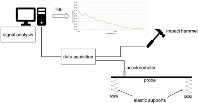
Figure 3: Schematic Representation of the Test Setup 3.4 Performing the Test
Three excitation points and one measurement point were determined to perform the hits and record the results.
The first excitation points is the middle of the specimen, while the second and third were (10, 10) and (3, 5) from the lower edge respectively. The measurement point is horizontally in the middle and vertically in the upper one-third of the part.
As mentioned, the test is done three times according to the three different conditions of the specimen. First time, the specimen is free of damages while the second time the specimen is damaged but the crack is barely seen by eye supposing that there are damages in the microstructure of the part which may be detected by the resulting signal.
The third test is done when the specimen is fully cracked as there is a gap in the spacemen.
During each time of the test, the excitation points are respectively hit ten times by the hammer and the recorded data were averaged. All recorded data are analysed by the Room Acoustic Wizard software and graphs are generated.
Test Results
Figure 4: RT 60 Decay Rate of the Original Specimen
Figure 5: RT 60 Decay Rate of Damaged-1 Specimen
Figure 6: RT 60 Decay Rate of Damaged-2
Figure 7: RT 60 Decay Rate of the Three Cases
0.00 0.05 0.10 0.15 0.20 0.25 0.30 0.35 0.40 0.45
100 1000
decay rate (T60), s
Frequency, Hz RT60 decay rate of FRP specimen
0.00 0.05 0.10 0.15 0.20 0.25 0.30 0.35 0.40 0.45
100 1000
decay rate (T60), s
Frequency, Hz RT60 decay rate of FRP specimen
0.00 0.05 0.10 0.15 0.20 0.25 0.30 0.35 0.40 0.45
100 1000
decay rate (T60), s
Frequency, Hz RT60 decay rate of FRP specimen
original_acc damaged_1_acc damaged_2_acc
The graphs (4-6) individually show the RT60 curve for the three cases of the specimen while graph 7 shows the RT60 of all three states together. As it is clear in figure 7, after 1000 Hz, there is a big difference can be seen among the three of them. The damaged condition no.2 (grey line) showing the highest RT60 conflicting the fact that there is no material (gab), so there is less damping. Same fact can be applied to the damaged case no.2 (blue line) considering that since there is a crack so there is damping less than original case resulting in higher RT60 than the original specimen. In accordance with the results above, the presence of damages can be estimated by the vibration decay rate in specific condition.
IV. Conclusion
As the composite materials usage has been significantly increased in major industry fields, the monitoring of damages presence in the composite parts and structure has to take a major importance. The damages in composite materials might exist non-visibly due to fatigue or crack. Thus, acoustic emission methods are used to predict damages existence in composite structure. Vibration decay rate is an acoustic method that has been used in this experimental investigation. The investigation used a composite material specimen that is made of glass fibre reinforced polymer. The specimen is put under three different damage conditions. The first is free of damages and the other two are different damage levels. The measured RT60 showed a clear difference after 1000 Hz of frequency between all three cases proving that this method is able to estimate the presence of damages in the part. In order to localize the damage, new investigation has to be done which is a future focus of the authors.
References
[1] D.K. Rajak, D.D. Pagar, P.L. Menezes, E. Linul, Fiber-reinforced polymer composites: Manufacturing, properties, and applications, Polymers (Basel). (2019). https://doi.org/10.3390/polym11101667.
[2] M. Alberto, Introduction of Fibre-Reinforced Polymers − Polymers and Composites: Concepts, Properties and Processes, in: Fiber Reinf. Polym. - Technol. Appl. Concr. Repair, 2013. https://doi.org/10.5772/
54629.
[3] D. Zindani, K. Kumar, An insight into additive manufacturing of fiber reinforced polymer composite, Int.
J. Light. Mater. Manuf. (2019). https://doi.org/10.1016/j.ijlmm.2019.08.004.
[4] G.D. Goh, Y.L. Yap, S. Agarwala, W.Y. Yeong, Recent Progress in Additive Manufacturing of Fiber Reinforced Polymer Composite, Adv. Mater. Technol. (2019). https://doi.org/10.1002/admt.201800271.
[5] T. Ozbakkaloglu, J.F. Chen, S.T. Smith, J.G. Dai, Applications of Fiber Reinforced Polymer Composites, Int. J. Polym. Sci. (2016). https://doi.org/10.1155/2016/5804145.
[6] S.E. Günaslan, A. Karaşin, M.E. Öncü, Properties of FRP materials for strengthening, Int. J. Innov. Sci.
Eng. Technol. (2014).
[7] T. Jollivet, C. Peyrac, F. Lefebvre, Damage of composite materials, in: Procedia Eng., 2013.
https://doi.org/10.1016/j.proeng.2013.12.128.
[8] N. Razali, M.T.H. Sultan, F. Mustapha, N. Yidris, M.R. Ishak, Impact Damage on Composite Structures – A Review, Int. J. Eng. Sci. (2014).
[9] A. Ghobadi, Common Type of Damages in Composites and their Inspections, World J. Mech. (2017).
https://doi.org/10.4236/wjm.2017.72003.
[10] R.B. Heslehurst, Defects and Damage in Composite Materials and Structures, 2014. https://doi.org/
10.1201/b16765.
[11] F.L.M. dos Santos, B. Peeters, H. Van der Auweraer, L.C.S. Góes, W. Desmet, Vibration-based damage detection for a composite helicopter main rotor blade, Case Stud. Mech. Syst. Signal Process. (2016).
https://doi.org/10.1016/j.csmssp.2016.01.001.
[12] A. Katunin, Modal-Based Non-Destructive Damage Assessment in Composite Structures Using Wavelet Analysis: A Review, Int. J. Compos. Mater. (2013). https://doi.org/10.5923/201310.01.
[13] A. Katunin, 1471. Damage assessment in composite structures using modal analysis and 2D undecimated fractional wavelet transform, J. Vibroengineering. (2014).
[14] M. Lakhdar, D. Mohammed, L. Boudjemâa, A. Rabiâ, M. Bachir, Damages detection in a composite structure by vibration analysis, in: Energy Procedia, 2013. https://doi.org/10.1016/j.egypro.2013.07.102.
[15] N.P. Yelve, M. Mitra, P.M. Mujumdar, Detection of delamination in composite laminates using Lamb wave based nonlinear method, Compos. Struct. (2017). https://doi.org/10.1016/j.compstruct.2016.09.073.
[16] M.A. Pérez, L. Gil, S. Oller, Impact damage identification in composite laminates using vibration testing, Compos. Struct. (2014). https://doi.org/10.1016/j.compstruct.2013.09.025.
[17] S.S. Kessler, S.M. Spearing, M.J. Atalla, C.E.S. Cesnik, C. Soutis, Damage detection in composite
materials using frequency response methods, Compos. Part BEngineering. (2002). https://doi.org/10.1016/
S1359-8368(01)00050-6.
[18] S.J. Alsarayefi, K. Jalics, The change of the NVH characteristics of composite vehicle components as a result of visible and not visible damages, in: Adv. Trends Eng. Sci. Technol. III- Proc. 3rd Int. Conf. Eng.
Sci. Technol. ESaT 2018, 2019. https://doi.org/10.1201/9780429021596-2.
[19] J. Chen, W. Liu, W. Liu, Experimental study on vibration decay rate characteristics and improvement for beijing metro, in: Environ. Vib. Transp. Geodyn., 2018. https://doi.org/10.1007/978-981-10-4508-0_19.
[20] G. Petrone, V. D’Alessandro, F. Franco, S. De Rosa, Damping evaluation on eco-friendly sandwich panels through reverberation time (RT 60) measurements, JVC/Journal Vib. Control. 21 (2015) 3328–3338.
https://doi.org/10.1177/1077546314522507.
[21] F. Fahy, Foundations of Engineering Acoustics, 2003. https://doi.org/10.1016/B978-0-12-247665-5.X5000- 0.
[22] Y.M. Chen, Q.X. Liu, J.K. Liu, Time-Dependent Decay Rate and Frequency for Free Vibration of Fractional Oscillator, J. Appl. Mech. Trans. ASME. (2019). https://doi.org/10.1115/1.4041824.